620
Chapter 15
Asynchronous Serial Interface C (UARTC)
User’s Manual U16580EE3V1UD00
(6)
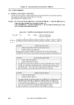
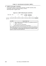
UARTCn status register (UCnSTR)
The UCnSTR register is an 8-bit register that displays the UARTCn transfer status and reception
error contents.
This register can be read or written in 8-bit or 1-bit units, but the UCnTSF bit is a read-only bit,
while the UCnPE, UCnFE, and UCnOVE bits can both be read and written. However, these bits
can only be cleared by writing 0 and they cannot be set by writing 1. (If 1 is written to them, the
hold status is entered.)
The initialization conditions are shown below.
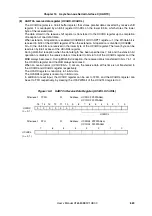
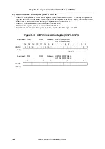
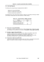
Figure 15-7:
UARTCn Status Register (UCnSTR) (1/2)
Register/Bit
Initialization Conditions
UCnSTR register
Reset input
UCnPWR bit of UCnCTL0 register = 0
UCnTSF bit
UCnTXE bit of UCnCTL0 register = 0
UCnPE, UCnFE, UCnOVE bits
0 write
UCnRXE bit of UCnCTL0 register = 0
After reset:
00H
R/W
Address:
UC0STR FFFFFA04H,
UC1STR FFFFFA24H
7
6
5
4
3
2
1
0
UCnSTR
UCnTSF
0
0
0
0
UCnPE
UCnFE
UCnOVE
(n = 0, 1)
UCnTSF
Transfer Status Flag
0
•
When UCnPWR bit of UCnCTL0 register = 0 or UCnTXE bit of UCnCTL0
register = 0 has been set.
•
When, following transfer completion, there was no next data transfer from
UCnTX
1
Write to UCnTXB bit
The UCnTSF bit is always 1 when performing continuous transmission. When initializing
the transmission unit, check that the UCnTSF bit = 0 before performing initialization. The
transmit data is not guaranteed when initialization is performed while UCnTSF bit = 1.
UCnPE
Parity Error Flag
0
•
When UCnPWR bit of UCnCTL0 register = 0 or UCnRXE bit of UCnCTL0
register = 0 has been set.
•
When 0 has been written
1
•
When parity of data and parity bit do not match during reception.
•
The operation of the UCnPE bit is controlled by the settings of the UCnPS1 and
UCnPS0 bits of the UCnCTL0 register.
•
The UCnPE bit can be read and written, but it can only be cleared by writing 0 to it,
and it cannot be set by writing 1 to it. When 1 is written to this bit, the hold status is
entered.
Содержание V850E/PH2
Страница 6: ...6 Preface User s Manual U16580EE3V1UD00...
Страница 16: ...16 User s Manual U16580EE3V1UD00...
Страница 28: ...28 User s Manual U16580EE3V1UD00...
Страница 32: ...32 User s Manual U16580EE3V1UD00...
Страница 84: ...84 Chapter 2 Pin Functions User s Manual U16580EE3V1UD00 MEMO...
Страница 144: ...144 Chapter 3 CPU Functions User s Manual U16580EE3V1UD00 MEMO...
Страница 192: ...192 Chapter 5 Memory Access Control Function PD70F3187 only User s Manual U16580EE3V1UD00 MEMO...
Страница 312: ...312 Chapter 9 16 Bit Timer Event Counter P User s Manual U16580EE3V1UD00 MEMO...
Страница 534: ...534 Chapter 11 16 bit Timer Event Counter T User s Manual U16580EE3V1UD00...
Страница 969: ...969 Chapter 20 Port Functions User s Manual U16580EE3V1UD00 MEMO...
Страница 970: ...970 Chapter 20 Port Functions User s Manual U16580EE3V1UD00...
Страница 976: ...976 Chapter 22 Internal RAM Parity Check Function User s Manual U16580EE3V1UD00 MEMO...
Страница 984: ...984 Chapter 23 On Chip Debug Function OCD User s Manual U16580EE3V1UD00 MEMO...
Страница 1006: ...1006 Chapter 24 Flash Memory User s Manual U16580EE3V1UD00 MEMO...
Страница 1036: ...1036 Chapter 27 Recommended Soldering Conditions User s Manual U16580EE3V1UD00 MEMO...
Страница 1046: ...1046 Appendix A Index User s Manual U16580EE3V1UD00 MEMO...
Страница 1052: ...1052 User s Manual U16580EE3V1UD00...
Страница 1053: ......

