Preface
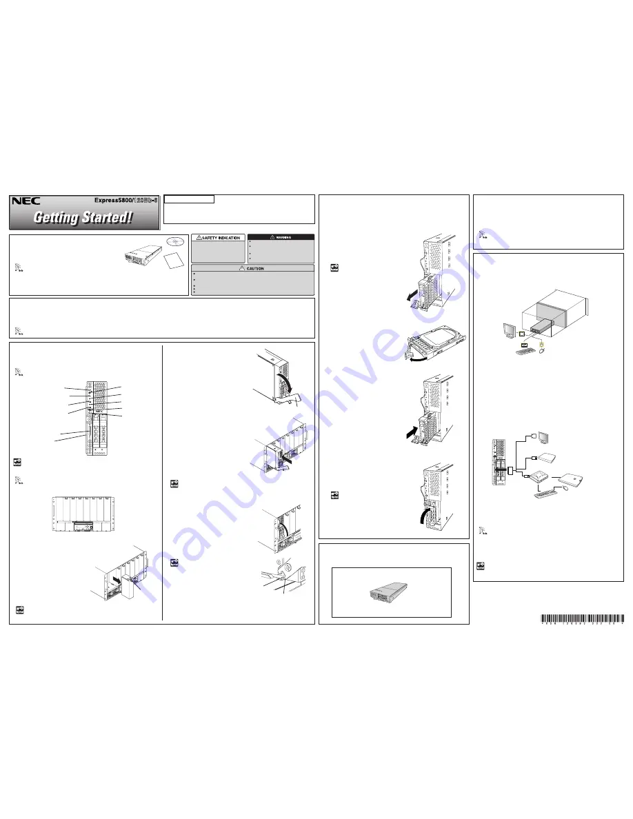
Unpack the carton box and make sure that you have everything
and that individual components are not damaged.
See the attached packing list.
The "NEC EXPRESSBUILDER" DVD is to be used when setting up (or resetting up) your server, therefore
store them in a designated place. We recommend you to print out the "User's Guide" stored in the
"NEC EXPRESSBUILDER" DVD and read it along with this guide before setting up your server. See the
"NEC EXPRESSBUILDER" on the rear face of this guide.
Blade Enclosure
The blade enclosure is the rack mount chassis exclusively used to be equipped with CPU blades and power supply unit. The blade enclosure is installed in the NEC rack
or NEC-recommended rack conforming to the EIA standard.
Refer to blade enclosure User's Guide for detail.
Refer to the following items of the User’s
Guide and follow the instructions for your
safety to setup the server:
"SYMBOLS USED IN THIS USER’S
GUIDE AND WARNING LABELS" and
"SAFETY INDICATION"
Do not disconnect/connect the power plug while your hands are wet.
Failure to follow this warning may cause an electric shock.
Make sure to power off the CPU blade and take out the CPU blade
from the blade enclosure before installing/removing internal optional
devices.
If it starts thundering, do not touch any part of the server including
the cables. Failure to follow this warning may cause an electric shock.
Never attempt to disassemble, repair, or alter the server on any
occasion other than described in this User's Guide.
At least four persons are required to carry the blade enclosure. Firmly hold the handle on the blade
enclosure while carrying the blade enclosure.
Do not install the server in dusty, humid, smoke or oily place. Also avoid installing the server in a place
exposed to direct sunlight.
Use the power cord that comes with your blade enclosure or NEC-specified power cord.
Plug in to a proper power source.
Do not install the enclosure where you need an extension cord.
CPU Blade
The CPU blade can be equipped with memory module and additional board.
Refer to Chapter 2 of the User's Guide stored in DVD-ROM.
Hard Disk Drive
Up to two hard disk drives can be connected to a CPU blade. Each drive must be
installed in a drive carrier. (To order a disk with a carrier, contact your sales
representative or dealer.)
856-126393-502-00 Rev.01, 4-2008
Read this Guide First.
Getting Started describes the procedures necessary for running the
server after you unpack the product. Follow these steps to complete
your installation successfully.
Go on to the next page.
1
DMP
RST
2
ID
0
1
POWER switch
DUMP switch
RESET switch
LAN1 Link/Access lamp (green)
LAN2 Link/Access lamp (green)
SUV connector
ID switch
ID lamp(blue)
STATUS lamp(green/amber/red)
POWER lamp (green/amber)
1
5
Cable Connection
The keyboard, mouse, display unit, and network devices are connected to the
Connector board in the blade enclosure that is connected with the MP connector
at the rear of the blade enclosure.
Refer to Chapter 2 of the User's Guide stored in DVD-ROM.
<Installation of CPU blades>
For options, refer to Chapter 9 of the User's Guide stored in the provided DVD-
ROM.
Installing Options
Install the optional devices required for the CPU blade and the blade enclosure.
Finally, connect the power cord coming with the power supply unit to the AC inlet
of power supply unit at the rear of the blade enclosure and the AC outlet for 200-
240 VAC.
The power cord coming with the power supply unit can be exclusively
used for the 200-240 VAC power. Connect the power cord only to an AC
outlet for 200-240 VAC.
Keep the removed slot cover for future use.
Do not remove the slot cover from any other slot.
Diskless model
Model
Prepare the hard disk drive and operating system separately.
Refer to blade enclosure User’s Guide for detail.
(2)
Gently put the CPU blade on the
clean, rigid, and flat desk. Loosen
the screw of the ejector to allow the
ejector to be opened.
(3)
Hold the frame of the CPU blade so
that its MP connector faces the
Blade Enclosure and the hard disk
drive downward.
(5)
Firmly push in the ejector of the CPU blade, and push the frame at the
front of the blade enclosure. Then, tighten the screw of the ejector to fix
the CPU blade to the blade enclosure.
Do not hold the ejector to install the CPU blade in the Blade Enclosure.
The ejector may be disengaged from the CPU blade that causes the CPU
blade to fall down. Or, the ejector may be bent that causes damage to
the CPU blade.
(1)
If an optional
slot cover is installed
on the slot on which the CPU blade
is to be installed, remove it. Unlock
the CPU blade by holding the lever
at the front, pull out the CPU blade,
and then remove the slot cover.
Make sure that the blade enclosure does not contain any CPU blade.
Install the blade enclosure in the rack. Then, install the CPU blade in the
blade enclosure.
1.
Remove a tray that does not contain
hard disk drive.
The SUV connector on the front of the CPU blade is not used in normal operation.
Use the SUV connector in the following cases:
ⓦ
Installing OS (when the CPU blade is installed in blade enclosure(10U))
ⓦ
Maintenance
ⓦ
Updating BIOS and firmware
Connect the K410-150(00) SUV cable (separately priced, or provided with the
Blade Enclosure) to the SUV connector. Then, connect peripheral devices to the
connectors of SUV cable.
* When you use the N8460-009 external DVD-ROM drive, use the branch
USB cable provided with the CPU blade.
2.
Release the lock of the lever on the hard
disk drive to make the lever opened.
Keep the removed hard disk
tray for future use.
3.
Hold the hard disk drive so that the BP
connector faces the CPU blade and the
lever on the front of the drive carrier
faces the top.
4.
Insert the end of the drive carrier into
the hard disk drive slot slowly and
carefully.
5.
Insert the drive carrier until it hits the
slot end, and lift the lever.
A click occurs to lock the drive carrier.
Make sure that the lever hook
is hung on the frame.
Eject lever
Lever
Make sure that the ejector hook is hit
to the frame of the blade enclosure, as
shown in the figure.
Ejector
Mouse
Keyboard
Monitor
1
DMP
RST
2
ID
0
1
CPU blade
External
DVD-ROM
drive*
Keyboard
Mouse
External
floppy disk drive
USB
USB
Self-powerd USB hub
Monitor
(4)
Align the frame of the CPU blade with
the guide rails of the blade enclosure,
and insert the CPU blade into the end
of blade enclosure slowly and
carefully.
Frame
Ejector hook


