background image

Release 6.0

77

User Guide

 Chapter 3 Installing the Disk Array System

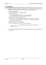
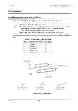
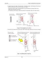
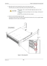
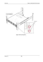
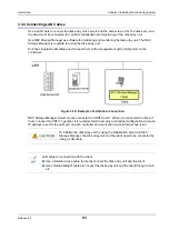
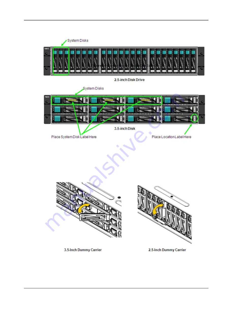
 Figure 3-11: Attaching Location Label

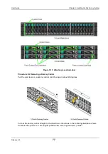
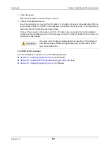
Procedure for Removing a Dummy Carrier

Pull the eject lever on a dummy carrier until the angle is about 40 degrees.

Pull out the dummy carrier straight to the direction as the arrows in the following illustration shows. 
Put back the eject lever to the original position after removing the dummy carrier.

Содержание M100

Страница 1: ...June 2012 Disk Array Unit User s Guide Release 6 0 NEC Storage NEC Storage M100 M300 Series 856 857386 101 A 856 857386 101 A ...

Страница 2: ...ange without notice This manual was created with the greatest care but in the event that any technical or editorial errors or omissions are found contact your dealer NEC shall not be liable for any claims of loss or lost profits caused by the use of this disk array unit regardless of mentioned above This unit is not intended to be installed in installations or equipment associated with human life ...

Страница 3: ... 1 3 1 Powering On the Disk Array System 54 1 3 2 Powering Off the Disk Array System 59 CHAPTER 2 Workflow Installation to Operation 62 CHAPTER 3 Installing the Disk Array System 65 3 1 Preparation 66 3 2 Installation 69 3 2 1 Mounting a Disk Array Unit on a Rack 69 3 2 2 Mounting a Disk Enclosure on a Rack 76 3 2 3 Installing Disk Drives 76 3 3 Connection 80 3 3 1 Overview 80 3 3 2 Connecting a D...

Страница 4: ...63 5 4 Checking Connection from Application Servers 167 CHAPTER 6 Initializing a Disk Array iSCSI 168 6 1 Overview 169 6 2 Initialization by NEC Storage Manager 170 6 2 1 Initialization Wizard 170 6 2 2 iSCSI Setup Tool 187 6 2 3 Binding a Pool 188 6 2 4 Binding a Hot Spare 193 6 2 5 Binding Logical Disk 197 6 2 6 Assigning Logical Disk 202 6 3 Checking Connection from Application Server 206 CHAPT...

Страница 5: ... 3 4 Errors in Hot Spare Binding 284 10 3 5 Errors in Logical Disk Binding 284 10 3 6 Errors in Retrieving Host Information 285 10 3 7 Assigning Logical Disk Errors 285 10 4 iSCSI Setup Tool Errors 286 10 4 1 iSCSI Setup Tool Windows Errors 286 10 4 2 iSCSI Setup Tool Linux Errors 288 10 4 3 iSCSI Setup Tool Error Codes 289 10 5 NEC Storage PathManager Windows Errors 292 10 6 NEC Storage PathManag...

Страница 6: ... 4 357 D 1 4 Setting up iSCSI Initiator 362 D 2 Setting up iSCSI Software Initiator 369 D 2 1 Overview 369 D 2 2 Logon Steps in Windows Environments 370 APPENDIX E How to Set Check Application Server Linux FC SAS 374 E 1 Installing NEC Storage Manager Agent Utility 374 E 1 1 Before Installation 374 E 1 2 Installation 375 E 2 Collecting Registering Host Information on Application Server 376 E 2 1 C...

Страница 7: ...ection Checksheet 431 J 1 Disk Array Unit 431 J 2 Disk Enclosure 432 APPENDIX K Notes Using iSCSI Supported Disk Array Unit 434 APPENDIX L iSCSI Connection Configuration Examples 436 L 1 Connection Between Application Server and LAN 436 L 2 Connection Between Management Server and LAN 437 APPENDIX M Script for Reporting Information Registered with iSNS Server 439 APPENDIX N Retrieve Initiator Info...

Страница 8: ...ure 3 4 Attaching Rail to Rear Pole 70 Figure 3 5 Screwing Rail on Front Pole 71 Figure 3 6 Attaching Rail to Rear Pole 71 Figure 3 7 Attaching Inner Rail 72 Figure 3 8 Attaching Ear Bezels or Front Bezel Clips 73 Figure 3 9 Securing Unit 1 74 Figure 3 10 Securing Unit 2 75 Figure 3 11 Attaching Location Label 77 Figure 3 12 Removing Dummy Carrier 78 Figure 3 13 Disk Drive 78 Figure 3 14 Inserting...

Страница 9: ...34 Figure 5 7 Set Time Setting NTP Server 136 Figure 5 8 Unlocking License 137 Figure 5 9 Host Port Connection Parameters FC 138 Figure 5 10 Edit Dialog 139 Figure 5 11 Port Mode Switching Screen 141 Figure 5 12 Finish Initialization Wizard 143 Figure 5 13 Pool Bind 144 Figure 5 14 Pool Bind Confirmation 146 Figure 5 15 Pool Bind Completion 148 Figure 5 16 Hot Spare Bind List Display 149 Figure 5 ...

Страница 10: ...lection Command 210 Figure 7 3 Starting Initialization Wizard 211 Figure 7 4 Welcome to Initialization Wizard 212 Figure 7 5 Setting Disk Array Subsystem Name 214 Figure 7 6 Set Time 215 Figure 7 7 Set Time Setting NTP Server 217 Figure 7 8 Unlocking License 218 Figure 7 9 Host Port Connection Parameters SAS 219 Figure 7 10 Edit Dialog 220 Figure 7 11 Finish Initialization Wizard 221 Figure 7 12 P...

Страница 11: ...7 Figure C 1 Unit with NF53x1 xFxx 10Gbps iSCSI 2port Controllers 321 Figure C 2 Unit with NF53x1 xFxx 1Gbps iSCSI 2port Controllers 321 Figure C 3 Configuration Example 322 Figure C 4 Microsoft iSCSI 1 Dialog Box 323 Figure C 5 Microsoft iSCSI 2 Screen 323 Figure C 6 Software Update Installation Wizard Screen 1 324 Figure C 7 Software Update Installation Wizard Screen 2 325 Figure C 8 Software Up...

Страница 12: ... Setup 365 Figure D 11 Advanced Settings Initiator IP Setup 366 Figure D 12 Discover Target Portal Dialog Box 367 Figure D 13 Authorization Failure Dialog Box 367 Figure D 14 Discovery Tab 368 Figure D 15 iSCSI Initiator Properties Targets Tab 370 Figure D 16 Connect To Target Dialog Box 371 Figure D 17 Advanced Setting General Tab 372 Figure E 1 Getting Started Host Information 377 Figure E 2 Set...

Страница 13: ... 25 Add Storage Wizard Screen 3 422 Figure I 1 Storage PathManager Environment Checker 424 Figure I 2 Storage PathManager InstallShield Wizard Welcome Page 1 425 Figure I 3 Storage PathManager InstallShield Wizard Welcome Page 2 426 Figure I 4 Storage PathManager InstallShield Wizard Ready to Install the Program 427 Figure I 5 Storage PathManager InstallShield Wizard Completed 428 Figure I 6 Stora...

Страница 14: ...d OS Combinations 91 Table 4 3 Initialization Status of Disk Array 110 Table 8 1 M100 Series Optional Parts 245 Table 8 2 M300 Series Optional Parts 247 Table 8 3 Optional Parts For All Series 248 Table 8 4 Disk Drive Features 249 Table 9 1 Relation between the initialization wizard and configuration settings 267 Table 9 2 Relation between the initialization wizard and configuration settings 269 T...

Страница 15: ...ises users that failure to take or avoid a specific action could result in physical harm to the user or the hardware Table 2 Terms Used Term Description Disk array unit Refers to a set configuration of DAC and DE Or if the DAC is used alone this denotes the DAC Disk Array Controller DAC This is a unit that controls the disk array functions This denotes a configuration consisting of a DAC enclosure...

Страница 16: ...em Chapter 3 Installing the Disk Array System This chapter explains how to install and connect this disk array system Chapter 4 NEC Storage Manager This chapter explains NEC Storage Manager used for managing this disk array system Chapter 5 Initializing a Disk Array FC This chapter explains the initialization of this disk array system in an FC environment Chapter 6 Initializing a Disk Array iSCSI ...

Страница 17: ... check an application server in the VMware environment when this disk array is configured for the FC connection Appendix H How to Set Check Application Server VMware iSCSI This appendix provides the steps you should follow while setting or checking an application server in the VMware environment when this disk array is configured for the iSCSI connection Appendix I Installing NEC Storage PathManag...

Страница 18: ... using NEC Storage Manager NEC Storage Software Configuration Setting Tool User s Manual GUI for the M Series This document provides information about how to set disk array configurations and how to view configuration information by using the Graphical User Interface GUI NEC Storage Software Messages Handbook This document lists messages error warning caution and information displayed by NEC Stora...

Страница 19: ...ersonnel This document is intended for use in a Windows or Linux environment For use in other OS environments NEC Storage disk array system must be set up by maintenance service provider Please contact your maintenance service provider This document provides a general setup method of NEC Storage disk array system Before you start the setup make sure to have products whose license sheets are shippe...

Страница 20: ...nance service provider to perform the setup described in this document Remarks This document provides information on functions achieved by the following program products NEC Storage Manager Express NEC Storage PathManager This document supports the following versions of the program products NEC Storage Manager Version 7 4 NEC Storage PathManager 5 0 for Windows NEC Storage PathManager 5 2 for Linu...

Страница 21: ...or any appropriate procedure for export from Japan Contact your sales agent or nearest NEC sales office if you need special material for the permission procedures In using this disk array system inconvenience may occur when a temporary power failure due to a cause such as lightning is experienced As a measure for temporary power failures it is recommended to use devices such as AC un interruptible...

Страница 22: ...e hazardous to their nearby areas The labels are intended for users to always be aware of any conceivable hazards when they use this disk array system Do not remove or damage the labels If any label is not attached coming off or unreadable contact your sales agent or maintenance personnel ...

Страница 23: ... 0 23 User Guide About Warning Labels Disk Array Controller The disk array unit might use two power supplies When disconnecting power be sure to disconnect both the power supplies to prevent an electrical shock ...

Страница 24: ...e This includes Disk Array Unit or electrical accessories such as cables or CDs When disposing of used products you should comply with applicable legislation or agreements you may have The mark on the electrical and electronic products only applies to the current European Union Member States Outside the European Union If you wish to dispose of used electrical and electronic products outside the Eu...

Страница 25: ...Release 6 0 25 User Guide About Warning Labels Power Supply AC Power Supply ...

Страница 26: ...Release 6 0 26 User Guide About Warning Labels Controller The following illustration shows the label for NF5311 SF11E The label is attached to the same location in other controllers ...

Страница 27: ...Release 6 0 27 User Guide About Warning Labels Battery ...

Страница 28: ...ase 6 0 28 User Guide About Warning Labels Disk Enclosure The disk enclosure might use two power supplies When disconnecting power be sure to disconnect the two power supplies to prevent an electrical shock ...

Страница 29: ...Release 6 0 29 User Guide About Warning Labels Power Cable AC Power Supply ...

Страница 30: ... batteries The batteries are installed as follows Controller lithium battery lithium cell Controller Ni MH nickel metal hydride battery For disposal of the disk array system including disposal or replacement of batteries refer to the following website http www nec co jp eco en business recycle ...

Страница 31: ...Release 6 0 31 Chapter 1 Overview This chapter provides an overview of the NEC Storage Disk Array Unit In this chapter Features on page 32 Components on page 33 Basic Operation on page 54 ...

Страница 32: ... disk drives and SSDs can be installed together on a disk enclosure The disk array can be connected as a storage system for Express5800 NX7000 NX7700i CX5000 and AIX servers 1 1 2 High Reliability and High Availability Key components such as controllers cache memories power supplies and fans are redundantly configured Cache data is dually written to controllers Even if a controller fails integrity...

Страница 33: ...ntroller This section describes names and functions of disk array components For more details about LED lighting patterns see Section 1 2 3 LED Display 1 2 1 1 Front View DAS072BU DAS073BU Figure 1 1 2 5 Inch Disk Drive Model DAS072AU DAS073AU Figure 1 2 3 5 Inch Disk Drive Model ...

Страница 34: ...formation on removing the front bezel see Section 8 3 1 Front Bezel Label Description 1 ID LED blue This LED is used to identify the unit 2 Service LED orange These LEDs indicate the status of the disk array controller 3 Power LED green 4 Standby LED white This LED indicates the DC off and on operation is available ...

Страница 35: ...ive Hard disk drive with a dedicated carrier HDD or SSD Dummy carrier Dummy to prevent wind blow 6 Key cylinder The key cylinder is used to lock the front bezel when it is attached to the unit 7 Active LED green Each disk drive has one each of these LEDs The LEDs indicate the disk drive status 8 Fault LED orange 9 Ejector The ejector is used to remove and attach the disk drive from or to a disk ar...

Страница 36: ...6 User Guide Chapter 1 Overview 1 2 1 2 Rear View With FC 2 Port and 1G iSCSI 2 Port controllers and AC power supplies With SAS 4 Port controllers and AC power supplies Figure 1 5 Rear View of Disk Array Controller ...

Страница 37: ...lease 6 0 37 User Guide Chapter 1 Overview Label Description 1 Power supply PS0 PS1 Two power supplies are installed on a disk array 2 Controller CONT0 CONT1 Two controllers are installed on a disk array ...

Страница 38: ... disk array 2 Power cable clamp The power cable clamp prevents the power cable from coming off unintentionally 3 Ejector The ejector is used to install and remove a power supply 4 AC switch The AC switch is used to power on and off input of power supply 5 Input Good LED green This LED is lit if power is supplied when the AC switch is turned on 6 Fault LED orange This LED is lit when an error is de...

Страница 39: ...tion LED blue This LED is not used in this disk array system The LED is not lit all the time 8 DC Good LED green This LED is lit when DC output is normal 9 Standby Power Good LED green This LED is lit when DC output is in the waiting status Label Description ...

Страница 40: ...Release 6 0 40 User Guide Chapter 1 Overview 1 2 1 4 Controller CONT ...

Страница 41: ...supplies PS0 PS1 or remove both power supply cords For information on AC operating mode see the description about AC operating mode in Section 1 3 1 Powering On the Disk Array System 2 Maintenance port The maintenance port is a 10M 100M 1Gbps LAN port used for connecting a maintenance PC This connector is not used under ordinary operation The port has a LINK ACT LED right and an SPEED LED left 3 M...

Страница 42: ...y according to the controller type 6 Disk port The disk port is used to connect to the next disk enclosure A controller has one disk port The port has a fault LED below the port and a link LED above the port 7 USB port These USB 2 0 ports are used for debugging They are not used under normal operation 8 Ejector The ejector is used to install and remove the controller Label Description ...

Страница 43: ...ler For details see Section 1 2 1 1 Front View 1 2 2 2 Rear View DEU191AU DEU191BU Figure 1 8 Disk Enclosure Rear View with AC Power Supplies 1 2 2 3 Power Supply Power supplies of a disk enclosure are the same as the power supplies of the disk array controller For details see Section 1 2 1 3 Power Supply Label Description 1 Power supply PS0 PS1 Two power supplies are installed on a disk enclosure...

Страница 44: ...tus display LED For details about the status display LED see Section 1 2 3 LED Display 6 Disk port IN A disk port IN is used to connect the disk array controller or disk enclosure located before the given enclosure Each adapter has two disk ports for IN Typically only the right IN port is used Each port has a fault LED right and a link LED left 7 Disk port OUT The disk port OUT is used to connect ...

Страница 45: ...losure and Disk Drives Table 1 1 ID LED blue 1 ID LED Status Not lit Not selected Lit Selected Table 1 2 Service LED Power LED orange green 2 Service LED 3 Power LED Meaning Not lit Lit Running successfully Lit Lit Maintenance being required or being performed such as in the course of recovery Lit 0 2 seconds Not lit 0 2 seconds Lit In the course of power on Lit 4 seconds Not lit 8 seconds Lit Mai...

Страница 46: ... When access from the host connection port is restored ordinary status is restored Table 1 3 Standby LED white 4 Standby LED Status Not lit DC on and off operation is not available Lit DC on and off operation is available Table 1 4 Active Fault LED green orange of Disk Drive 5 Active LED 6 Fault LED Status Not lit Not lit Powered off Lit Not lit Ordinary READY Flashing Not lit Ordinary in the cour...

Страница 47: ...nput good LED 2 Fault LED 3 Service action LED 4 DC good LED 5 Standby good LED Status Green Orange Blue Green Green Lit Not lit Lit Running successfully Lit Lit Lit Problem in power supply fan Power supply temperature warning Lit Lit Not lit Power supply output problem Power supply temperature problem Lit Lit INPUT ON 12V and 5V no output 5Vstb output Not lit Input problem The service action LED ...

Страница 48: ...Release 6 0 48 User Guide Chapter 1 Overview 1 2 3 3 Controller CONT ...

Страница 49: ... port LINK ACT LED green 4 Maintenance port LINK ACT LED green The LED is lit when it is connected The LED flashes when data is transferred 1 Management port SPEED LED green orange 3 Maintenance port SPEED LED green orange When operating at 100 Mbps The LED lits in green When operating at 1 Gbps The LED lits in orange Table 1 7 Status Display LED 5 Ready LED 6 Fault LED 7 ID LED 8 BBU LED Status G...

Страница 50: ...cked Lit 1 second Not lit 1 second Flashing fast Updating firmware online Lit The device is selected Lit Detected BBU failure Flashing Warning for the end of the BBU life cycle Table 1 7 Status Display LED 5 Ready LED 6 Fault LED 7 ID LED 8 BBU LED Status Green Orange Blue Orange Table 1 8 Host Port Status Host port Status 9 Link LED L green Lit linkup Not lit link down 10 Active LED A green Lit o...

Страница 51: ...Chapter 1 Overview Location and port number Location and port number Table 1 9 Disk Port Status Disk port Status 11 Link LED LNK Green Lit linkup Not lit link down 12 Fault LED FLT Orange Lit An error is detected Not lit Normal ...

Страница 52: ...ully Flashing Flashing in a cycle of 0 5 second Initializing firmware Flashing Flashing in a cycle of 1 second Error between adapters has been detected Flashing Lit Error in the adapter has been detected Operation continued Not lit Lit Error in the adapter has been detected Unable to continue operation Lit The device is selected Table 1 11 Disk Port Status Disk port Status 4 Link LED LNK Green Lit...

Страница 53: ...Release 6 0 53 User Guide Chapter 1 Overview Location and port number DP1 IN is not used under normal operation ...

Страница 54: ...a certain command to the disk array unit When AC operating mode is disabled you need to use the power switch to control the power of the disk array unit For information on how to change the factory default settings to disable AC operating mode see NEC Storage Software Configuration Setting Tool User s Manual GUI for the M Series When AC operating mode is disabled the power control function through...

Страница 55: ...y one second until fans start to rotate The disk array controller will be powered on The disk enclosures will be powered on sequentially as the disk array controller is powered on Proceed to step 3 When AC operating mode is enabled factory default settings the disk array system with AC power supplies is automatically powered on at the time the disk array controller is powered on while the disk arr...

Страница 56: ...e disk array system until the Power LED green located at the front of the disk array unit is lit and the Service LED orange goes off after cyclic flashing 4 Power on the application servers hosts Step Operation It takes approximately six for minimum configuration to eight maximum configuration minutes for initialization and the self test after the power on During this period the Service LED orange...

Страница 57: ...s Linux This control system uses a server for power control which can be associated with hosts For details see ESMPRO AC manual ESMPRO AC Automatic operation Windows Linux This control system uses a server for power control and allows for automatic operation For details see ESMPRO AC manual UPS Does not work with UPS Not specified This control system is for instantaneous power interruption Because...

Страница 58: ... array system power must be turned off in a certain order AC power off sequence 1 Application server 2 FC switch 3 Disk array unit 4 Disk enclosure 5 Management server Only ESMPRO AC If multiple disk enclosures are used you do not need to specify the sequence of power off among the disk enclosures Figure 1 14 AC Power Off Sequence FC Port Connection ...

Страница 59: ...wer supplies The power supply of the disk array system can now be stopped Make sure to check application servers hosts are stopped or powered off Press the DC button of either of the controllers CONT You do not need to press buttons of both controllers With this process the disk array unit writes data that is on caches and has not been written to disks to disks When writing the data is complete th...

Страница 60: ...n reserved volume has been created the update information mentioned above is created only on the cache memory In these circumstances even if the disk array system is powered off according to the procedure described in Section 1 3 2 Powering Off the Disk Array System the status of the disk array system becomes backup status when the disk array system is stopped If the backup fails the storage syste...

Страница 61: ...to disk drives and prevents data loss even if a situation mentioned above arises Completion of Auto Cache Flush can be checked from high speed flashing of POWER LED that flashes every 0 2 seconds Copy is started again All the spaces of logical disks are targeted which means full copy is performed When the replication function is used it is strongly recommended that a user use the storage system in...

Страница 62: ...d installation CDs Perform the preliminary setup of the application server See Section 3 1 Preparation 2 Hardware Installation Install disk array unit in the rack Optional Install disk enclosure in the rack Install disk drive See Section 3 2 Installation 3 Cable Connections Connect the following cables Optional SAS cable to connect disk array unit and disk enclosure FC cable to connect disk array ...

Страница 63: ...n NEC Storage Manager client machine Configure the IP address of the disk array using Network Setting Tool Set the time zone of the disk array See Section 4 3 Setup 3 NEC Storage Manager Agent Utility Install the NEC Storage Manager Agent Utility on an application server See Section 4 4 Installing NEC Storage Manager Agent Utility on Application Server 4 NEC Storage Manager Client Enter the name o...

Страница 64: ...nager a Start the Initialization Wizard and follow the instructions b Bind Pool c Optional Bind Hot Spare d Bind Logical Disk e Set the application server host to which logical disk will be assigned f Assign logical disk to the application server See Section 5 3 Initialization by NEC Storage Manager 3 Check if the application server to which the logical disk has been assigned is connected to the d...

Страница 65: ...6 0 65 Chapter 3 Installing the Disk Array System This chapter describes how to prepare install and connect a disk array unit In this chapter Preparation on page 66 Installation on page 69 Connection on page 80 ...

Страница 66: ...it and a client directly Use straight cables to connect a unit and a client via hub etc Interface cables to connect application servers IP addresses to be assigned to the disk array unit as many as ports to be connected Also contact the network administrator to obtain subnet masks and gateway addresses Network devices as necessary Phillips screwdriver No 1 for screwing Three or more disk drives Pu...

Страница 67: ...e host bus adapters location at the server extension slot and the WWPN if the host bus adapter fails In case the WWPNs of the host bus adapters cannot be retrieved by using software you may need to enter the WWPNs manually b Attach the host bus adapters Skip this step when host bus adapters have already been attached to the application servers Attach the host bus adapters to the application server...

Страница 68: ... Skip this step when NEC Storage PathManager has already been installed and set up on the application servers or no Storage PathManager will be installed For information about how to install Storage PathManager see Appendix H How to Set Check Application Server VMware iSCSI Complete step c before implementing step d ...

Страница 69: ...ay system to a rack Figure 3 2 Rack Mount Kit Follow the descriptions in Installation Guide A disk array unit weighs up to 31Kg when 3 5 inch hard disk drives are installed A disk enclosure weighs up to 29Kg when 3 5 inch disk drives are installed They must be mounted on a rack by two or more persons Mount disk enclosure s and then a disk array unit from the top of a rack Table 3 1 Components of R...

Страница 70: ... when it is seen from the front side Attach the rail to the left side of the rack which is seen from its front side Figure 3 3 Rail 2 Align both sides of the bottom of the rail with the 1U delimiting marks on the rear pole of the rack and then let the two projections on the inner into the holes on the pole Figure 3 4 Attaching Rail to Rear Pole ...

Страница 71: ...s on the pole There are two types of rack rectangular hole rack and circular hole rack Each of them has a different type of projection on the rail Insert M5 screws into the two central screw holes on the front pole of the rack to screw the rail Figure 3 5 Screwing Rail on Front Pole 4 Move the inner towards the rear pole of the rack and let the two projections in the holes on the pole Figure 3 6 A...

Страница 72: ...hing Inner Rail 6 Attach the rail R on the right side of the rack by using the same procedure as above Installation of rack mount kit is now complete 7 Before mounting a unit attach ear bezels or front bezel clips If you use an optional front bezel attach the bezel clips that come with the front bezel as shown in the following illustration If no front bezel is used attach the ear bezels that come ...

Страница 73: ...Release 6 0 73 User Guide Chapter 3 Installing the Disk Array System Figure 3 8 Attaching Ear Bezels or Front Bezel Clips ...

Страница 74: ...e rail 9 Secure the unit on the front side of the rack Screw two points on each of the right and left sides of the front side of the unit by using M5 screws Mounting the unit on the rack is now complete Mounting a unit on a rack should be implemented by two or more persons Take care not to injure your fingers etc when moving a unit because it is heavy Take care not to drop a unit when moving it Fi...

Страница 75: ...Release 6 0 75 User Guide Chapter 3 Installing the Disk Array System Figure 3 10 Securing Unit 2 ...

Страница 76: ...disk drive Use a new disk drive you have purchased as a product The operation of a diverted or a reused disk drive is not guaranteed Do not use a disk drive that has been diverted from or used in other system For more information on how to attach detach a front bezel see Section 8 3 1 Front Bezel Disk drives are electrical parts When handling them take an anti static measure such as using a wrist ...

Страница 77: ...bel Procedure for Removing a Dummy Carrier Pull the eject lever on a dummy carrier until the angle is about 40 degrees Pull out the dummy carrier straight to the direction as the arrows in the following illustration shows Put back the eject lever to the original position after removing the dummy carrier ...

Страница 78: ...rive 3 5 inch and 2 5 inch Each of them has three types SAS drive NL SAS drive and SSD The front label on a disk drive shown by red circles on the figures below indicates the type of the drive Figure 3 13 Disk Drive Figure 3 12 Removing Dummy Carrier Do not dispose of the dummy carriers you removed ...

Страница 79: ...he eject lever is closed by default on the disk drive 2 Hold the disk drive steadily and insert it to the middle of the slot in the disk drive unit or a disk enclosure Figure 3 14 Inserting Disk Drive 3 With the eject lever on the disk drive open slowly insert the disk drive until it stops while holding the eject lever 4 Press the eject lever into the disk drive to lock the drive ...

Страница 80: ... For 10Gbps iSCSI To connect an NIC or switch on an application server to the disk array unit be sure to use an optical Ethernet cable conforming to 10GBASE SR To connect the disk array to power supply use the power supply cables that come with the disk array unit 2 Maximum cable length a FC cable b iSCSI cable Table 3 2 FC Cable Length Host Interface Max Cable Length Remarks 2 Gbps 300 m Optical ...

Страница 81: ...ion that works together with NEC Storage PathManager To implement this recommended connection two host bus adapters need to be installed on the application server Two FC cables are also required for connecting the disk array unit and the host bus adapters Figure 3 15 Connection Example Following is the procedure for connecting the disk array unit and the application server by using FC cables To pr...

Страница 82: ...ter on the other end of the FC cable to the connecter of a host bus adapter installed on the application server In the same way connect the other controller to the connector on another host bus adapter For iSCSI Port Connection See the Preparation section in one of the following sections Section C 1 Initializing Application Server on Windows Section E 1 Installing NEC Storage Manager Agent Utility...

Страница 83: ...the controllers Figure 3 16 Example of LAN Cable Connection NEC Storage Manager Server can be connected to CONT0 and 1 When it is connected to either of them connect it to CNT0 in general It is recommended to employ a redundant configuration where an IP address is set for the LAN port on each controller and connection via an Ethernet hub is set To initialize the disk array unit by using the initia...

Страница 84: ...y is turned on When power is not fed connect the power supply cables and then start feeding power Avoid overloading on an electrical circuit to prevent fire Do not plug in a power supply cable to an outlet and panel board with a wet hand Doing so may cause an electric shock Do not place a heavy item on a power supply cable Doing so may damage the shield of the cable which may cause a fire or an el...

Страница 85: ...able in the clamp and lightly lock the clamp part 2 Move the clamp part in the direction shown by the arrow below close to the lowest part of the plug and then fix the clamp part steadily Figure 3 17 AC Cable A loosely locked clamp part may cause the power supply cable to come off Fix the power supply cable clamp steadily at a location close to the lowest part of the power supply cable ...

Страница 86: ...y on application servers how NEC Storage Manager is provided and how to start NEC Storage Client In this chapter How NEC Storage Manager is provided on page 87 Before Starting NEC Storage Manager Client on page 93 Setup on page 99 Installing NEC Storage Manager Agent Utility on Application Server on page 121 Starting NEC Storage Manager Client on page 122 ...

Страница 87: ...on and management of multiple disk arrays including the old D S series by a single management server NEC Storage Manager Suite also allows for integrated management of the entire system by working together with middleware products such as WebSAM ESMPRO or SSC This document describes initialization and settings of a disk array using NEC Storage Manager Express The descriptions in the rest of this c...

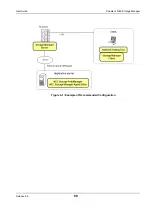
Страница 88: ...Release 6 0 88 User Guide Chapter 4 NEC Storage Manager Figure 4 1 Example of Recommended Configuration ...

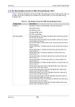
Страница 89: ... Windows 7 Ultimate without any Service Pack and Service Pack 1 Microsoft Windows 7 Ultimate x64 without any Service Pack and Service Pack 1 Microsoft Windows 7 Enterprise without any Service Pack and Service Pack 1 Microsoft Windows 7 Enterprise x64 without any Service Pack and Service Pack 1 Microsoft Windows 7 Professional without any Service Pack and Service Pack 1 Microsoft Windows 7 Professi...

Страница 90: ...cts without Hyper V are also supported The Server Core installation option is not supported Web browser Windows Microsoft Internet Explorer Version 6 to 9 32 bit version For Windows Vista or Windows Server 2008 only Version 7 or later are supported For Windows 7 and Windows Server 2008 R2 only Version 8 or later are supported Linux Firefox 3 0 3 5 and 3 6 Java Runtime Environment JRE One of the fo...

Страница 91: ...Supported Windows 7 Ultimate x64 Supported Windows 7 Enterprise x64 Supported Windows 7 Professional x64 Supported Windows Server 2003 Standard Edition Supported Windows Server 2003 R2 Standard Edition Supported Windows Server 2003 Standard x64 Edition Supported Windows Server 2003 R2 Standard x64 Edition Supported Windows Server 2003 Enterprise Edition Supported Windows Server 2003 R2 Enterprise ...

Страница 92: ...C Storage Manager Client WebGUI as well as the product Use the JRE contained in the NEC Storage Manager Express Setup and Utility CD ROM or NEC Storage Manager CD ROM for first installation However it is recommended to use the latest version among the supported JRE versions after the installation because the supported versions may include a version for which security vulnerability issue is reporte...

Страница 93: ...w Once the configuration is complete you do no need to configure the Web browser in subsequent startups of NEC Storage Manager Client 1 Follow the steps below to configure the disk array to be connected as Trusted Sites The following screenshot is for Internet Explorer 8 on Windows 7 a From Control Panel select Internet Options and click the Security tab b Select the Trusted sites icon and click S...

Страница 94: ... connected for example http the IP address host name of the disk array to be connected in the Add this website to the zone box and click Add The Require server verification https for all sites in this zone check box should be cleared Figure 4 3 Trusted Sites Window d Click OK to close the window ...

Страница 95: ...ge Manager 2 Follow the steps below to configure the security level of Trusted sites a From Control Panel select Internet Options and click the Security tab b Select the Trusted sites icon and click Custom level Figure 4 4 Internet Options Window ...

Страница 96: ...close the window When your environment is Windows configure Java as well before you start using NEC Storage Manager Client Web GUI Once the configuration is complete you do not need to configure Java again in subsequent startups of NEC Storage Manager Client When you are using Internet Explorer Version 7 or later do not enable Protected Mode of the Trusted sites ...

Страница 97: ...er 2008 or later environment right click the icon to start the Web browser to select Run as administrator C Program Files Java jre6 bin javacpl exe default installation in the 32 bit version OS C Program Files x86 Java jre6 bin javacpl exe default installation in the 64 bit version 2 Click the Update tab and clear the Check for Updates Automatically check box Figure 4 6 Update Tab of Java Control ...

Страница 98: ...nvironment right click the icon to start the Web browser to select Run as administrator C Program Files Java jre6 bin javacpl exe default installation in the 32 bit version OS C Program Files x86 Java jre6 bin javacpl exe default installation in the 64 bit version 2 Click the Advanced tab and clear the Enable the next generation Java Plug in requires browser restart check box Figure 4 7 Advanced T...

Страница 99: ...ted automatically when the NEC Storage Manager Express Setup and Utility CD ROM is set For the M300 series disk arrays it is necessary to prepare NEC Storage BaseProduct Follow the instruction on the screen to complete the installation Follow the steps below to use Storage Manager Setup 1 Log in as Administrator 2 Set the CD ROM in the CD ROM drive of the client 3 Storage Manager Setup automatical...

Страница 100: ...Release 6 0 100 User Guide Chapter 4 NEC Storage Manager 4 Select Setup for M series and click Next Figure 4 8 Start Page of Setup ...

Страница 101: ...Release 6 0 101 User Guide Chapter 4 NEC Storage Manager 5 Select Setup as a disk array in Quick Install and then click Next Figure 4 9 Select Installation Method ...

Страница 102: ...Release 6 0 102 User Guide Chapter 4 NEC Storage Manager 6 Check the software to be installed and then click Next Figure 4 10 Confirm Software ...

Страница 103: ...anager 7 Make sure to read all of the software license agreement If you accept the agreement select I accept terms of the license agreement and then click Next If you do not accept the agreement you cannot use the software Figure 4 11 License Agreement ...

Страница 104: ...ck Next If you want to install the software in a folder other than the shown destination click Browse to select the folder you want to use Figure 4 12 Choose Destination Location 9 Install the software as you are prompted by the instructions If you install JRE in this step perform the JRE preparation described in Section 4 2 Before Starting NEC Storage Manager Client ...

Страница 105: ...n The IP addresses consist of the IP addresses of controllers BMC addresses of controllers and a floating address If NEC Storage Manager Client is used an IP address should be set to each of controllers A BMC address is a communication port to be used to link NEC Storage Manager with ESMPRO AutomaticRunningController ESMPRO AC When the installation is started from by selecting Setup for M series i...

Страница 106: ...er to a directory you want to use for example tmp cp r cdrom JRE LINUX jre 6u21 linux i586 rpm bin tmp Run the installer you have copied tmp jre 6u21 linux i586 rpm bin 5 Use the rpm command for the installation rpm ivh cdrom NETCONFIG LINUX iSMnetconfig rpm 6 The following message is shown when the installation is complete 7 Unmount the CD ROM Use the unmount command umount cdrom 8 Register JRE w...

Страница 107: ...ge Manager Client machine over a LAN to execute Network Setting Tool Note the following when you connect a disk array for which the network settings have not been configured The IP addresses BMC addresses and a floating address of the disk array are 0 0 0 0 by default Connect the disk array to physically the same network where the NEC Storage Manager Client machine belongs i e the network not beyo...

Страница 108: ...e same segment as the machine on which Network Setting Tool has been installed by referring to the example shown below For example The address of the machine on which Network Setting Tool is installed is 192 168 0 20 24 Figure 4 14 Connect Disk Array Example 1 IP addresses have the same segment as the machine on which Network Setting Tool has been installed 2 When the disk array and the NEC Storag...

Страница 109: ...s automatically started after Network Setting Tool is installed by using Storage Manager Setup To configure manually click Start All Programs Storage Manager Network Initialization Tool Network Setting Tool to run Network Setting Tool In a Linux environment 1 Run the iSMinitool command Figure 4 15 Select a Disk Array Start up ...

Страница 110: ...as been installed and IP addresses have been configured finished is shown in the Status column For details about information shown for the Status column see Table 4 3 Table 4 3 Initialization Status of Disk Array Status Description Displayed information Disk array status not set Disk array has just been installed The disk array is not monitored by NEC Storage Manager because the network settings h...

Страница 111: ... the disk array by NEC Storage Manager Figure 4 17 Network Settings 5 Configure a floating address for the disk array and the network address BMC address and floating address for each of disk array controllers When the settings are configured for a controller not connected by a LAN cable monitoring is disabled ...

Страница 112: ... 0 0 0 Floating address is an IP address that can be set to a disk array in addition to the network addresses configured for each controller Setting a floating address allows you to access a disk array while controllers remain transparent It is recommended to configure a floating address for ease of management When a floating address is specified the following conditions must be satisfied for netw...

Страница 113: ...ick Cancel to change the settings If any IP address subnet mask or gateway address is not configured correctly configuring the network settings fails As a result monitoring by using NEC Storage Manager is not enabled If the error message The setting of IP address failed is shown refer to the help of Network Setting Tool ...

Страница 114: ...ou set the NEC Storage Manager Express Setup and Utility CD ROM and it allows you to perform the settings as prompted Depending on your environment it may not start automatically in which case run the following program in the CD ROM INSTALL WINDOWS ISMSETUP EXE Follow the steps below by using NEC Storage Manager Setup 1 After you configure IP addresses as described in Section 4 3 2 Configuring IP ...

Страница 115: ...Release 6 0 115 User Guide Chapter 4 NEC Storage Manager 2 Select Setup for M series and click Next The Select Installation Method page appears Figure 4 20 Select Installation Method ...

Страница 116: ...6 User Guide Chapter 4 NEC Storage Manager Figure 4 21 Setting in a Time Zone 3 To set a time zone select Yes and click Next By default Asia and GMT 9 Tokyo time zone is set If you want to skip the setting select No ...

Страница 117: ... 6 0 117 User Guide Chapter 4 NEC Storage Manager 4 When you select Yes the following page appears Figure 4 22 Setting in a Time Zone Select Time Zone 5 Select the Time Zone and click Set Time Zone Click Next ...

Страница 118: ...ase 6 0 118 User Guide Chapter 4 NEC Storage Manager 6 Click Finish on the setup completion page The Web browser is started See Section 4 5 2 Starting NEC Storage Manager Client Figure 4 23 Setup Completion ...

Страница 119: ...m in the CD Rom for the time setting command TZCONFIG LINUX iSMtzconfig 5 Check the result of running the command Confirm that the message number 001 is reported and the time zone of the disk array is shown after running the time setting command 6 To change the time zone run the time setting command tmp TZCONFIG LINUX iSMtzconfig show Serial Number Time Zone information 0000000991050240 Asia Tokyo...

Страница 120: ...hen you complete setting a time zone the disk array is restarted Before you start setting a time zone check that it does adversely affect your operations When using Red Hat Enterprise Linux Version 6 in an EM64T server environment the following packages must be installed in advance glibc XXXX i686 rpm nss softokn freebl XXXX i686 rpm These packages are included in the OS installation media XXXX in...

Страница 121: ...how to install the NEC Storage Manager Agent Utility on an application server For details about the installation procedure see either of the following depending on the platform of the application server For Windows application servers see Section B 1 Installing NEC Storage Manager Agent Utility For Linux application servers see Section D 1 1 Overview ...

Страница 122: ...e Manager Client Start the Web browser In a Windows Vista or later or Windows Server 2008 or later environment right click the icon to start the Web browser to select Run as administrator Start up the NEC Storage Manager Client by entering the host name or the IP address floating address or if no floating address is assigned the IP address of Controller 0 or Controller 1 of the disk array to be co...

Страница 123: ...er sysadmin in the User Name box 2 Enter sys123 default value in the Password box Parameter Description User Name Allows to enter user name Save User Name Allows to save the entered user name Password Allows to enter a password Save Password Allows to save the entered password Saving the user name and or the password can lead to allowing access to anyone ...

Страница 124: ...age Manager User s Manual Parameter Description Save Messages to a Log File Allows to saves messages to a log file Display Maintenance Status If this option is selected an error warning in underlying component will be escalated to higher layer even if there is no affect to the operation Logical Disk View Order Select Number to view the logical disks sorted in logical disk number order Select Name ...

Страница 125: ...Release 6 0 125 User Guide Chapter 4 NEC Storage Manager d Click Login to open the main screen Figure 4 26 Main Screen ...

Страница 126: ...ribes how to initialize a disk array configured for FC connection In this chapter Overview on page 127 Collecting Host Information From Application Servers on page 128 Initialization by NEC Storage Manager on page 130 Checking Connection from Application Servers on page 167 ...

Страница 127: ...rray For details about the procedure see Section 5 3 2 Binding a Pool 4 Binding a hot spare Bind a hot spare This step is not required unless a hot spare is bound For details about the procedure see Section 5 3 3 Binding a Hot Spare 5 Binding logical disks Bind logical disks For details about the procedure see Section 5 3 4 Binding Logical Disks 6 Collection and registration of host information Co...

Страница 128: ...or Section Collecting Host Information by Using File Output on page 376 for a Linux environment 1 Configurations where host information can be collected automatically or through a disk array When the OS of new servers to be connected by SAS cables is Windows and a disk array is newly installed host information can be automatically collected by using the NEC Storage Manager Host Agent Service funct...

Страница 129: ...2 Registering Host Information by Using File Output for a Windows environment or Section E 2 2 Registering Host Information by Using File Output for a Linux environment Figure 5 2 Configuration Collect Host Information Using Host Information Collection Command 5 2 1 Collecting Host Information From Application Server To make settings for collecting host information automatically or through a disk ...

Страница 130: ...Change and or confirm a disk array name Set time Set time by configuring the NTP server or manually Unlock licenses Unlock licenses Host connection port parameters FC Set the host connection port Port mode switching Change the port mode 5 3 1 2 Starting the initialization wizard Click Configuration and Initialization on the left pane to open the menu Then click Start to start the initialization wi...

Страница 131: ...er 5 Initializing a Disk Array FC Click Yes to start the initialization wizard 5 3 1 3 Welcome to Initialization Wizard When the initialization wizard starts perform the settings as prompted Figure 5 4 Welcome to Initialization Wizard ...

Страница 132: ...sed physical disks All the logical disks become available to all application servers This setting is available to a configuration that satisfies all the following conditions FC or SAS connection Direct connection or via switch 7 or more unused physical disks of the same type same capacity and same rotating speed Windows Linux VMware or Hyper V host To perform quick setting see NEC Storage Software...

Страница 133: ...llowing steps to change a disk array name Parameter Description Product ID Displays the product ID of the disk array Serial Number Displays the serial number of the disk array Disk Array Subsystem Name Displays a name to identify the disk array subsystem New Disk Array Subsystem Name By default displays the current disk array subsystem name To change this name enter a new disk array subsystem name...

Страница 134: ...me box 2 Confirm the name and click Next 5 3 1 5 Set Time Figure 5 6 Set Time Parameter Description State Displays the date and time currently set for the disk array and the status of synchronization with the NTP server appear Synchronize the time with the NTP server Select this option to move on to the NTP setting page ...

Страница 135: ...gure the NTP settings Set the time manually Select this option to move on to the manual time setting page Don t set the time now Select this option to move on to the step to unlock license without setting time Parameter Description For the procedure when the Set the time manually option is selected see NEC Storage Software Configuration Setting Tool User s Manual GUI for the M Series ...

Страница 136: ... Guide Chapter 5 Initializing a Disk Array FC Figure 5 7 Set Time Setting NTP Server To set NTP server enter the required information and click Next Parameter Description IP Address Specify an IP address of the NTP server ...

Страница 137: ...e keys Click this button to hide unlocked license keys Application completion Displays the licenses which are currently unlocked Application history Displays history of unlocked licenses deleted licenses and expired licenses License key Enter a license key and click Add to register the key with the License key list Add Click this button to register the entered License key with the License key list...

Страница 138: ...on Port Parameters FC Set the host connection port for the disk array supporting FC This screen is displayed only for disk arrays of the M300 series or later Figure 5 9 Host Port Connection Parameters FC Licence key list Displays a list of entered license keys Delete Click this button to remove the selected license keys from the license key list Parameter Description ...

Страница 139: ...ort Platform Specify the platform of the host to be connected Data rate Specify the value corresponding to the data transfer rate of the HBA or HUB Server connection type Specify the connection topology between the disk array and the host Automatic negotiation The connection type is automatically negotiated FC AL Select this when connecting the host connection port and the application server direc...

Страница 140: ...rrays in a loop topology FC switch configuration make sure that the value of each switch is unique Port type Select the port type Host port Select this when connecting to the host Data migration port Select this when using the data migration function Replication port Select this when using the remote data replication function This setting is displayed only when the data migration function and or r...

Страница 141: ...disk array This screen is displayed only for disk arrays of the M300 series or later Figure 5 11 Port Mode Switching Screen a Port List view The Port List view lets you check the information about the disk array ports A port number is expressed in the format of director number port number The following items are displayed Port Number ...

Страница 142: ...ere are any ports locked by the port configuration lock unlock function You cannot change to the port mode if the configuration lock function confirms that any target application server is in operation Stop all the target application servers before performing this operation d Change Selected button If you select a port and then click this button the selected port is changed to the mode selected wi...

Страница 143: ...t the initialization is finished Figure 5 12 Finish Initialization Wizard To move on to pool binding click Bind pool Parameter Description Bind pool When you click this hyperlink the Pool Bind page appears for starting pool binding When the initialization is complete the Access Control function starts automatically ...

Страница 144: ...for binding a pool 5 3 2 1 Pool Bind Figure 5 13 Pool Bind Parameter Description Show pool list Click Show pool list to see the list of existing pools Click Close pool list to hide the pool list Physical disk type Select the type of physical disks that configure a pool RAID type Select the RAID type of the pool ...

Страница 145: ...ks or more RAID5 8 P 9 disks or more RAID TM 3 disks or more RAID1 2 disks or more Manual disk selection Select this option and click Select physical disks to manually select physical disks to be used for a pool Calculate pool capacity Click this button to see an estimated capacity of a pool in Total capacity of the pool When Physical disk type RAID type Number of physical disks Physical disk capa...

Страница 146: ...be bound Figure 5 14 Pool Bind Confirmation Parameter Description Basic Settings Displays basic settings to be used for binding a pool Advanced Settings Displays default advanced settings to be used for binding a pool Advanced Click Advanced to modify the default settings displayed under Advanced Settings Physical disks to configure the pool Displays details of physical disks used to configure a p...

Страница 147: ...lems click Set to display the confirmation message Click Yes to perform pool binding When the binding is completed the completion window appears When a physical disk to be used is stopped with the power saving function on it takes time to bind the pool When the first pool is bound a system value 8GB is automatically created ...

Страница 148: ...form the following steps 1 Click Bind hot spare to bind hot spare 2 If you do not want to bind hot spare click Bind logical disk to move on to logical disk binding Parameter Description Bind another pool Click this hyperlink to reopen the Pool Bind page to bind another pool Bind hot spare Click this hyperlink to open the Hot Spare Bind page Bind logical disk Click this hyperlink to open the Logica...

Страница 149: ...Array FC 5 3 3 Binding a Hot Spare This section explains how to bind a hot spare 5 3 3 1 Hot Spare Bind The Hot Spare Bind page has the view display and the list display The displays can be switched by clicking the tabs Figure 5 16 Hot Spare Bind List Display ...

Страница 150: ...t view is displayed The List view displays a list of physical disks available to bind a spare Select the specified check box of the physical disk for which hot spare will be bound View Click this tab for the visual display of physical disks available to bind a spare Select the specified check box of the physical disk for which hot spare will be bound ...

Страница 151: ...ot spare binding Enabled is displayed under the Enable Hot Spare field of the Pool list Pools that are enabled by a newly bound hot spare are shown in bold Enable the copy back mode Select this option to enable copy back mode When a faulty disk is replaced by a new disk copy back mode automatically copies back the data to the new disk Parameter Description For slots having no physical disks the sl...

Страница 152: ...ars Figure 5 18 Hot Spare Bind Completion To bind a logical disk click Bind logical disk Parameter Description Bind another hot spare Click this hyperlink to reopen the Hot Spare Bind page to bind another hot spare Bind pool Click this hyperlink to open the Pool Bind page to bind another pool Bind logical disk Click this hyperlink to open the Logical Disk Bind page ...

Страница 153: ... explains how to bind logical disks 5 3 4 1 Logical Disk Bind Figure 5 19 Logical Disk Bind Parameter Description Pool list Displays details of already bound pools Select a pool in which logical disks will be bound Show all pools By clearing this check box you can view only the pool that is bound this time ...

Страница 154: ... disks to be bound in the spinner Logical disk capacity Specify the capacity of logical disks to be bound in the spinner Logical disk capacity Indicates the space size consumed by logical disks Capacity logical disks consume Indicates total size of the space occupied by logical disks Unused capacity of the pool Indicates free space available in a pool Logical disk name Displays the automatically a...

Страница 155: ... listed Confirm the logical disk binding settings Figure 5 20 Logical Disk Bind Confirmation Parameter Description Pool information Displays pool information Basic logical disk settings Displays the basic settings to be used for binding logical disks Logical Disk Advanced Settings Displays default advanced settings to be used for binding a logical disk ...

Страница 156: ...ettings 2 To perform advanced settings click Advanced 3 After confirming the settings click Set to display the following confirmation message 4 Click Yes to perform the logical disk binding Advanced Click Advanced to modify the default settings displayed under Logical disk advanced settings Logical disks to be bound Displays the details of the logical disks to be bound Parameter Description ...

Страница 157: ...to retrieve the information of the host to which logical disks that have been bound are assigned Parameter Description Bind another logical disk Click this hyperlink to reopen the Logical Disk Bind page for another logical disk binding Set the host to which logical disks will be assigned Click this hyperlink to open the Host Information Collection page Assign logical disks to the host Click this h...

Страница 158: ...mation Collection Select how to collect host information Figure 5 22 Host Information Collection Setting Method Parameter Description Collect host information automatically Windows Linux or Hyper V Select this option to retrieve host information automatically by showing the volume for information retrieval to all hosts ...

Страница 159: ...stration screen appears Update with host information file Windows Linux or Hyper V Select this option to configure host information by using the files for host information retrieved on application servers Create host information manually Windows Linux VMware or Hyper V Select this option by manually entering interfaces with hosts host names platforms WWPNs and port numbers to configure host inform...

Страница 160: ... Collection Registration Figure 5 23 Host Information Collection Registration Confirm whether the information on all the hosts is retrieved and then click Yes Parameter Description Show collected information Click this button to retrieve the host information collected by the disk array unit ...

Страница 161: ...king Show collected information On Linux run the command to register the host information on hosts before clicking Show collected information Depending on connected switches or HBA settings of hosts link up may fail or take time which result in failure of host information retrieval For more details see Section 10 1 Troubleshooting According to Device Conditions ...

Страница 162: ...ormation Collection Completion The result of the logical disk binding appears Figure 5 24 Host Information Collection Completion Parameter Description Assign logical disks to the host Click this hyperlink to assign the bound logical disks to hosts whose information has been retrieved ...

Страница 163: ...rameter Description Host List Displays hosts registered with the disk array Click a host to which you want to assign logical disks Register information of a host Click this hyperlink if you cannot find the target host listed in the Host list and want to jump to the Host Information Collection page Show all assignable logical disks Select this check box to display all logical disks that can be assi...

Страница 164: ...the LD List to which hosts will be assigned 3 Click Next Select drop down list Select the logical disk list display type from the drop down list LD List Displays the list of logical disks bound in the disk array Click a logical disk you want to assign The display items can be sorted however the order cannot be changed Multiple logical disks can be selected at the same time Parameter Description ...

Страница 165: ...Set to perform the logical disk assignation When the assignation is completed the completion page appears Parameter Description Host List Displays the hosts to which logical disks will be assigned LDs Assignable to Host Displays logical disks to be assigned to the host Change LUN Click this button to open the LUN Settings page which allows configuring LUN Logical Unit Number setting ...

Страница 166: ...gure 5 27 Assignment of Logical Disk Finish The initialization is now complete Click Finish Parameter Description Assign logical disks to another host Click this hyperlink to assign another logical disk to the host Register information of a host Click this hyperlink to open the Host Information Collection page ...

Страница 167: ...m Application Servers Check connection from the application servers by following the procedure described in one of the following For a Windows environment see Section B 3 Checking Connection from Application Server For a Linux environment Section E 3 Checking Connection from Application Server ...

Страница 168: ...isk Array iSCSI This chapter describes how to initialize a disk array configured for iSCSI connection In this chapter Overview on page 169 Initialization by NEC Storage Manager on page 170 Checking Connection from Application Server on page 206 ...

Страница 169: ...er For details about the procedure see Section 6 2 2 iSCSI Setup Tool 3 Binding pool Bind a pool in the disk array For details about the procedure see Section 6 2 3 Binding a Pool 4 Binding hot spare Bind hot spare This step is not required unless a hot spare is bound For details about the procedure see Section 6 2 4 Binding a Hot Spare 5 Binding logical disk Bind logical disks For details about t...

Страница 170: ...ic settings of a disk array Operations to be performed on the initialization wizard are Set the disk array subsystem name Change and or confirm a disk array subsystem name Set time Set time by configuring the NTP server or manually Unlock licenses Unlock the license Set host connection ports Set host connection ports Set iSNS server Register the iSNS server information for setting the iSNS server ...

Страница 171: ...on Wizard Click Configuration and Initialization on the left pane to open the menu Then click Start to start the initialization wizard Figure 6 1 Starting Initialization Wizard Before the initialization starts the following confirmation message appears Click Yes to start the Initialization Wizard ...

Страница 172: ...ation Wizard When the Initialization Wizard starts perform the settings as prompted Figure 6 2 Welcome to Initialization Wizard Confirm the Normal Setting check box is selected and then click Next Parameter Description Normal Setting Settings are performed step by step Select this option in general ...

Страница 173: ...Array iSCSI 6 2 1 4 Set Disk Array Subsystem Name You can change the disk array name Figure 6 3 Set Disk Array Subsystem Name Parameter Description Product ID Displays the product ID of the disk array Serial Number Displays the serial number of the disk array ...

Страница 174: ... a new name in the New Disk Array Subsystem Name box 2 Confirm the name and click Next Disk Array Subsystem Name Displays a name to identify the disk array subsystem New Disk Array Subsystem Name By default displays the current disk array subsystem name To change this name enter a new disk array subsystem name Parameter Description ...

Страница 175: ... 2 1 5 Set Time Figure 6 4 Set Time Parameter Description State Displays the date and time currently set for the disk array and the status of synchronization with the NTP server Synchronize the time with the NTP server Select this option to move on to the NTP setting page ...

Страница 176: ...ext Set the time manually Select this option to move on to the manual time setting page Don t set the time now Select this option to move on to host port settings without setting time Parameter Description For the procedure when the Set the time manually option is selected see NEC Storage Software Configuration Setting Tool User s Manual GUI for the M Series ...

Страница 177: ...Disk Array iSCSI 6 2 1 5 1 Set Time NTP server Configure the NTP settings Figure 6 5 Set Time Setting NTP Server To set NTP server enter the required information and click Next Parameter Description IP Address Specify the IP addresses of the NTP servers ...

Страница 178: ...s of the disk array Figure 6 6 Unlock License Parameter Description Hide unlocked license keys Click this button to hide unlocked license keys Application completion Displays the licenses which are currently unlocked Application history Displays history of unlocked licenses deleted licenses and expired licenses ...

Страница 179: ...ck Next License key Enter a license key and click Add to register the key with the License key list Add Click this button to register the entered License key with the License key list Licence key list Displays a list of entered license keys Delete Click this button to delete license keys selected in the License key list Parameter Description ...

Страница 180: ...ts for the disk array Figure 6 7 Host Connection Port Parameters iSCSI Parameter Description Edit Select a port from the host connection port list and click Edit The dialog box for editing the settings of the selected port appears To change the settings for another port select the port to edit from the host connection port list and click Edit ...

Страница 181: ... 6 8 Host Connection Port Parameters iSCSI Setting Parameter Description Port number Displays unique number for the port Port name Specify a port name Link Speed Duplex Displays the value of the link speed duplex These values cannot be changed MTU Select a MTU Maximum Transmission Unit size from the drop down list Change the size according to the network environment in use The default value is 150...

Страница 182: ...replication function This setting is displayed only when the remote data replication function is usable IP address Specify an IP address to be set for the port Subnet mask Specify a subnet mask or subnet prefix to be set for the port Gateway address Specify a gateway address to be set for the port Parameter Description Please perform another setup after waiting about 30 seconds after processing wh...

Страница 183: ...Release 6 0 183 User Guide Chapter 6 Initializing a Disk Array iSCSI 6 2 1 8 Set iSNS Server When any iSNS server is used register the iSNS server information Figure 6 9 Set iSNS Server ...

Страница 184: ...ove on to license unlock procedure Parameter Description iSNS server IP address and port number list Displays the IP address and port number of the iSNS server Add Click this button to add iSNS server information This information appears on the iSNS server IP address and port number list Edit Select an iSNS server from iSNS server IP address and port number list and click Edit to modify the iSNS i...

Страница 185: ...ion is completed Figure 6 10 Finish Initialization Wizard Perform the following operations Parameter Description Operate iSCSI Easy Config Tool on the host machine The initialization is suspended to perform initialization by using iSCSI Setup Tool Bind pool When you click this hyperlink the Pool Bind page appears to start pool binding ...

Страница 186: ...nfig Tool on the host machine to continue the initialization by using the iSCSI Setup Tool 2 When the following window appears see Section 6 2 2 iSCSI Setup Tool and perform initialization by using iSCSI Setup Tool And then click Bind pool to bind pools Figure 6 11 Status NEC Storage Manager Server ...

Страница 187: ...cation servers to configure the settings required on the application servers For details of the procedure see either of the following sections according to the platform of the application servers For Windows application servers see Section C 2 iSCSI Setup Tool For Linux application servers see Section F 2 iSCSI Setup Tool ...

Страница 188: ...s for binding a pool 6 2 3 1 Pool Bind Figure 6 12 Pool Bind Parameter Description Show pool list Click Show pool list to see the list of existing pools Click Close pool list to hide the pool list Physical disk type Select the type of physical disks to configure a pool RAID type Select the RAID type of the pool ...

Страница 189: ... disks or more RAID5 8 P 9 disks or more RAID TM 3 disks or more RAID1 2 disks or more Manual disk selection Select this option and click Select physical disks to manually select physical disks to be used for a pool Calculate pool capacity Click this button to see the estimated capacity of the pool in Total capacity of the pool When Physical disk type RAID type Number of physical disks Physical di...

Страница 190: ...r confirming the settings of pool binding appears This screen lists the settings of the pool to be bound Figure 6 13 Pool Bind Confirmation Parameter Description Basic Settings Displays basic settings to be used for binding a pool Advanced Settings Displays default advanced settings to be used for binding a pool ...

Страница 191: ... is completed the completion page appears Advanced Click Advanced to modify the default settings displayed under Advanced Settings Physical disks to configure the pool Displays details of physical disks used to configure a pool Parameter Description When a physical disk to be used has stopped with the power saving function on it takes time to bind the pool When the first pool is bound a system vol...

Страница 192: ...orm the following steps 1 Click Bind hot spare to bind a hot spare 2 If you do not want to bind a hot spare click Bind logical disk to move on to logical disk binding Parameter Description Bind another pool Click this hyperlink to reopen the Pool Bind page to bind another pool Bind hot spare Click this hyperlink to open the Hot Spare Bind page Bind logical disk Click this hyperlink to open the Log...

Страница 193: ...rray iSCSI 6 2 4 Binding a Hot Spare This section explains how to bind hot spare 6 2 4 1 Hot Spare Bind The Hot Spare Bind page has the view display and the list display The displays can be switched by clicking the tabs Figure 6 15 Hot Spare Bind List Display ...

Страница 194: ...Release 6 0 194 User Guide Chapter 6 Initializing a Disk Array iSCSI Figure 6 16 Hot Spare Bind View Display ...

Страница 195: ...ck box of the physical disk for which hot spare will be bound Pool list Select a physical disk to create a hot spare When you select the physical disk for hot spare binding Enabled is displayed under the Enable Hot Spare field of the Pool list Pools that are enabled by a newly bound hot spare are shown in bold letters Enable the copy back mode Select this option to enable copy back mode When a fau...

Страница 196: ...pears Figure 6 17 Hot Spare Bind Completion To bind a logical disk click Bind logical disk Parameter Description Bind another hot spare Click this hyperlink to reopen the Hot Spare Bind page to bind another hot spare Bind pool Click this hyperlink to open the Pool Bind page to bind another pool Bind logical disk Click this hyperlink to open the Logical Disk Bind page ...

Страница 197: ...n explains how to bind a logical disk 6 2 5 1 Logical Disk Bind Figure 6 18 Logical Disk Bind Parameter Description Pool list Displays details of already bound pools Select a pool in which logical disks will be bound Show all pools By clearing this check box you can view only the pool that is bound this time ...

Страница 198: ... of logical disks Specify the number of logical disks to be bound in the spinner Logical disk capacity Specify the capacity of logical disks to be bound in the spinner Logical disk capacity Indicates the capacity of a single logical disk Capacity logical disks consume Indicates total size of the space occupied by logical disks Unused capacity of the pool Indicates free space available in a pool Lo...

Страница 199: ...ation The settings of the logical disk to be bound are listed Confirm the logical disk binding settings Figure 6 19 Logical Disk Bind Confirmation Parameter Description Basic logical disk settings Displays the basic settings to be used for binding logical disks Pool information Displays pool information ...

Страница 200: ...Advanced 3 After confirming the settings click Set to display the confirmation message 4 Click Yes to perform the logical disk binding Logical Disk Advanced Settings Displays default advanced settings to be used for binding a logical disk Advanced Click Advanced to modify the default settings displayed under Logical Disk Advanced Settings Logical disks to be bound Displays the details of the logic...

Страница 201: ...gure 6 20 Logical Disk Bind Completion To assign the bound logical disk to a host click Assign logical disks to the host Parameter Description Bind another logical disk Click this hyperlink to reopen the Logical Disk Bind page for another logical disk binding Assign logical disks to the host Click this hyperlink to open the Assignment of Logical Disk page ...

Страница 202: ...a host to which you want to assign logical disks Add unlisted host Click this button to display a host addition page on which another host can be added Show all assignable logical disks Select this check box to display all logical disks that can be assigned Select drop down list Select the logical disk list display type from the drop down list LD List Displays host information registered with the ...

Страница 203: ...owing steps 1 Select hosts from the Host List to which logical disks will be assigned 2 Select logical disks from the LD List to which hosts will be assigned 3 Click Next The display items can be sorted however the order cannot be changed Multiple logical disks can be selected at a time ...

Страница 204: ...k Set to perform the logical disk assignation When the assignation is completed the completion page appears Parameter Description Host List Displays the host to which logical disks will be assigned LDs Assignable to Host Displays logical disks to be assigned to the host Change LUN Click this button to open the LUN Settings page which allows configuring LUN Logical Unit Number settings ...

Страница 205: ...SCSI 6 2 6 3 Assignment of Logical Disk Finish Figure 6 23 Assignment of Logical Disk Finish The initialization is now complete Click Finish Parameter Description Assign other logical disks to the host Click this hyperlink to assign another logical disk to the host ...

Страница 206: ... the application servers by following the procedure described in one of the following For a Windows environment see Section C 3 Checking Connection from Application Server For a Linux environment see Section F 3 Checking Connection from Application Server For a VMware environment seeSection H 2 Checking Connection from Application Server ...

Страница 207: ...ribes how to initialize a disk array configured for SAS connection In this chapter Overview on page 208 Collecting Host Information From Application Servers on page 209 Initialization by NEC Storage Manager on page 211 Checking Connection from Application Servers on page 243 ...

Страница 208: ...ind a pool in the disk array For details about the procedure see Section 7 3 2 Binding a Pool 4 Binding a hot spare Bind a hot spare This step is not required unless a hot spare is bound For details about the procedure see Section 7 3 3 Binding a Hot Spare 5 Binding logical disks Bind logical disks For details about the procedure see Section 7 3 4 Binding Logical Disks 6 Assigning the logical disk...

Страница 209: ...rray To collect host information when the disk array is installed in a system that has already begun operating or there is any application server on a different operating system see Section Collecting Host Information by Using File Output on page 376 for a Linux environment 1 Configurations where host information can be collected automatically or through a disk array When the OS of new servers to ...

Страница 210: ...ow to register reported files see Section E 2 2 Registering Host Information by Using File Output Figure 7 2 Configuration Collect Host Information Using Host Information Collection Command 7 2 1 Collecting Host Information From Application Server To make settings for collecting host information automatically or through a disk array see Section 7 3 5 Collecting Host Information For details about h...

Страница 211: ...rray subsystem name Change and or confirm a disk array name Set time Set time by configuring the NTP server or manually Unlock licenses Unlock licenses Host connection port parameters SAS Set the host connection port 7 3 1 2 Starting the initialization wizard Click Configuration and Initialization on the left pane to open the menu Then click Start to start the initialization wizard Figure 7 3 Star...

Страница 212: ...r 7 Initializing a Disk Array SAS Click Yes to start the initialization wizard 7 3 1 3 Welcome to Initialization Wizard When the initialization wizard starts perform the settings as prompted Figure 7 4 Welcome to Initialization Wizard ...

Страница 213: ...t once by using all the unused physical disks All the logical disks become available to all application servers This setting is available to a configuration that satisfies all the following conditions 7 or more unused physical disks of the same type same capacity and same rotating speed Windows Linux VMware or Hyper V host To perform quick setting see NEC Storage Software Configuration Setting Too...

Страница 214: ...llowing steps to change a disk array name Parameter Description Product ID Displays the product ID of the disk array Serial Number Displays the serial number of the disk array Disk Array Subsystem Name Displays a name to identify the disk array subsystem New Disk Array Subsystem Name By default displays the current disk array subsystem name To change this name enter a new disk array subsystem name...

Страница 215: ...me box 2 Confirm the name and click Next 7 3 1 5 Set Time Figure 7 6 Set Time Parameter Description State Displays the date and time currently set for the disk array and the status of synchronization with the NTP server appear Synchronize the time with the NTP server Select this option to move on to the NTP setting page ...

Страница 216: ...gure the NTP settings Set the time manually Select this option to move on to the manual time setting page Don t set the time now Select this option to move on to the step to unlock license without setting time Parameter Description For the procedure when the Set the time manually option is selected see NEC Storage Software Configuration Setting Tool User s Manual GUI for the M Series ...

Страница 217: ... Guide Chapter 7 Initializing a Disk Array SAS Figure 7 7 Set Time Setting NTP Server To set NTP server enter the required information and click Next Parameter Description IP Address Specify an IP address of the NTP server ...

Страница 218: ...se keys Click this button to hide unlocked license keys Application completion Displays the licenses which are currently unlocked Application history Displays history of unlocked licenses deleted licenses and expired licenses License key Enter a license key and click Add to register the key with the License key list Add Click this button to register the entered License key with the License key lis...

Страница 219: ...n Port Parameters SAS Set the host connection port for the disk array supporting SAS This screen is displayed only for disk arrays of the M300 series or later Figure 7 9 Host Port Connection Parameters SAS Licence key list Displays a list of entered license keys Delete Click this button to remove the selected license keys from the license key list Parameter Description ...

Страница 220: ...ort settings are made Parameter Description Port list Select the port you want to set Edit button A dialog box is displayed that lets you edit the settings of the selected port Parameter Description Port number Unique port number Port name Specify the name to be assigned to the port Platform Specify the platform of the host to be connected Data rate Specify the value corresponding to the data tran...

Страница 221: ... Figure 7 11 Finish Initialization Wizard To move on to pool binding click Bind pool Parameter Description Bind pool When you click this hyperlink the Pool Bind page appears for starting pool binding When the initialization is complete the Access Control function starts automatically and then all the SAS ports change to the port mode for SAS model ...

Страница 222: ...for binding a pool 7 3 2 1 Pool Bind Figure 7 12 Pool Bind Parameter Description Show pool list Click Show pool list to see the list of existing pools Click Close pool list to hide the pool list Physical disk type Select the type of physical disks that configure a pool RAID type Select the RAID type of the pool ...

Страница 223: ...sks or more RAID5 8 P 9 disks or more RAID TM 3 disks or more RAID1 2 disks or more Manual disk selection Select this option and click Select physical disks to manually select physical disks to be used for a pool Calculate pool capacity Click this button to see an estimated capacity of a pool in Total capacity of the pool When Physical disk type RAID type Number of physical disks Physical disk cap...

Страница 224: ... be bound Figure 7 13 Pool Bind Confirmation Parameter Description Basic Settings Displays basic settings to be used for binding a pool Advanced Settings Displays default advanced settings to be used for binding a pool Advanced Click Advanced to modify the default settings displayed under Advanced Settings Physical disks to configure the pool Displays details of physical disks used to configure a ...

Страница 225: ...lems click Set to display the confirmation message Click Yes to perform pool binding When the binding is completed the completion window appears When a physical disk to be used is stopped with the power saving function on it takes time to bind the pool When the first pool is bound a system value 8 GB is automatically created ...

Страница 226: ...form the following steps 1 Click Bind hot spare to bind hot spare 2 If you do not want to bind hot spare click Bind logical disk to move on to logical disk binding Parameter Description Bind another pool Click this hyperlink to reopen the Pool Bind page to bind another pool Bind hot spare Click this hyperlink to open the Hot Spare Bind page Bind logical disk Click this hyperlink to open the Logica...

Страница 227: ...rray SAS 7 3 3 Binding a Hot Spare This section explains how to bind a hot spare 7 3 3 1 Hot Spare Bind The Hot Spare Bind page has the view display and the list display The displays can be switched by clicking the tabs Figure 7 15 Hot Spare Bind List Display ...

Страница 228: ...st view is displayed The List view displays a list of physical disks available to bind a spare Select the specified check box of the physical disk for which hot spare will be bound View Click this tab for the visual display of physical disks available to bind a spare Select the specified check box of the physical disk for which hot spare will be bound ...

Страница 229: ...hot spare binding Enabled is displayed under the Enable Hot Spare field of the Pool list Pools that are enabled by a newly bound hot spare are shown in bold Enable the copy back mode Select this option to enable copy back mode When a faulty disk is replaced by a new disk copy back mode automatically copies back the data to the new disk Parameter Description For slots having no physical disks the s...

Страница 230: ...ears Figure 7 17 Hot Spare Bind Completion To bind a logical disk click Bind logical disk Parameter Description Bind another hot spare Click this hyperlink to reopen the Hot Spare Bind page to bind another hot spare Bind pool Click this hyperlink to open the Pool Bind page to bind another pool Bind logical disk Click this hyperlink to open the Logical Disk Bind page ...

Страница 231: ...7 18 Logical Disk Bind Parameter Description Pool list Displays details of already bound pools Select a pool in which logical disks will be bound Show all pools By clearing this check box you can view only the pool that is bound this time Show logical disks of the selected pool Click this button to confirm a list of logical disks that are bound in the currently selected pool ...

Страница 232: ...apacity of logical disks to be bound in the spinner Logical disk capacity Indicates the space size consumed by logical disks Capacity logical disks consume Indicates total size of the space occupied by logical disks Unused capacity of the pool Indicates free space available in a pool Logical disk name Displays the automatically assigned logical disk name To change the logical disk name enter a new...

Страница 233: ...e listed Confirm the logical disk binding settings Figure 7 19 Logical Disk Bind Confirmation Parameter Description Pool information Displays pool information Basic logical disk settings Displays the basic settings to be used for binding logical disks Logical Disk Advanced Settings Displays default advanced settings to be used for binding a logical disk ...

Страница 234: ...settings 2 To perform advanced settings click Advanced 3 After confirming the settings click Set to display the following confirmation message 4 Click Yes to perform the logical disk binding Advanced Click Advanced to modify the default settings displayed under Logical disk advanced settings Logical disks to be bound Displays the details of the logical disks to be bound Parameter Description ...

Страница 235: ...to retrieve the information of the host to which logical disks that have been bound are assigned Parameter Description Bind another logical disk Click this hyperlink to reopen the Logical Disk Bind page for another logical disk binding Set the host to which logical disks will be assigned Click this hyperlink to open the Host Information Collection page Assign logical disks to the host Click this h...

Страница 236: ... only Select this option to retrieve host information automatically by showing the volume for information retrieval to all hosts Update with host information file Linux only Select this option to configure host information by using the files for host information retrieved on application servers Create host information manually Windows Linux VMware or Hyper V Select this option by manually entering...

Страница 237: ...ame Platform Specify the platform Path List view This list view lets you check the specified port information Add Port button Set the port s for the host you are adding Change button By selecting the added port from the path list view and then clicking the Change button the port change screen appears You can change the selected port information on this screen Delete button By selecting the added p...

Страница 238: ...ormation Collection Completion The result of the logical disk binding appears Figure 7 23 Host Information Collection Completion Parameter Description Assign logical disks to the host Click this hyperlink to assign the bound logical disks to hosts whose information has been retrieved ...

Страница 239: ... you want to assign logical disks Register information of a host Click this hyperlink if you cannot find the target host listed in the Host list and want to jump to the Host Information Collection page Show all assignable logical disks Select this check box to display all logical disks that can be assigned Select drop down list Select the logical disk list display type from the drop down list LD L...

Страница 240: ... steps 1 Select hosts from the Host List to which logical disks will be assigned 2 Select logical disks from the LD List to which hosts will be assigned 3 Click Next The display items can be sorted however the order cannot be changed Multiple logical disks can be selected at the same time ...

Страница 241: ... Set to perform the logical disk assignation When the assignation is completed the completion page appears Parameter Description Host List Displays the hosts to which logical disks will be assigned LDs Assignable to Host Displays logical disks to be assigned to the host Change LUN Click this button to open the LUN Settings page which allows configuring LUN Logical Unit Number setting ...

Страница 242: ...igure 7 26 Assignment of Logical Disk Finish The initialization is now complete Click Finish Parameter Description Assign logical disks to another host Click this hyperlink to assign another logical disk to the host Register information of a host Click this hyperlink to open the Host Information Collection page ...

Страница 243: ...lication servers by following the procedure described in one of the following For a Windows environment see Section B 3 Checking Connection from Application Server For a Linux environment Section E 3 Checking Connection from Application Server Check the connection in a Hyper V environment from a Windows server that is a host of a virtual machine ...

Страница 244: ...Installing Optional Parts This chapter describes the preparation and installation of the optional parts of a disk array unit In this chapter Optional Parts on page 245 Preparation on page 250 Installation and Removal on page 251 ...

Страница 245: ...ller NF5321 SE70E Disk Enclosure DE for 3 5 inch disk drives 1 Two AC power supplies installed Common to the M300 series NF5321 SE71E Disk Enclosure DE for 2 5 inch disk drives 1 Two AC power supplies installed Common to the M300 series NF5321 SM725E 3 5 inch SAS disk drive 1 15Krpm 300GB SAS disk drive Common to the M300 series NF5321 SM727E 3 5 inch SAS disk drive 1 15Krpm 450GB SAS disk drive C...

Страница 246: ...B Disk Enclosure DE for 3 5 inch disk drives 1 Two AC power supplies installed Common to the M300 series NF5321 CE71B Disk Enclosure DE for 2 5 inch disk drives 1 Two AC power supplies installed Common to the M300 series NF5321 SF01B Controller CONT 8 Gbps 2 ports FC 1 One controller NF5321 SF02B Controller CONT 8 Gbps 4 ports FC 1 One controller NF5321 SF11B Controller CONT 8 Gbps 4 ports FC 1 On...

Страница 247: ...llers NF5331 SF11WE Controller CONT 1 Gbps 2 ports iSCSI 1 Two controllers NF5331 SF21WE Controller CONT 10 Gbps 2 ports iSCSI Fibre 1 Two controllers NF5311 SF42WE Controller CONT 6 Gbps 4 port SAS 1 Two controllers NF5311 SF81WE Controller CONT 8 Gbps 2 ports FC 1 Gbps 2 ports iSCSI 1 Two controllers NF5331 SC01E Additional cache module 8 GB 16 GB 1 Two controllers NF5331 CB00B Disk Enclosure DE...

Страница 248: ... of 0 but this pool cannot be used and should be removed Confirm whether such a pool has been created before using the disk array unit Table 8 2 M300 Series Optional Parts Model No Product Name Qty Remark Table 8 3 Optional Parts For All Series Model No Product Name Qty Remark NF9120 SJ54 SAS Cable 5 m 1 Two 5 m SAS cables NF9100 SF10EN Ear bezel 1 Nine bezels for left side without NEC logo and NE...

Страница 249: ... is longer than that of SAS HDD A 3 5 inch NL SAS 3 TB Disk Drive NF5321 SM709E can be used only by NEC Storage Manager Ver 7 4 or later and NEC Storage basic control software Ver 0740 or later A 2 5 inch SAS 900 GB Disk Drive NF5321 SM769E can be used by NEC Storage Manager Ver 7 3 or later and NEC Storage basic control software Ver 073A or later In terms of reliability RAID 60 and RAID TM which ...

Страница 250: ...ermeasures Be extremely careful of static electricity during installation as it could damage the parts Wear a wrist strap armband or antistatic gloves Location Install on a floor for which measures to prevent static electricity have been taken or on concrete If installing on a carpet or other location prone to static electricity do the work after taking measures to prevent static electricity Use o...

Страница 251: ... optional part of a disk array unit 8 3 1 Front Bezel Inserting a front bezel The procedure for inserting a front bezel is as follows 1 To install a front bezel first unlock it by turning the key to the horizontal position Figure 8 1 Key of the Front Bezel 2 Catch the left side of the front bezel on the hook of the unit Figure 8 2 Inserting the Front Bezel 1 ...

Страница 252: ...tallation of the front bezel is now complete Figure 8 3 Inserting the Front Bezel 2 Removing a front bezel The procedure for removing a front bezel is as follows 1 Release the lock by turning the key clockwise 2 Pull the right side towards you by pivoting the left end detach the left side and pull the entire bezel towards you Figure 8 4 Removing the Front Bezel ...

Страница 253: ...n the left and right sides This makes the controller jut out see B below Figure 8 5 Removing the Controller 5 Holding the ejectors in both hands pull the controller out horizontally Installing a Controller The procedure for installing a controller in the cabinet is as follows 1 Confirm that the power is turned off 2 Remove dummy canister if it is installed in a controller slot of the enclosure 3 R...

Страница 254: ...t how to install disk drives see Section 3 2 3 Installing Disk Drives Removing a Disk Drive The procedure for removing the disk drive is as follows 1 Release the lock on the ejector of the disk drive and pull the drive forward at an angle of about 40 2 Hold the target disk drive firmly while slowly pulling it from its slot Figure 8 6 Removing the Disk Drive 3 Close the ejector of the disk drive If...

Страница 255: ...t on a rack For details see Section 3 2 1 Mounting a Disk Array Unit on a Rack Connecting Disk Enclosures When connecting a disk enclosure use a SAS cable to connect DP0 on the disk array unit with the DP0 IN on the disk enclosure If connecting multiple disk enclosures use a SAS cable to connect DP0 OUT on a disk enclosure with DP0 IN on the next disk enclosure Figure 8 7 SAS Cable Connection Figu...

Страница 256: ...connect disk enclosures and the DE numbers and PD numbers Figure 8 9 SAS Cable Connections and DE PD Numbers Push the SAS cable into each connector securely until you hear a click SAS cables can also be used to control the disk enclosure s power supply The disk enclosure will not power on unless the 2 SAS cables are connected SAS cables have grooves in the connecting portion that protect against i...

Страница 257: ... Controllers 2 Remove the controller cover Remove the cover by sliding it while pressing the lock circled in the illustration below Figure 8 10 Removing the Controller Cover 3 Remove the battery Push up on the battery connector in the illustration below to remove the connector The battery can then be removed Do not remove the connector while pulling a cable Be careful about the damage of the compo...

Страница 258: ...nnector into the controller connector and lock it securely The battery will be firmly in place 5 Install the controller cover Fit the edges of the cover to the grooves in the controller while aligning with the cover s side lock position and cover the controller Slide and close the cover 6 Insert the controller See Section 8 3 2 Controllers ...

Страница 259: ...ving the Controller Cover 3 Remove two DIMMs Push the levers circled in blue in the illustration below on both sides of the DIMM sockets outward and then remove the DIMMs from each socket by pulling them upward This procedure can be used only for the M series DIMMs and Flash Memory ASSYs composing the cache module are precision machines Protect them from any shock or vibration Cache modules are el...

Страница 260: ...Release 6 0 260 User Guide Chapter 8 Installing Optional Parts Figure 8 12 Removing the DIMMs ...

Страница 261: ...evention part of the socket Push the inserted DIMM all the way in lock the DIMM and socket by putting the levers inside 5 Remove the Flash Memory ASSY Unlock the Flash Memory ASSY fixture blue circled in the illustration below and then remove only the Flash Memory ASSY on the side of the battery connector from the socket by pulling it upward Do not remove the other Flash Memory ASSY Doing so might...

Страница 262: ...nlock the Flash Memory ASSY fixture fully insert a new Flash Memory ASSY and then lock the fixture 7 Install the controller cover Fit the edges of the cover to the grooves in the controller while aligning with the cover s side lock position and cover the controller Slide and close the cover 8 Insert the controller See Section 8 3 2 Controllers ...

Страница 263: ...e the settings of a disk array unit after use of the disk array unit is started In this chapter Modifying the Settings by Using DIP Switches on page 264 Modifying the Configuration by NEC Storage Manager FC SAS on page 265 Modifying the Configuration by NEC Storage Manager iSCSI on page 268 ...

Страница 264: ...nfiguration 9 1 Modifying the Settings by Using DIP Switches The M series does not require modification of the settings by using DIP switches Do not change the configuration of the DIP switches located on the surface of the controller Figure 9 1 DIP Switch ...

Страница 265: ...cribes how to bind additional logical disks on an FC or SAS connected disk array To bind additional logical disks on an FC or SAS connected disk array click Configuration Logical Disk and Logical Disk Bind on the left pane of the window See Section 9 2 2 Adding Application Servers to bind additional logical disks when an application server is added Figure 9 2 Binding a Logical Disk FC For the deta...

Страница 266: ...tion Servers 2 Retrieve the host information Retrieve the host information of the application server Click Host Host Operation Host information collection on the menu located on the left of the window to open the window for retrieving the host information 3 Bind a pool Bind a pool if logical disks should be bound not on an existing pool but on a pool that is newly bound 4 Bind logical disks Bind l...

Страница 267: ...ed with the initialization Click Yes and stop monitoring of the disk array to modify the configuration Figure 9 4 Message Asking Whether to Stop Monitoring 9 2 4 Modifying the Disk Array Configuration Each setting configured by the initialization wizard can be modified individually See Table 9 1 Relation between the initialization wizard and configuration settings to find how the settings configur...

Страница 268: ...rage Manager 9 3 1 Binding Additional Logical Disks iSCSI This section describes how to bind additional logical disks on an iSCSI connected disk array To bind additional logical disks on an iSCSI connected disk array click Configuration and Logical Disk and Logical Disk Bind on the left pane of the window Figure 9 5 Binding a Logical Disk iSCSI For the details of the procedure after the startup se...

Страница 269: ...hether to Stop Monitoring 9 3 3 Modifying the Disk Array Configuration Each setting configured by the initialization wizard can be modified individually See Table 9 2 Relation between the initialization wizard and configuration settings to find how the settings configured in the initialization wizard and configuration settings are related Table 9 2 Relation between the initialization wizard and co...

Страница 270: ...Network Setting Tool Errors on page 277 NEC Storage Manager Errors on page 278 iSCSI Setup Tool Errors on page 286 NEC Storage PathManager Windows Errors on page 292 NEC Storage PathManager Linux Errors on page 294 Changing Network Settings for Monitoring Disk Arrays from Storage Manager on page 296 Troubleshooting at Installation on page 297 SAS Connection Errors on page 301 User Support on page ...

Страница 271: ... operation after turning on POWER LED green and SERVICE LED orange are off This indicates the disk array unit power on sequence has not been completed It takes several minutes for the POWER LED to turn on after turning on the unit If LEDs do not turn on within 10 minutes check the following Confirm that power is being supplied to the unit Confirm that INPUT GOOD LED on the back of the unit is on I...

Страница 272: ...ormed past the battery life span 3 The disk array unit was continuously used or has been used at a temperature higher than the predetermined temperature POWER LED green blinks at intervals on for 0 2 seconds and off for 0 2 seconds and SERVICE LED orange is off This is not a fault This indicates that the disk array unit can be turned off by performing automatic flash because the host port is disco...

Страница 273: ...mplete If this condition continues for over 10 minutes there may be a failure READY LED green is on and FAULT LED orange blinks on for 1 second and off for 1 second This indicates that subsequent disk enclosures are not turned on Turn on the disk enclosures READY LED green and FAULT LED orange are on This indicates that there is a maintenance request because a failure was detected Analyze the erro...

Страница 274: ... is on when connection is established through the disk array unit monitoring protocol with a cable connected to the management port If the cable is removed from the unit SPEED LED briefly remains on Table 10 2 Trouble in Disk Array Unit Rear Panel Controller LED Status Contd Condition Cause and Action Table 10 3 Trouble in Disk Array Unit or Disk Enclosure Rear Panel Power LED Status Condition Cau...

Страница 275: ...ed The power of the disk enclosure is turned on in conjunction with the power of the connected disk enclosure or disk array unit It takes several minutes until POWER LED of the disk enclosure turns on after turning on the unit power If POWER LED does not turn on within 10 minutes check the following Check whether INPUT GOOD LED of the disk enclosure power supply is on indicating that the power is ...

Страница 276: ...e appropriate to switch and host HBA to be connected Direct Connection FC AL Select this option when you directly connect host connection port and application server host with FC cable or when you use Loop topology FC switch FC Switch Connection Fabric Select this option when you connect to FC switch other than Loop topology FC switch 2 Confirm Data Rate This disk array unit can use auto configura...

Страница 277: ...yed The network between the Network Setting Tool and the disk array may not be configured correctly User Datagram Protocol UDP and the port number 2370 are used to find disk arrays Check the network settings including the firewall settings configure the settings to allow packets to travel through the network and then try finding the disk array again ...

Страница 278: ...er Client runs If not install JRE according to the procedure described in Section 4 5 1 Before Starting NEC Storage Manager Client The security settings of the Web browser are not configured Configure the Web browser settings by setting the URL of the connecting destination as trusted sites Also configure the security level of trusted sites by selecting Enable under Run ActiveX controls and plugin...

Страница 279: ...ing through a proxy server Follow the steps below Perform Step 1 through 3 only when Internet Explorer is used 1 Click Control Panel and Internet Options On the Connections tab click LAN Settings to open the LAN Settings dialog box 2 If the Use a proxy server check box is not selected the following procedure is not necessary If this check box is selected click Advanced to open the Proxy Settings d...

Страница 280: ...ng another product may change the JRE security policy and affect startup of Storage Manager Client Web GUI The JRE security policy is defined by the following file JRE installation folder lib security java security If this is the cause of the problem follow the steps below to change the security policy Note that the change does not affect any behavior of products other than Storage Manager Client ...

Страница 281: ...y cause the delay of processes Configure the disk array after restoration of the controller If you have to configure the disk array while a controller failure occurs take the following measure When NEC Storage Manager Express is being used Configure the disk array by using CLI Command Line Interface For details of CLI see NEC Storage Manager Command Reference When NEC Storage Manager is being used...

Страница 282: ...cation error between the disk array and a client has occurred Check if the disk array or the client has a problem Fix the problem and then perform initialization again An error occurred in the completion page of the initialization This problem may occur when the next generation Java plug in is not disabled See Section 4 5 1 Before Starting NEC Storage Manager Client to disable the next generation ...

Страница 283: ... are not displayed on the list of physical disks the pool is bound abnormally Use the configuration menu to unbind the pool and then bind the pool again Creating a system volume failed It is conceivable that a disk array problem or communication error between the disk array and the client has occurred Check if the disk array or any client has a problem Fix the problem and then click Monitor and Fa...

Страница 284: ...hich hot spare binding has been performed is categorized as Hot Spare binding hot spare is successfully completed You do not need to perform hot spare binding again Problem Cause and Solution Logical disk binding failed It is conceivable that a disk array problem or communication error between the disk array and the client has occurred Check if the disk array or the client has a problem Fix the pr...

Страница 285: ...gain 1 Check the disk array and hosts are connected correctly with direct connection or via FC switches Check the host ports connectivity and accessibility 2 Install NEC Storage Manager Agent Utility on the hosts start running the hosts and try collecting the host information again 3 For the Linux hosts you need to open the window to register the host information and run the iSMcc_hostinfo store c...

Страница 286: ...ool is not set correctly is displayed and the iSCSI Setup Tool cannot be started The iSCSI Setup Tool is not installed correctly Click OK to close the error message Re install the iSCSI Setup Tool and start it again The message No management port of the disk array is set is displayed and the iSCSI Setup Tool cannot be started The management port settings of the disk array are not configured Click ...

Страница 287: ...et secret and the Target secret again boxes When you click Logon the message Target secret unmatch Please enter the target secret again is displayed The information entered in the Target secret does not match with that of the Target secret again Re enter information in the Target secret and the Target secret again boxes When you click Logon the message Please enter a CHAP secret is displayed The M...

Страница 288: ...e Please enter the target CHAP secret is displayed The target CHAP secret is specified but no CHAP initiator secret is specified in the parameter file Modify the parameter file and re start iSCSI Setup Tool The message The tool has already been started is displayed The iSCSI Setup Tool is already is up and running Terminate the running iSCSI Setup Tool and then restart it The message Invalid host ...

Страница 289: ...t which is assigned to initiators already exists To register the initiator again delete the LD Set to which the initiator was added by using the LD Set management of the iSM client and then run the iSCSI Setup Tool again The message Failed to collect the host port information Error code xxxx is displayed An error occurs in a process of retrieving the disk array information For details see Section ...

Страница 290: ...M31004 System call failed iSM31005 Connection to NEC Storage Manager failed iSM31006 Connection to disk array failed iSM31007 Invalid host is specified iSM31008 Starting configuration settings failed iSM31009 The maximum number of connection iSM31010 NEC Storage Manager server version does not match iSM31011 File open error iSM31012 File load error iSM31013 File write error iSM31014 File close err...

Страница 291: ...id partition iSM31098 Partition status has been updated iSM31108 The specified LD set is locked iSM31147 The specified platform is not supported iSM31150 The specified initiator set is set to another LD set iSM31151 The specified LD set is being used iSM31152 Upper limit of initiator addition iSM31174 Exception occurred during transmission iSM31175 Timeout occurred with connection to NEC Storage M...

Страница 292: ...rectly If the problem persists even after checking and performing above mentioned please contact the Support Service Only one path is detected after the SPS command lun getlun is run The number of devices shown under the disk drive of the device manager is smaller than expected Check the following Whether the FC cables are connected correctly Connect the FC cables again When this error occurs chec...

Страница 293: ... specification of the SPS and is not indication of abnormality This does not affect the operation of the system Source WinMgmt Case of Windows Server 2003 WMI Case of Windows Server 2008 EventID 10 Type Error Description Event filter with query select from SPN_EVENTENTRY could not be re activated in namespace root WMI because of error 0x80041010 Events may not be delivered through this filter unti...

Страница 294: ...Check the kernel version by running the command uname r to ensure that the SPS that works with the supported kernel version is installed If the problem persists even after checking and performing above mentioned please contact the Support Service A configuration file of the SPS was created successfully but an error occurred when I O was performed through the SPS device dev ddX Check if Not Ready i...

Страница 295: ...pdating initscripts or iscsi initiator utils in a RHEL environment may disable the settings of automatic startup for SPS and SPS may not be started automatically when the OS is started Check etc rc d rc sysinit to see the settings of automatic startup for SPS are configured Run the following command and if there is no output it indicates the settings of automatic startup for SPS are not configured...

Страница 296: ...mmary of each setting Make changes after taking into account their effect on business 1 Changing Network Setting from Storage Manager If the disk array is monitored from Storage Manager the disk array unit network settings can be changed from Storage Manager Make changes using Configuration Disk Array Management Port Settings from the menu For details refer to the NEC Storage Software Configuratio...

Страница 297: ...me IP address cannot be set to multiple iSCSI ports in a disk array If an IP address conflict occurred when setting an IP address specify a unique IP address to each iSCSI port 10 8 2 The logical disks of the disk array cannot be recognized by the host or an error message is displayed The following figure shows the confirmation procedure First execute ping to the iSCSI port of the disk array from ...

Страница 298: ...e NEC Storage Manager initialization wizard It is thought that Node Name WWnn of the disk array has not been set If the LEDs are still blinking after the iSCSI settings of the port have been correctly specified check the Node Name of the disk array is correctly set b The Link LED and Active LED blink once every two seconds The port is offline Check whether the disk array is being shut down c The L...

Страница 299: ...er to the manual of NEC Storage Manager 3 Checking the LD Set settings of the disk array Check the Access Control and CHAP authentication settings of the disk array After checking and changing the settings go to 4 Checking the host settings LD Set log collection method After collecting the LD Set information by using NEC Storage Manager check the settings below For how to collect the LD Set inform...

Страница 300: ...or more by specifying the same IP address the duplicated list is set to Persistent Targets and the system enters a multi session If a duplicated Target IPaddress pair exists in Persistent Targets delete the duplicated pair For details refer to the manual of Microsoft iSCSI Initiator 4 3 Checking whether the host logged in target on the disk array Check whether the host is logging in the target on ...

Страница 301: ...nt of the disk is started at SAS connection the following error is logged by event log This is caused by the fact that HBA does not have pass information There is not the problem in operation Source VDS Basic Provider EventID 1 Type Error Description Unexpected error occurred Error Cord 490 01010004 ...

Страница 302: ... below Moreover a fee may be charged even if within the warranty period Stained goods dropped goods goods damaged by mishandling Goods damaged by mishandling in storage or shipping Items altered by the user Items whose life spans are over Goods damaged by earthquake lightning fire or other natural disaster and goods damaged due to an accident or other external cause Life Spans of Parts Fan power s...

Страница 303: ...ftware used on it Use the troubleshooting information sheet on the following page and the checksheet found in Appendix This appendix provides the steps you should follow while installing the NEC Storage PathManager hereinafter referred to as PathManager in a Windows or Linux application server Notes on the configuration of the connection of the host unit to the disk array unit and the configuratio...

Страница 304: ... Chapter 10 Troubleshooting 10 10 3 Contacts for questions and consultation For questions and consultation about the disk array unit contact NEC sales the sales agent from whom you purchased it or your maintenance service agent ...

Страница 305: ...limited Unlimited DEs per unit 3 5 inch DE Max 7 2 5 inch DE Max 3 3 5 inch DE Max 7 2 5 inch DE Max 5 Number of disk drives 3 to 96 3 5 inch disk drive 3 to 96 2 5 inch disk drive 3 to 144 Disk drive 3 5 inch SAS 15Krpm 300 GB 450 GB 600 GB standard 600 GB encryption 3 5 inch NL SAS 7 2Krpm 1 TB 2 TB 3 TB 3 5 inch SSD 400 GB 2 5 inch SAS 10Krpm 300 GB 450 GB 600 GB standard 600 GB encryption 900 ...

Страница 306: ...f disk drives Storage efficiency RAID 10 1D 1D n 2 or more 50 RAID 50 2D P n 3 or more 66 4D P n 5 or more 80 8D P n 9 or more 88 RAID 60 4D PQ n 6 or more 66 8D PQ n 10 or more 80 RAID TM 1D 1D 1D 3 33 It is recommended that you use disk drives of the same capacity and rotational frequency for RAID systems D refers to data disk P and Q refer to parity disks n is an integer greater than 1 ...

Страница 307: ...ity B 1 1 Before Installation Note the followings before installing the NEC Storage Manager Agent Utility The following functions become available by installing the NEC Storage Manager Agent Utility iSM volume list command Host agent Host information collection command and host agent service 1 iSCSI Setup Tool 2 NEC Storage Host Register Agent 3 1 Available in Windows Server 2003 SP 1 or later env...

Страница 308: ...to SP2 1 5 Microsoft Windows Server 2008 Standard SP0 SP2 2 3 4 Microsoft Windows Server 2008 R2 Standard SP0 SP1 2 4 Microsoft Windows Server 2008 Enterprise SP0 SP2 2 3 4 Microsoft Windows Server 2008 R2 Standard SP0 SP1 2 4 Microsoft Windows Server 2008 for Itanium based Systems SP0 SP2 5 1 To use the host information collection function included in Storage Manager Agent Utility SP1 or SP2 must...

Страница 309: ...ft Windows Server 2003 Enterprise Edition OS required memory 10 MB or more Microsoft Windows Server 2003 R2 Enterprise Edition OS required memory 10 MB or more Microsoft Windows Server 2003 Enterprise x64 Edition OS required memory 12 MB or more Microsoft Windows Server 2003 R2 Enterprise x64 Edition OS required memory 12 MB or more Microsoft Windows Server 2003 Enterprise Edition for Itanium base...

Страница 310: ...d The NEC Storage Manager Setup may not start automatically depending on your system configuration in which case start the following program contained in the CD ROM INSTALL WINDOWS ISMSETUP EXE In the case of the environment that a system cannot be restarted after NEC Storage Manager Agent Utility is installed put the following operation into effect Start the Services of the Windows Administrative...

Страница 311: ...he result of running the command After running the host information collection command iSMcc_hostinfo confirm that the message No iSM11770 is reported and the host information is successfully collected aaaa in the message example above is replaced with a process number and bbbb with an internal code for maintenance in the actual message 3 Transferring the host information file Transfer the host in...

Страница 312: ...ing File Output to report a host information file 2 Transfer the host information file to a client Use file transfer USB memory or other methods to transfer the host information file to a client 3 Register the host information by using NEC Storage Manager On the left pane on the NEC Storage Manager window click Configuration Host and Host Information Collection to open the Host Information Registr...

Страница 313: ...x B How to Set Check Application Server Windows FC SAS Figure B 2 Host Information Collection Setting Method Select the Update with host information file Windows Linux or Hyper V option and click Next 5 Specify the host information file ...

Страница 314: ...Figure B 3 Host Information Collection Registration a Click Show collected information to specify the file in which host information is recorded and click Add b Confirm that all the host information is retrieved and click Next This displays the Host information collection completion window ...

Страница 315: ...dix B How to Set Check Application Server Windows FC SAS 6 Host information setting completion window Figure B 4 Host Information Collection Completion The result of setting host information is displayed Click Finish to close the page ...

Страница 316: ...r and perform the following checks a To start select Administrative Tools Computer Management Device Manager b Click Disk drives and check the number of logical disks Display example When four logical disks are assigned to a server Figure B 5 Computer Management Device Manager If nothing is displayed the OS was unable to recognize logical disks in the disk array assigned to a server Check the conn...

Страница 317: ...Application Server Windows FC SAS c Open Disk Management and check the number of logical disks assigned to a server Figure B 6 Computer Management Disk Management Check the number of disks indicated this icons Check the number of disks indicated this icons ...

Страница 318: ...tatus Display example When two logical disks are assigned to a server with two access paths per logical disk For details refer to the PathManager User s Guide Windows Version C spsadmin lun LogicalUnit 0 SerialNumber 0000000995000001 LDNumber 0x00000 LoadBalance Least Size 0 ScsiAddress 2 0 0 0 Priority 1 Status Active 1 ScsiAddress 3 0 0 0 Priority 2 Status Standby LogicalUnit 1 SerialNumber 0000...

Страница 319: ...Microsoft iSCSI Software Initiator For details refer to Section C 1 2 Installing iSCSI Software Initiator If Microsoft iSCSI Software Initiator has already been installed this step is not necessary Install PathManager For details refer to Section C 1 3 Installing NEC Storage PathManager When PathManager will not be used this step is not necessary This describes how to set up Microsoft iSCSI Softwa...

Страница 320: ...ped in the server or by referencing information provided on the Web etc 4 Specify the network settings Select Start Control Panel Network Connection and then open Local Area Connection Properties to specify the IP address subnet mask and default gateway 5 Connect to the disk array unit Use a 10 Gbps or 1 Gbps cable to connect the application server to the host port HP connector of the disk array u...

Страница 321: ... C 2 Unit with NF53x1 xFxx 1Gbps iSCSI 2port Controllers The following shows an example of a 10 Gbps iSCSI connection redundant path configuration in combination with PathManager To implement the following recommended example two NICs must be installed in the application server and two 10 Gbps cables are needed to connect the disk array unit and NICs Use a 10 Gbps cable to connect the NIC to the h...

Страница 322: ...Release 6 0 322 User Guide Appendix C How to Set Check Application Server Windows iSCSI Figure C 3 Configuration Example ...

Страница 323: ... Start Administrative Tools and then start iSCSI Initiator The following dialog boxes are displayed only during initial startup After the service is started if there are no problems with the firewall settings click the Yes button in each screen Figure C 4 Microsoft iSCSI 1 Dialog Box Figure C 5 Microsoft iSCSI 2 Screen Windows Server 2003 Windows Server 2003 R2 Perform the following steps to insta...

Страница 324: ...ix C How to Set Check Application Server Windows iSCSI 2 The following screen is displayed when installation of the Microsoft iSCSI Software Initiator begins Click the Next button Figure C 6 Software Update Installation Wizard Screen 1 ...

Страница 325: ... the settings as follows click the Next button Select the Initiator Service option Select the Software Initiator option Deselect the Microsoft MPIO Multipathing Support for iSCSI option Figure C 7 Software Update Installation Wizard Screen 2 When PathManager is being used the MPIO function cannot be used ...

Страница 326: ... Guide Appendix C How to Set Check Application Server Windows iSCSI 4 If you agree to the terms of the license agreement select I Agree and then click the Next button Figure C 8 Software Update Installation Wizard Screen 3 ...

Страница 327: ...Guide Appendix C How to Set Check Application Server Windows iSCSI 5 The following dialog box appears next No more user input is needed until installation is completed Figure C 9 Software Update Installation Wizard Screen 4 ...

Страница 328: ...sktop Screen C 1 3 Installing NEC Storage PathManager See Section I 1 For Windows Application Server for installation procedure This operation is not necessary if you do not install NEC Storage PathManager When using PathManager MPIO function of the iSCSI Software Initiator cannot be used If the iSCSI Software Initiator has already been installed and MPIO function is set to enabled you must uninst...

Страница 329: ...e the iqn Click the Secret button when using the mutual CHAP authentication Click the Setup button when using the IPSec tunnel mode function This is not supported The Secret setting for mutual CHAP authentication must also be set for the disk array unit The setting method is described in Section 15 3 21 iSMcfg setldsetchap of NEC Storage Manager Command Reference Mutual CHAP authentication is also...

Страница 330: ... Check Application Server Windows iSCSI 2 If mutual CHAP authentication will be used click the Secret button If mutual CHAP authentication will not be used skip step 3 and move to step 4 below Figure C 13 iSCSI Initiator Properties General Tab Screen ...

Страница 331: ...n not using iSNS Internet Storage Name Service server Perform the following settings The CHAP Secret can be specified as any string of 12 to 16 alphanumeric characters as well as _ Letters are case sensitive For security password text strings are indicated as or other symbols Mutual CHAP authentication is also described in NEC Storage Manager Command Reference as Bidirectional CHAP authentication ...

Страница 332: ...erties click the Add Portal button under Target Portal Figure C 15 iSCSI Initiator Properties Discovery Tab Screen b Enter the IP address of the disk array host port iSCSI port under IP address or DNS name Make sure the entry is correct and then click the OK button Figure C 16 Add Target Portal Screen Do not change the Port setting 3260 ...

Страница 333: ...e C 17 Authentication Error Screen d To make the host port iSCSI port on the disk array of a redundant configuration perform steps a to c above for each additional host port When settings are completed a screen such as the following is displayed Click the OK button Example When two Target Portal IP addresses have been registered Figure C 18 iSCSI Initiator Properties Discovery Tab Screen ...

Страница 334: ...ure C 19 iSCSI Initiator Properties Discovery Tab Screen b Enter the IP address of the iSNS server under IP address or DNS name of server Make sure the entry is correct and then click the OK button Figure C 20 iSNS Server Add Screen Microsoft iSNS Server must be installed in a Windows server on the same network as the application server For detailed description of iSNS server refer to manuals and ...

Страница 335: ...Example When two iSNS server IP addresses are registered Figure C 21 iSCSI Initiator Properties Discovery Tab Screen d This gets Initiator information from the application server registered to the iSNS server Refer to Appendix N Retrieve Initiator Information on Application Servers Registered with iSNS Server When using the iSNS server the Initiator name of the application server must be directly ...

Страница 336: ...Release 6 0 336 User Guide Appendix C How to Set Check Application Server Windows iSCSI e Click the OK button Figure C 22 iSCSI Initiator Properties General Tab Screen ...

Страница 337: ...ee Section B 1 Installing NEC Storage Manager Agent Utility 1 Starting iSCSI Setup Tool Click Start NEC Storage Manager Agent Utility iSCSI Setup Tool to start iSCSI Setup Tool 2 Selecting the target disk array unit Select the serial number of the target disk array unit from the Serial number S box After selecting or entering the serial number click OK 3 When collecting the disk array unit informa...

Страница 338: ...23 iSCSI Setup Tool Log on to the Target Select a target IP addresses from the list and configure required settings You can select multiple target IP addresses When you want to select multiple target IP addresses select the Multi Path check box After the required information is entered click Logon ...

Страница 339: ...e same serial number In this case delete the invalid LD set using NEC Storage Manager An application server has to be connected to both of the network connected with a management port of a target disk array and the network connected with a host connection port When using NEC Storage Manager NEC Storage Manager Express NEC Storage Manager Suite please use the iSCSI Setup Tool in the state which doe...

Страница 340: ...in Windows environments Log on to the target For details refer to Section C 3 1 Logon Steps in Windows Environments Confirm that the OS recognizes the logical disk For details refer to Section C 3 2 Confirmation Steps in Windows Environments Check PathManager settings and status For details refer to Section C 3 3 Check the PathManager Settings and Status If PathManager will not be used this step i...

Страница 341: ...esh under the Targets tab in iSCSI Initiator Properties Then the Initiator name iqn of the disk array unit will be shown under Targets Select an iqn and click the Log on button Figure C 24 iSCSI Initiator Properties Targets Tab Screen 2 Change the following settings When finished click the Advanced button Select the Automatically restore this connection when the system boots option Do not select t...

Страница 342: ... Initiator option from the Local Adapter drop down menu Select the IP address of the local server from the Source IP drop down menu Select the IP address of the disk array host port iSCSI port from the Target Portal drop down menu CHAP Authentication Settings Select the CHAP logon information option Enter password to be assigned to target in the Target Secret box Select Execute mutual CHAP option ...

Страница 343: ...thentication is also described in NEC Storage Manager Command Reference as Bidirectional CHAP authentication For description of CHAP authentication refer to Appendix N Retrieve Initiator Information on Application Servers Registered with iSNS Server The Target Secret that is set here is a password that a target uses to authenticate an Initiator This password is also required for settings on the di...

Страница 344: ...Release 6 0 344 User Guide Appendix C How to Set Check Application Server Windows iSCSI 4 Click the OK button Figure C 27 Log On to Target Screen ...

Страница 345: ...specified is registered as a Persistent Target in iSCSI Initiator Properties To change or delete the logon setting for this target select the iqn of the target to be deleted as a Persistent Target and after it is deleted go to the Targets tab under iSCSI Initiator Properties to set or change the logon settings for that target Perform the following steps 1 Select iqn of target 2 Delete the selected...

Страница 346: ... Connected transition from inactive When adding registration of host port iSCSI port for the disk array redundant configuration Click the Log On button When not adding registration of host port iSCSI port for the disk array non redundant configuration Click the OK button This completes the operations Figure C 28 iSCSI Initiator Properties Targets Tab Screen ...

Страница 347: ...n 4 Change the following setting When finished click the Advanced button Select the Automatically restore this connection when the system boots option Select the Enable multi path option Figure C 29 Log On to Target Screen Under the settings for the newly registered disk array host port select the Enable multi path option ...

Страница 348: ...ort iSCSI port from the Target Portal drop down menu CHAP authentication settings Select the CHAP logon information option Enter password to be assigned to target in the Target Secret box Select Execute mutual CHAP option when using mutual CHAP authentication Figure C 30 Advanced Setting General Tab Screen The CHAP Secret can be specified as any string of 12 to 16 alphanumeric characters as well a...

Страница 349: ...ntication refer to Appendix N Retrieve Initiator Information on Application Servers Registered with iSNS Server The Target Secret that is set here is a password that a target uses to authenticate an Initiator This password is also required for settings on the disk array side see Section 15 3 21 iSMcfg setldsetchap in the NEC Storage Manager Command Reference so be sure to write it down so it is no...

Страница 350: ...r Windows iSCSI 7 To register additional disk array host ports click the Log On button and then perform steps 6 to 8 for each port to be registered After the host port settings have been registered click the OK button Figure C 32 iSCSI Initiator Properties Target Tab Screen ...

Страница 351: ...agement Device Manager b Click Disk drives and check the number of logical disks Display example When four logical disks are assigned to a server Figure C 33 Computer Management Device Manager If nothing is displayed the OS was unable to recognize logical disks in the disk array assigned to a server Check the connection between the server and disk array unit the Access Control settings host bus ad...

Страница 352: ...Application Server Windows iSCSI c Open Disk Management and check the number of logical disks assigned to a server Figure C 34 Computer Management Disk Management Check the number of disks indicated this icons Check the number of disks indicated this icons ...

Страница 353: ...atus Display example When two logical disks are assigned to a server with two access paths per logical disk For details refer to the PathManager User s Guide Windows Version C spsadmin lun LogicalUnit 0 SerialNumber 0000000995000001 LDNumber 0x00000 LoadBalance Least Size 0 ScsiAddress 2 0 0 0 Priority 1 Status Active 1 ScsiAddress 3 0 0 0 Priority 2 Status Standby LogicalUnit 1 SerialNumber 00000...

Страница 354: ...dows iSCSI HW Initiator D 1 Initializing Application Server The target server machines are Express5800 B120d h Express5800 B120d and Express580B110d as of June 2012 D 1 1 Overview Perform the following steps to initialize the application server in Windows environments ...

Страница 355: ...4 Broadcom Advanced Control Suite 4 For details refer to the manual of the target server machine If BACS4 has already been installed skip this step Install PathManager For details refer to Section C 1 3 Installing NEC Storage PathManager When PathManager will not be used skip this step Set up the network to be used by the application server by using BACS4 For details refer to Section D 1 3 Setting...

Страница 356: ... In addition prepare the subnet mask and gateway addresses by asking the network administrator 2 Connect to the disk array unit Use a 10 Gbps cable to connect the application server to the host port HP connector of the disk array unit For a sample connection configuration see Appendix L iSCSI Connection Configuration Examples For the positions of the host ports see 5 Connect to the disk array unit...

Страница 357: ...t Check Application Server Windows iSCSI HW Initiator D 1 3 Setting up BACS4 Broadcom Advanced Control Suite 4 1 Stat Windows and then activate BACS3 by selecting Start All Programs Broadcom Broadcom Advanced Control 4 Figure D 1 BACS4 Start Screen ...

Страница 358: ... 358 User Guide Appendix D How to Set Check Application Server Windows iSCSI HW Initiator 2 Open Adapter1 BMC57810 displayed in the Explorer View window Figure D 2 Screen Displayed Immediately After Starting BACS4 ...

Страница 359: ...k Application Server Windows iSCSI HW Initiator 3 Select the iSCSI Adapter to which an IP address is set on the Explorer View screen and then click Edit button displayed on the Configuration tab in the right pane Figure D 3 iSCSI Adapter Configuration Tab ...

Страница 360: ... Change the settings as follows and then click the OK button iSCSI IPv4 Configuration Select the Disable DHCP option Enter an IP address in IP Address Enter a subnet mask IP address in Subnet Mask Enter a default gateway IP address in Default Gateway as necessary Figure D 4 iSCSI IPv4 Configurations Tab ...

Страница 361: ...er Windows iSCSI HW Initiator 5 Click the Apply button Figure D 5 Setting Change Confirmation Screen 6 Click the Yes button Figure D 6 Warning Message Dialog Box 7 If you need to set an IP address to other ports repeat steps 3 to 6 Otherwise the BACS4 settings is complete ...

Страница 362: ...ator in Windows Server 2008 R2 environments 1 Select Start Administrative Tools and then start iSCSI Initiator 2 Check iqn iSCSi Qualified Name displayed under Initiator Name on the Configuration tab in the iSCSI Initiator Properties screen Figure D 7 iSCSI Initiator Properties Configuration Tab 3 If mutual CHAP authentication will be used click the CHAP button and enter the password ...

Страница 363: ...er Guide Appendix D How to Set Check Application Server Windows iSCSI HW Initiator 4 On the Discovery tab of iSCSI Initiator Properties click the Discover Portal button Figure D 8 iSCSI Initiator Properties Discovery Tab ...

Страница 364: ...iSCSI HW Initiator 5 Enter the IP address of the disk array host port iSCSI port under IP address or DNS name Make sure that the entered IP address is correct and then click the Advanced Settings button Do not change the Port setting 3206 Figure D 9 Discover Target Portal Dialog Box ...

Страница 365: ...ws iSCSI HW Initiator 6 Select a desired iSCSI Adapter from the Local adapter drop down list under Connect using on the General tab iSCSI Adapters that can be set up are displayed in the list They are managed by tracking number xx Figure D 10 Advanced Settings Local Adapter Setup ...

Страница 366: ...I HW Initiator 7 From the Initiator IP drop down list under Connect using on the General tab select the IP address that you have set up in step 4 of Section D 1 3 Setting up BACS4 Broadcom Advanced Control Suite 4 Then click the OK button Figure D 11 Advanced Settings Initiator IP Setup ...

Страница 367: ...D How to Set Check Application Server Windows iSCSI HW Initiator 8 Click the OK button Figure D 12 Discover Target Portal Dialog Box If the following dialog box is displayed click the OK button Figure D 13 Authorization Failure Dialog Box ...

Страница 368: ...iator 9 If you want to add more IP addresses to the target portal repeat steps 3 to 8 10 The IP addresses that have been set up are displayed under Target portals of the Discovery tab The following shows the case that two IP addresses are specified for the target portal Figure D 14 Discovery Tab ...

Страница 369: ...ts Confirm that an LD set has been created by iSM For details refer to the Configuration Setting Tool User s Manual GUI for the M Series Log on to the target For details refer to Section D 2 2 Logon Steps in Windows Environments Confirm that the OS recognizes the logical disk For details refer to Section C 3 2 Confirmation Steps in Windows Environments Check PathManager settings and status For det...

Страница 370: ...or D 2 2 Logon Steps in Windows Environments 1 Click the Refresh under the Targets tab in iSCSI Initiator Properties Then the Initiator name iqn of the disk array unit will be shown under Discovered targets Select an iqn and click the Connect button Figure D 15 iSCSI Initiator Properties Targets Tab ...

Страница 371: ...To Target dialog box When finished click the Advanced button If necessary select the Add this connection to the list of Favorite Target option Selecting this option will make the system automatically attempt to restore the connection every time this computer restarts Do not select the Enable muti path option Figure D 16 Connect To Target Dialog Box ...

Страница 372: ...CSI Adapter from the Local adapter drop down list Select the IP address of the local server from the Initiator IP drop down list Select the IP address of the disk array host port iSCSI port from the Target portal IP drop down list To use CHAP Select the Enable CHAP log on option Enter password to be assigned to target in Target secret Select Perform mutual authentication option when using mutual C...

Страница 373: ...Targets tab of iSCSI Initiator Properties To make the connection path to the disk array of a redundant configuration select the Initiator name iqn of the disk array again click the Connect button and then perform steps 2 to 5 described above To repeat this operation select the Enable multi path check box in the Connect To Target dialog box If this check box is not selected an error message will be...

Страница 374: ...nt Host agent service iSCSI Setup Tool NEC Storage Host Register Agent Table E 1shows the supported operating environment Table E 1 Operating Environment Linux Above are the supported environments for this version at the point of the initial shipment of this product Operating systems Red Hat Enterprise Linux Version 5 1 Red Hat Enterprise Linux 5 5 to 5 7 IA32 EM64T Red Hat Enterprise Linux 5 5 to...

Страница 375: ...ts rpm q iSMrpl rpm q iSMrcd rpm q iSMsc rpm q iSMvol rpm q iSMagent If any of them has been installed uninstall all of them 3 Set the CD ROM in the application server 4 Mount the CD ROM by performing one of the following Create a mount directory Example cdrom Use the mount command for mounting mount r dev cdrom cdrom 5 Use the rpm command to start installation rpm ivh cdrom VOLLIST LINUX iSMVOL i...

Страница 376: ... information collection command iSMcc_hostinfo confirm that the message No iSM11770 is reported and the host information is successfully collected aaaa in the message example above is replaced with a process number and bbbb with an internal code for maintenance in the actual message 3 Transfer the host information file Transfer the host information file reported by using the host information colle...

Страница 377: ...Collecting Host Information by Using File Output to report a host information file 2 Transfer the host information file Use file transfer USB memory or other methods to transfer the host information file to a client 3 Register the host information by using NEC Storage Manager On the left pane on the NEC Storage Manager window click Configuration Host Host Information Collection to open the host in...

Страница 378: ...er Guide Appendix E How to Set Check Application Server Linux FC SAS 4 Select host information setting method Figure E 2 Set Host Information Select How to Set Select the Update with host information file and click Next ...

Страница 379: ...e host information file Figure E 3 Set Host Information Specifying Host Information File a Click Browse to specify a file in which host information is recorded and click Add b Confirm that all the host information is retrieved and click Next This displays the Host information setting completion page ...

Страница 380: ... How to Set Check Application Server Linux FC SAS 6 Check the Host information Collection Completion page Figure E 4 Host Information Collection Completion The result of setting host information is displayed Click Finish to close the page ...

Страница 381: ...pplication server and run the following command to check the number of logical disks No of logical disks assigned to application server No of access paths from application server to individual logical disks and the respective vendor and model names NEC DISK ARRAY Display example When two logical disks are assigned to a server with two access paths per logical disk If nothing is shown the OS was un...

Страница 382: ...ment where PathManager is installed in some cases depending on the Linux kernel version the logical disks that can be controlled by PathManager are displayed after the logical disks recognized by the OS via the host bus adapter comprised in the above example of host bus adapter 1 and host bus adapter 2 ...

Страница 383: ...to the PathManager User s Guide Linux version uname r 2 6 X XX rpm qa grep sps sps drivers E 5 x x sps utils 5 x x x x rpm qi sps drivers E 5 x x Name sps driver E Relocations not relocatable Version 5 x x Vendor NEC Corporation Release 2 6 x x x Build Date xxxx year xx month xx day xx hour xx min xx sec Install Date xxxx year xx month xx day xx hour xx min xx sec Build Host nec co jp Group System...

Страница 384: ...th patrol daemon is started the following message is displayed Display may vary slightly among different operating systems If nothing is shown none of the access paths recognized the logical disks of the disk array unit assigned to the application server Check the connection between the application server and the disk array unit the Access Control settings host bus adapter driver settings etc cat ...

Страница 385: ...ment Prepare for installation For details refer to Section F 1 1 Preparation Install the iSCSI initiator utils package For details refer to Section F 1 2 Installing iSCSI Software Initiator If the iSCSI initiator utils package has already been installed this step is not necessary Install PathManager For details refer to Section F 1 3 Installing NEC Storage PathManager When PathManager will not be ...

Страница 386: ...led in the server or by referencing information provided on the Web etc 4 Specify the network settings Select Start Control Panel Network Connection and then open Local Area Connection Properties to specify the IP address subnet mask and default gateway 5 Connect to the disk array unit Use a 10 Gbps or 1 Gbps cable to connect the application server to the host port HP connector of the disk array u...

Страница 387: ...F 2 Unit with NF53x1 xF11xx 1Gbps iSCSI 2port Controllers The following shows an example of a 10 Gbps iSCSI connection redundant path configuration in combination with PathManager To implement the following recommended example two NICs must be installed in the application server and two 10 Gbps cables are needed to connect the disk array unit and NICs Use a 10 Gbps cable to connect the NIC to the ...

Страница 388: ...Release 6 0 388 User Guide Appendix F How to Set Check Application Server Linux iSCSI Figure F 3 Configuration Example ...

Страница 389: ...stall iscsi initiator utils package F 1 3 Installing NEC Storage PathManager See Section I 2 For Linux Application Server for installation procedure This operation is not necessary if you do not install NEC Storage PathManager This procedure is unnecessary if the installation of iscsi initiator utils package is already finished Open iscsi is installed as standard DBM database Discovery discovery d...

Страница 390: ...iSCSI service 5 Run the following command from the console to confirm that the iSCSI service is operating Set up CHAP Authentication If CHAP authentication will not be used this step is not necessary service iscsid stop If the iSCSI service has already been stopped this step is not necessary node startup Automatic node session timeo replacement_timeout 30 Table F 1 Open iSCSI Driver Settings Varia...

Страница 391: ...ession auth password jR021_0085sserpxE etc init d iscsi stop etc init d iscsi start The CHAP Initiator password that is set here is a password that a target uses to authenticate the Initiator This password is also required for settings on the disk array side see Section 15 3 21 iSMcfg setldsetchap in the NEC Storage Manager Command Reference so be sure to write it down so it is not forgotten node ...

Страница 392: ...trieve Initiator Information on Application Servers Registered with iSNS Server etc init d iscsi stop etc init d iscsi start The CHAP Initiator password that is set here is a password that a target uses to authenticate the Initiator This password is also required for settings on the disk array side see Section 15 3 21 iSMcfg setldsetchap in the NEC Storage Manager Command Reference so be sure to w...

Страница 393: ...to skip the CHAP authentication 4 When n is entered to skip the CHAP authentication proceed to step 9 When y is entered to use the CHAP authentication the following message appears Enter the password of the CHAP initiator 5 To confirm enter the password of the CHAP initiator again 6 This is to confirm whether to use mutual CHAP authentication Enter y to use the mutual CHAP authentication Enter n t...

Страница 394: ...mber and IP address of the target You can specify a parameter file as shown below iSMiSCSISetup sh f parameter name n When you specify f parameter name a parameter is loaded from the file specified When you specify n a dry run is performed to check for any parameter error and does not process The details of the parameter file are described as follows Details m Serial number I Password of CHAP init...

Страница 395: ...004 i jR0210085sserpxE t i3DegrarotsiCEN p 172 168 1 101 Because the port number 2730 is used you need to set the exception for the firewall iSCSI Initiator needs to be installed and the service must be started in advance If you use the CHAP authentication with two or more disk arrays please follow the procedures shown as below Procedures a Configure the iSCSI setting using iSCSI Setup Tool b Exec...

Страница 396: ...ollowing commands iscsiadm m node targetname target name specified in step a p target IP address succeeded to log on in step 1 op update n node session auth username_in v target name specified in step a iscsiadm m node targetname target name specified in step a p target IP address succeeded to log on in step a op update n node session auth password_in v CHAP password for the target g Execute the f...

Страница 397: ...irm the that OS recognizes the logical disk For details refer to Section F 3 2 Confirmation steps in Linux Environment Check PathManager settings and status For details refer to Section F 3 3 Check the PathManager Settings and Status If PathManager will not be used this step is not necessary iscsiadm m discovery t sendtargets p IP address of disk array Example iscsiadm m discovery t sendtargets p ...

Страница 398: ...signed to a server with two access paths per logical disk In the environment where PathManager is installed in some cases depending on the Linux kernel version the logical disks that can be controlled by PathManager are displayed after the logical disks recognized by the OS via the NIC comprised in the above example of NIC 1 and NIC 2 cat proc scsi scsi If nothing is shown none of the access paths...

Страница 399: ... x x rpm qi sps drivers E 5 x x Name sps driver E Relocations not relocatable Version 5 x x Vendor NEC Corporation Release 2 6 x x x Build Date xxxx year xx month xx day xx hour xx min xx sec Install Date xxxx year xx month xx day xx hour xx min xx sec Build Host nec co jp Group System Environment Kernel Source RPM sps driver E 5 x x 2 6 x x x src rpm Size xxxx License GPL Signature none Packager ...

Страница 400: ...ol daemon is operating When the path patrol daemon is started the following message is displayed If nothing is shown none of the access paths recognized the logical disks of the disk array unit assigned to the application server Check the connection between the application server and the disk array unit the Access Control settings NIC driver settings and so on cat proc scsi sps dda device dev dda ...

Страница 401: ...erver VMware FC When the disk array is configured for the FC connection an application server in the VMware environment is set and checked by using the VMware standard function For details on how to use VMware functions see the documents issued by VMware Inc ...

Страница 402: ...environment The following describes the steps for using software iSCSI Initiator in the ESX Server environment Prepare for installation For details refer to Section H 1 1 Preparation Create a VMKernel port and connect iSCSI to the network For ESX Server 3 connect the service console to the iSCSI network For details refer to Section H 1 2 Creating VMKernel Port Set the iSCSI Software Initiator as a...

Страница 403: ...ed in the server or by referencing information provided on the Web and so on 4 Specify the network settings Select Start Control Panel Network Connection and then open Local Area Connection Properties to specify the IP address subnet mask and default gateway 5 Connect to the disk array unit Use a 10 Gbps or 1 Gbps cable to connect the application server to the host port HP connector of the disk ar...

Страница 404: ... H 2 Unit with NF53x1 xF11xx 1Gbps iSCSI 2port Controllers The following shows an example of a 10 Gbps iSCSI connection redundant path configuration in combination with PathManager To implement the following recommended example two NICs must be installed in the application server and two 10 Gbps cables are needed to connect the disk array unit and NICs Use a 10 Gbps cable to connect the NIC to the...

Страница 405: ...bove refer to the OS Manual or to information provided on the Web and so on 7 Prepare VMware Infrastructure Client VI Client operating environment VI Client is a key component that generates manages and supervises virtual machines virtual machine resources and virtual machine hosts VI Client must be installed on a Windows machine that supports network connection of ESX Server or VirtualCenter serv...

Страница 406: ...ernel port for iSCSI Software Initiator Connect the service console to an iSCSI network only when with ESX Server 3 Create a VMKernel port for iSCSI Software Initiator 1 Log in to VI Client Figure H 4 VMware Infrastructure Client Layout Screen 2 After selecting a server from the Inventory panel click the Network button for the configuration This opens the Hardware Configuration page 3 Click Add ne...

Страница 407: ...button Figure H 5 Add Network Wizard Screen 1 5 In the VMKernel Network Access screen of the Add Network Wizard select the vSwitch to be used or select Create Virtual Switch Next select the check box for the network type used by vSwitch and then click the Next button Figure H 6 Add Network Wizard Screen 2 With ESX Server 3i the Service Console option is not shown in the wizard screen ...

Страница 408: ...e to configure a VMKernel service such as Vmotion or IP storage this label specifies the virtual adapter to connect to the port group VLAN ID This identifies the VLAN used for the port group s network traffic A VLAN ID is not required Check with the network administrator to determine whether or not this must be set Figure H 7 Add Network Wizard Screen 3 7 A warning alarm is output if a default gat...

Страница 409: ...y corresponding to the routing service consoles and VMkernel in the DNS and Routing Configuration screen After completing the settings click the OK button Figure H 9 DNS and Routing Configuration Screen 9 Click the OK button Check the content of the Settings Completed screen If there are no problems click the Finish button ...

Страница 410: ...the VI Client select a server from the Inventory panel This opens the Hardware Configuration Page for this server 2 Click the Network button for the configuration 3 On the right side of the screen click the Properties button for the vSwitch associated with the created VMKernel port 4 Click the Add button for the port 5 After selecting Service console in the Connection Type screen of the Add Networ...

Страница 411: ... or Use the following IP setting If you selected Use the following IP setting enter the IP address and subnet mask then click the Edit button Figure H 11 Add Network Wizard Screen 5 7 Enter the IP address of the default gateway for service control When settings are completed click the Next button 8 In the Settings Completed screen of the Add Network Wizard use the Preview function to check that vS...

Страница 412: ...te software iSCSI Initiator so that ESX Server can be used 1 After logging in to VI Client select a server from the Inventory panel 2 Click the Storage Adapter button under the hardware to be configured A list of available storage adapters is displayed 3 After selecting an available software Initiator from the iSCSI software adapter click Properties Figure H 13 Hardware Configuration Page Screen 4...

Страница 413: ...ttings click the OK button Figure H 15 General Properties Screen Set up detection address Set the target detection address so that the software Initiator is able to designate access enabled storage resources on the network 1 Click the Add button under the Dynamic Discovery tab in the iSCSI Initiator Properties screen Figure H 16 Dynamic Discovery Tab in iSCSI Initiator Properties Screen ...

Страница 414: ...ndix H How to Set Check Application Server VMware iSCSI 2 Enter the IP address of the server to be used as the target sending iSCSI server After completing the settings click the OK button Figure H 17 Add Target Sending Server Screen ...

Страница 415: ...entication tab in the iSCSI Initiator Properties screen The default CHAP parameters are shown under the CHAP Authentication tab To change these CHAP parameters click the Configure button Figure H 18 CHAP Authentication Tab in iSCSI Initiator Properties Screen For description of CHAP authentication refer to Appendix N Retrieve Initiator Information on Application Servers Registered with iSNS Server...

Страница 416: ...ication function Figure H 19 CHAP Authentication Screen For sessions after CHAP setup the CHAP Secret is used to authenticate the Initiator This has no effect on any session that has already been established When CHAP has been disabled the current session continues until a restart or a forced log out of the disk array unit is executed After a restart or a forced log out of the disk array unit it i...

Страница 417: ...escan make sure that a list of available adapters is shown by the software iSCSI Initiator used to access software activated iSCSI storage disk array units For details refer to Section H 2 1 Executing Rescan Set up a data store for the software activated iSCSI storage device For details refer to Section H 2 2 Setting up a Data Store Make sure that the logical disks are recognized by the Guest OS F...

Страница 418: ...ion hardware setting 2 Click Rescan under Storage Adapter Figure H 20 Hardware Configuration Screen 1 3 Click Properties in Details Figure H 21 Hardware Configuration Screen 2 Select an available software Initiator from displayed list of available iSCSI software adapters This brings up a display of Initiator details such as the model name IP address iSCSI name detection method iSCSI alias and vari...

Страница 419: ...tion Server VMware iSCSI 4 Properties that can be added are shown under the General tab of the iSCSI Initiator Properties screen Figure H 22 General Tab in iSCSI Initiator Properties Screen The software Initiator configuration and default properties can be changed ...

Страница 420: ...tore for a software activated iSCSI storage device After creating it execute a rescan Disk LUN from the ESX Server system can be used 1 Use the VI Client to select a server and then select Hardware Storage under Configuration 2 Click Add storage 3 Select Disk LUN and then click the Next button Figure H 23 Add Storage Wizard Screen 1 ...

Страница 421: ... Wizard Screen 2 5 Current disk layout is displayed Check the current disk array layout If there are no problems with the settings click the Next button 6 The Disk LUN Properties are now shown Enter the data store name After completing the settings click the Next button The data store name is shown in the VI Client The label must be unique within the current instance of the virtual Infrastructure ...

Страница 422: ...age device for all empty areas After completing the settings click Next Figure H 25 Add Storage Wizard Screen 3 8 When the Completed Settings screen appears check the data store configuration If there are no problems with the settings click the Finish button 9 Click the Change button Until now a data store has been created in an iSCSI storage device that can be accessed by Software Initiator ...

Страница 423: ...SK ARRAY SCSI Disk Device 3 Open Disk Management and check the number of logical disks number of logical disks assigned to server Confirmation in Linux Environment Run the following command to check the number of logical disks No of logical disks assigned to application server No of access paths from application server to individual logical disks and the respective vendor and model names NEC DISK ...

Страница 424: ...sk array unit via a single connection 2 Power on the server and log in as a user having administrative authority built in administrator for Windows Server 2008 for the server where PathManager will be installed Insert the setup CD ROM of PathManager in the CD DVD drive of the server 3 When the message shown below or a similar message appears click Yes If no message is shown run iSpmStarter exe loc...

Страница 425: ...ou are installing PathManager on the server for the first time the Welcome to the InstallSheild Wizard for Storage PathManager page is shown Click Next to proceed to step 5 Figure I 2 Storage PathManager InstallShield Wizard Welcome Page 1 The following message may appear when the installation is performed by any user other than OS built in administrator When you see this message click Continue ...

Страница 426: ... I Installing NEC Storage PathManager If the same version of PathManager has already been installed the maintenance page is shown Click Cancel to finish the installation Figure I 3 Storage PathManager InstallShield Wizard Welcome Page 2 ...

Страница 427: ...ide Appendix I Installing NEC Storage PathManager 5 When the Ready to Install the Program page is shown click Install to start the installation Figure I 4 Storage PathManager InstallShield Wizard Ready to Install the Program ...

Страница 428: ...Wizard Completed 7 When the following message asking for restart is shown click Yes to restart the server Figure I 6 Storage PathManager Installer Information 8 When the server is restarted connect the target disk array unit to the server PathManager automatically recognizes target disk array unit and paths allowing you to start operation The installation of PathManager is now complete ...

Страница 429: ...to mount the user is navigated to the auto mount directory 2 Specify the i option to install the RPM file run the underscored command cd media cdrom 1 If the silent option is not specified the OS will not be restarted The OS must be restarted before you start using PathManager 2 The iscsi option must be specified for the iSCSI connection Specify the iscsi option if the FC connection and the iSCSI ...

Страница 430: ... 18 238 el5 The following packages will be installed driver Express5800_100 RPMS RHEL5 5 6 IA32 sps driver E 5 0 0 2 6 18 238 e l5 i686 rpm utils Express5800_100 RPMS RHEL5 5 6 IA32 sps utils 5 0 0 0 i686 rpm Preparing 100 1 sps driver E 100 Preparing 100 1 sps utils 100 patching file rc sysinit Starting up sps devices Couldn t open etc sps conf No such file or directory I try auto setting Wait pa...

Страница 431: ... Blinking Off 2 SERVICE LED Orange On Blinking 4 sec On 8 sec Off 1 sec On 1 sec Off Off 3 POWER LED Green On Blinking 0 2 sec On 0 2 sec Off Off 4 STANDBY LED White On Blinking Off 5 ACTIVE FAULT LED Green Orange On Blinking Off On Blinking Off On Blinking Off On Blinking Off On Blinking Off On Blinking Off Location Location Location Table J 2 Disk Array Unit Back PS0 1 INPUT GOOD LED Green On Of...

Страница 432: ...LED Orange On Blinking 1 sec On1 sec off Off 3 ID LED Blue On Blinking Off 4 BBU LED Orange On Blinking Off 5 HPx LINK LED ACTIVE LED Green Green On Blinking Off On Blinking Off Location On Blinking Off On Blinking Off Location 6 DPx LINK LED FAULT LED Green Orange On Blinking Off On Blinking Off Location 0 Table J 3 Disk Enclosure Front 1 ID LED Blue On Blinking Off 2 SERVICE LED Orange On Blinki...

Страница 433: ... Green On Blinking Off 2 FAULT LED Orange On Blinking Off 3 ID LED Blue On Blinking Off 4 DPx IN LINK LED FAULT LED Green Orange On Blinking Off On Blinking Off Location 0 On Blinking Off On Blinking Off Location 1 5 DPx OUT LINK LED FAULT LED Green Orange On Blinking Off On Blinking Off Location 0 ADP1 1 READY LED Green On Blinking Off 2 FAULT LED Orange On Blinking Off 3 ID LED Blue On Blinking ...

Страница 434: ... work Windows Server 2003 or Windows Server 2003 R2 Microsoft Software Initiator is installed When monitoring internal disks in the NEC Server by using Microsoft Software Initiator and Storage monitoring function ESMStorageService use Windows Server 2008 or later b Available initiator name at Storage Manager is as follows Available number of characters of the initiator name used in Windows softwar...

Страница 435: ...ng discovery at each OS to detect the disk array unit This does not affect the operation Windows Server 2003 Microsoft iSCSI Software Initiator 2 08 Windows Server 2008 include in OS Red Hat Enterprise Linux 5 2 iscsi initiator utils 6 2 0 868 0 7 el5 iscsid received iferror 22 iscsid received iferror 38 Authorization Failure Authorization Failure iscsiadm discovery login to xx xx xx xx rejected i...

Страница 436: ...on Server and LAN iSCSI network supports only independent configuration of public LANs intranet Shared storage configurations are not supported but are enabled when using a VLAN so that eliminating disturbances and establishing a stable network connection prevent job I O operations from being interfered with Figure L 1 Connection Between Application Server and LAN ...

Страница 437: ...s and management networks can be interconnected in either separate or shared configurations However note with caution that NEC Storage connections cannot be made using iHP0 1 iSCSI port 1 Direct Connection Configuration Separate from application server recommended Figure L 2 Connection Between Management Server and LAN Direct Configuration ...

Страница 438: ...n Configurations NEC Storage Manager connection using iSCSI port Figure L 4 Connection Between Management Server and LAN Non Supported Configuration 1 Application server Shared iSNS server configuration 2 Management network and Shared iSCSI network configuration Figure L 3 Connection Between Management Server and LAN Switch Configuration ...

Страница 439: ...Computer Set objWMIService GetObject winmgmts strComputer root WMI Set colItems objWMIService ExecQuery SELECT FROM MSiSNSServerProvider_NodeClass 48 For Each objItem in colItems If objItem iSCSINodeType 2 Then Wscript Echo iSCSIName objItem iSCSIName If objItem iSCSINodeAlias Then Wscript Echo iSCSINodeAlias objItem iSCSINodeAlias Else Wscript Echo iSCSINodeAlias End If End If Next Following is t...

Страница 440: ...nitiator name of the target application server from the displayed information and save it in a text file or the like 2 Transfer the saved initiator information Transfer the initiator information saved in a file by using a function such as file transfer to the PC where NEC Storage Manager Client Web GUI is used 3 Configure the iSCSI of the disk array Example 1 When the host name can be identified b...

Страница 441: ...erver C isnscli ListAllNodesWithDetails Nodes iqn 1994 05 com redhat 41139fb1987e Entity Identifier server2 Entity Registration Period 900 Portal IP address 172 16 11 101 Portal port 58367 ESI Interval 300 ESI port 54872 iSCSI Name iqn 1994 05 com redhat 41139fb1987e iSCSI node type Initiator Alias server2 PG iSCSI Name iqn 1994 05 com redhat 41139fb1987e PG Portal IP address 172 16 11 101 PG Port...

Страница 442: ...0 sn 0000000010000032 wn server1 target0000 PG Portal IP address 172 168 1 111 PG Portal port 3260 PGT 0 PG iSCSI Name iqn 2001 03 jp nec storage01 ist 3 10 sn 0000000010000032 wn server1 target0000 PG Portal IP address 172 168 2 113 PG Portal port 3260 PGT 0 MSiSNSControlNode 00000738 Entity Identifier isns 00000003 Entity Registration Period 900 iSCSI Name MSiSNSControlNode 00000738 iSCSI node t...

Страница 443: ...6 character 128 bit strings As of February 2009 Do not set the same values to the Initiator CHAP Secret and the target CHAP Secret that are used for bidirectional CHAP authentication O 3 Description of Operation Modes 1 CHAP authentication for Initiator Only authentication of the application server Initiator from the disk array unit iSCSI target is performed Only target CHAP Secret is set 2 Bidire...

Страница 444: ...e Initiator iSCSI Initiator Properties target Log on Log on to target Advanced Settings General tab screen Figure O 1 iSCSI Initiator Authentication Setting General Tab Screen iSMCLI iSMcfg setldsetchap ldsetname ldset name initiatorpwd CHAP Secret for Initiator 2 Bidirectional CHAP authentication mutual CHAP authentication Microsoft iSCSI Software Initiator iSCSI Initiator Properties General tab ...

Страница 445: ...re O 2 iSCSI Initiator General Tab Screen Click Secret to view the iSCSI Initiator window Figure O 3 iSCSI Initiator CHAP Secret Input Window iSMCLI iSMcfg setldsetchap ldsetname ldset name initiatorpwd CHAP Secret for Initiator targetpwd bidirectional CHAP Secret ...

Страница 446: ...vity of equipment Antistatic bags See Antistatic device Antistatic device Any item like antistatic mat and antistatic bags is used to reduce static electricity charges on a person s body or equipment These are used for safety purpose like preventing fire when working with flammable gases or liquids or to prevent damage to static sensitive objects like electronic components Antistatic gloves See An...

Страница 447: ...n protocol defined in RFC 1994 During initiator CHAP authentication the initiator is authenticated from an iSCSI target disk array side In mutual CHAP authentication the iSCSI target disk array side and the initiator application server side perform the authentication mutually CHAP See Challenge Handshake Authentication Protocol CHAP secret CHAP secret is a password which is used during CHAP authen...

Страница 448: ...e Channel standard defines a high speed data transfer interface that is primarily used in SANs Fibre Channel Switch It is a network switch compatible with Fibre Channel protocol Firewall Component of a computer system or a network that is designed to block unauthorized access while permitting authorized communications Full duplex See Duplex G Gateway address Indicates an address of the device such...

Страница 449: ...on a TCP IP network IPSec tunnel mode IPsec is a suite of protocols for securing network connections IPSec tunnel mode is useful for protecting traffic between different networks where traffic passes through an intermediate untrusted network iqn See iSCSI Qualified Name iSCSI See Internet Small Computer System Interface iSCSI initiator This serves as an iSCSI client and sends SCSI commands over an...

Страница 450: ... s are created from the pool using Storage Manager Also see Pool M Management server A server that runs the NEC Storage Manager Suite for centralized configuration and management of multiple disk arrays including the old D S series connected through a LAN Maximum Transmission Unit A Maximum Transmission Unit MTU is the largest size packet specified in bytes that can be sent over a network MTU See ...

Страница 451: ...en a client and the other servers in order to achieve network security administrative control caching filtering and anonymity A client connects to the proxy server requesting some service available from a different server The proxy server evaluates the request according to its filtering rules R RAID See Redundant Array of Independent Disks Redundant Array of Independent Disks A storage technology ...

Страница 452: ... to and from storage devices like hard disk drives Simple Network Management Protocol Simple Network Management Protocol SNMP is used to manage devices on the network This protocol defines how communication occurs between SNMP capable devices and defines the SNMP message types SNMP facilitates network administrators to manage network performance solve network problems and plan for network growth S...

Страница 453: ...smission Control Protocol Communication protocol that enables two hosts to connect to one another and exchange streams of data This protocol ensures that the data is transferred and guarantees that the data is received in the same sequence in which it was sent U UDP See User Datagram Protocol User Datagram Protocol A data transmission protocol used to transfer messages datagram between hosts witho...

Страница 454: ...sary World Wide Port Name World Wide Port Name is a World Wide Name WWN assigned to the Fibre Channel FC port It is equivalent to the MAC address in Ethernet protocol and is a unique identifier in the network WWN See World Wide Name ...

Страница 455: ...C 127 167 208 243 Linux 381 Windows 316 iSCSI 169 206 Linux 397 VMware 417 Windows 340 Check PathManager Settings and Status 383 Collect Host Information Automatically 128 209 Using host information collection command 129 210 Configuring IP Addresses 108 Connect Application Server 81 Cables 80 Disk Array Unit 80 108 LAN Cables 83 Port Connection 81 Power Supply Cables 84 Control Systems 57 Control...

Страница 456: ...ks 163 239 Binding a Hot Spare 149 227 Binding a Pool 144 222 Binding Logical Disks 153 231 Checking Connection from Application Server 167 243 Collecting Host Information 128 209 Initializing Wizard 130 211 Registering Host Information 158 236 Initializing iSCSI Disk Array 168 Assigning Logical Disks 202 Binding a Hot Spare 193 Binding a Pool 188 Binding Logical Disks 197 Checking Connection from...

Страница 457: ...s 245 248 Installation and Removal 251 P Path patrol daemon 384 Physical Disk PD 16 Pool Bind FC 127 144 208 222 iSCSI 169 188 Port Connection FC 81 iSCSI 82 Power control systems 57 Power LED 45 59 61 Power Supply AC Power Supply 25 29 DC Power Supply 26 29 Power supply 16 38 43 Power Supply Cables 84 Powering Off the Disk Array System 59 Powering On the Disk Array System 54 Q Quick Setting 132 2...

Страница 458: ... NEC Storage Manager Errors 278 NEC Storage PathManager Linux Errors 294 NEC Storage PathManager Windows Errors 292 U Unlock License FC 137 218 iSCSI 178 UPS 57 58 User Datagram Protocol UDP 107 277 User Support 302 V View display Hot Spare Bind FC 150 228 iSCSI 194 VMKernel Port 406 Volume 60 61 191 283 434 W Warning labels 22 Web browser 63 90 93 122 Web GUI 63 93 96 122 Windows 19 89 93 99 114 ...

Страница 459: ...NEC Corporation 7 1 Shiba 5 chome Minato ku Tokyo 108 8001 Japan URL http www necstorage com ...

Отзывы: