Release 6.0
275
User Guide
Chapter 10 Troubleshooting
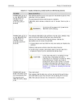
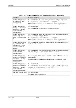
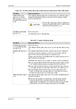
INPUT GOOD LED
(green) is on, FAULT
LED (orange) is on, and
DC GOOD LED (green)
is off
This indicates that DC output error or temperature error within the power
supply (the detected temperature was more than 60 degrees Celsius
(140°F)) was detected.
STANDBY GOOD LED
(green) is on
This is not a fault.
The disk array unit is in standby state.
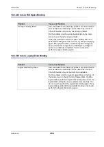
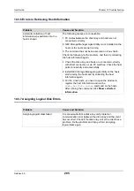
Table 10-3: Trouble in Disk Array Unit or Disk Enclosure (Rear Panel Power LED Status)
Condition
Cause and Action
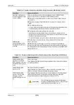
The unit has a dual power supply configuration.
Therefore, SERVICE LED turns on when FAULT
LEDs of both PS0 and PS1 are on.
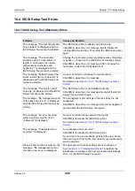
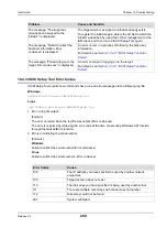
Table 10-4: Trouble in Disk Enclosure
Condition
Cause and Action
POWER LED (green) is
on, and SERVICE LED
(orange) is off
This is not a fault.
This indicates that the disk enclosure is in normal operation after turning
on.
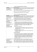
POWER LED (green) is
off
This indicates that starting the disk enclosure has not been completed.
The power of the disk enclosure is turned on in conjunction with the
power of the connected disk enclosure or disk array unit.
It takes several minutes until POWER LED of the disk enclosure turns on
after turning on the unit power.
If POWER LED does not turn on within 10 minutes, check the following.
Check whether INPUT GOOD LED of the disk enclosure power supply
is on, indicating that the power is supplied to the disk enclosure.
Check cable connection status to confirm whether this disk enclosure
is normally connected to other disk enclosures or the disk array unit.
Check POWER LED of the disk array unit to confirm whether the
power of the disk array unit was turned on. If this LED is out, check
whether the power source is functioning normally.
SERVICE LED (orange)
is on
This indicates that the disk enclosure is out of order or maintenance has
not been completed.
When the last operation is maintenance, processing such as disk
recovery may take time. Ask the maintenance personnel for the
estimated time of completion. If the disk is not recovered beyond the
estimated time, ask the maintenance personnel to investigate.
Содержание M100
Страница 25: ...Release 6 0 25 User Guide About Warning Labels Power Supply AC Power Supply ...
Страница 27: ...Release 6 0 27 User Guide About Warning Labels Battery ...
Страница 29: ...Release 6 0 29 User Guide About Warning Labels Power Cable AC Power Supply ...
Страница 40: ...Release 6 0 40 User Guide Chapter 1 Overview 1 2 1 4 Controller CONT ...
Страница 48: ...Release 6 0 48 User Guide Chapter 1 Overview 1 2 3 3 Controller CONT ...
Страница 75: ...Release 6 0 75 User Guide Chapter 3 Installing the Disk Array System Figure 3 10 Securing Unit 2 ...
Страница 88: ...Release 6 0 88 User Guide Chapter 4 NEC Storage Manager Figure 4 1 Example of Recommended Configuration ...
Страница 125: ...Release 6 0 125 User Guide Chapter 4 NEC Storage Manager d Click Login to open the main screen Figure 4 26 Main Screen ...
Страница 194: ...Release 6 0 194 User Guide Chapter 6 Initializing a Disk Array iSCSI Figure 6 16 Hot Spare Bind View Display ...
Страница 260: ...Release 6 0 260 User Guide Chapter 8 Installing Optional Parts Figure 8 12 Removing the DIMMs ...
Страница 388: ...Release 6 0 388 User Guide Appendix F How to Set Check Application Server Linux iSCSI Figure F 3 Configuration Example ...
Страница 459: ...NEC Corporation 7 1 Shiba 5 chome Minato ku Tokyo 108 8001 Japan URL http www necstorage com ...

