background image

Electra Elite IPK II

Document Revision 3

System Hardware Manual

6 - 49

___________________________________________________________________________________

___________________________________________________________________________________

5.9

DTI-U40 ETU

5.9.1

Description

The DTI-U40 ETU is a Digital Trunk ETU that terminates FT1 trunks 
(up to 24 DS-0 channels).  This ETU supports K-CCIS, ANI/DNIS 
trunks, and CSU Less Function on T1.  On-site firmware upgrade is 
supported.

A combination of Loop Start and Ground Start signaling can be used 
on the DTI-U40 ETU.  Dial Pulse dialing, DTMF, Tie line (E&M) and 
DID are supported. The DTI-U40 ETU has 24 built-in DTMF 
detectors.  Trunks are assigned in groups of four. 

When channels are assigned to ANI, the DTI-U40 ETU supports 
Feature Group D. The DTI-U40 ETU also supports Feature Group D 
incoming MF/outgoing DTMF signaling.

The DTI-U40 ETU supports the K-CCIS common channel signaling 
feature with point-to-point E&M Tie lines.

The Integrated Service Digital Network (ISDN) – Primary Rate 
Interface (PRI) is a public switched Telephone Network (PSTN) 
service that provides 23 B channels and one D (23+D) channel for 
voice call trunking.  The B channels provide 23 CO/DID connections.


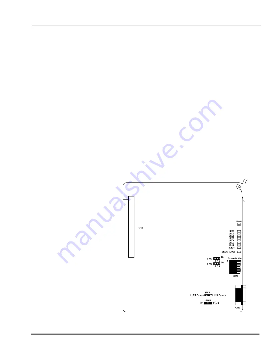
Figure 6-26  DTI-U40 ETU

Содержание ELECTRA ELITE IPK II

Страница 1: ...rmat changes may occur When viewing and printing this document we cannot guarantee that your specific PC or printer will support all of the fonts or graphics Therefore when you view the document fonts...

Страница 2: ......

Страница 3: ...SYSTEM HARDWARE MANUAL INT 1076 IPK II DOCUMENT REVISION 3 VERSION 2000...

Страница 4: ......

Страница 5: ...of NEC Unified Solutions Inc and shall not be reproduced without prior written approval of NEC Unified Solutions Inc Dterm and NEAX is a registered trademark of NEC Corporation and Electra Elite is a...

Страница 6: ......

Страница 7: ...manuals THIS MANUAL This manual contains detailed instructions to install the Electra Elite IPK II KSUs ETUs Multiline Terminals and optional equipment in the following chapters Chapter 1 Regulatory I...

Страница 8: ...his chapter contains installation instructions for Electra Elite IPK II optional equipment that can be added to the system as a customer s business grows Chapter 10 Installing Electra Elite Multiline...

Страница 9: ...K II Features and Specifications Manual This manual describes each available feature for the system Electra Elite IPK II General Description Manual This manual contains general information about the s...

Страница 10: ...THIS PAGE INTENTIONALLY LEFT BLANK...

Страница 11: ...nformation 1 1 Section 2 Company Notification 1 1 Section 3 Incidence of Harm 1 2 Section 4 Radio Frequency Interference 1 3 Section 5 Hearing Aid Compatibility 1 3 Section 6 Direct Inward Dialing 1 3...

Страница 12: ...________________________________________________________________________ ___________________________________________________________________________________ Document Revision 3 Electra Elite IPK II TH...

Страница 13: ..._________________________________ ___________________________________________________________________________________ List Of tables Chapter 1 Table 1 1 FIC REN SOC and Jacks for Electra Elite IPK II...

Страница 14: ...____________________________________________________ Document Revision 3 Electra Elite IPK II iv List of Tables ___________________________________________________________________________________ THIS...

Страница 15: ...hen such changes affect the compatibility or use of the Electra Elite IPK II system the telephone company is required to give adequate notice of the changes SECTION 2 COMPANY NOTIFICATION Before conne...

Страница 16: ...t done the telephone company may temporarily disconnect service Table 1 1 FIC REN SOC and Jacks for Electra Elite IPK II System ETUs Trunk Station ETU Type FIC REN SOC Jack BRT 4 U ETU 02IS5 N A 6 0F...

Страница 17: ...be required to correct the interference When equipped with the B64 U30 KSU and P64 U20 PSU the Electra Elite IPK II can be operated as a Class B device except when using one of the ETUs in the follow...

Страница 18: ...fication to all parties to the telephone conversation such as using a beep tone or other notification methods or require the consent of all parties to the telephone conversation prior to monitoring or...

Страница 19: ...so be installed using an acceptable method of connection The customer should be aware that compliance with the above conditions may not prevent degradation of service in some situations Repairs to cer...

Страница 20: ...lectrique edicte par Industrie Canada SECTION 12 BATTERY DISPOSAL The Electra Elite IPK II system includes the batteries listed below When disposing of these batteries KSUs and or ETUs you must comply...

Страница 21: ...l cadmium or sealed lead batteries with the municipal solid waste stream is PROHIBITED BY LAW in most areas Contact your local solid waste management officials for other information regarding the envi...

Страница 22: ...Elite IPK II system contains the following labels regarding proper disposal PRODUCT PACKAGE LABELING CONTAINS NICKEL CADMIUM BATTERY BATTERY MUST BE RECYCLED OR DISPOSED OF PROPERLY MUST NOT BE DISPOS...

Страница 23: ...______________________________________________________________________ ___________________________________________________________________________________ TABLE OF CONTENTS Chapter 2 Section 1 General...

Страница 24: ...________________________________________________________________________ ___________________________________________________________________________________ Document Revision 3 Electra Elite IPK II TH...

Страница 25: ...______________________________________________________________________________ ___________________________________________________________________________________ List of Figures Chapter 2 Figure 2 1...

Страница 26: ...____________________________________________________ Document Revision 3 Electra Elite IPK II iv List of Figures ___________________________________________________________________________________ THI...

Страница 27: ...ort size when necessary Two expansion units can be added when the CPUII U ETU is installed in the basic cabinet A full blown system includes the basic and two expansion units Electra Elite IPK II is a...

Страница 28: ...LCD A 2 line non LCD terminal and a 60 line Attendant Console are also available A customer with existing Electra Elite or Electric Elite IPK terminals can easily connect them to the Electra Elite IP...

Страница 29: ...Answering Machine External Speakerphone Headset Attendant Console CO PBX Centrex DID Tie FT1 ISDN BRI ISDN PRI Wireless DECT Electra Elite Multiline Terminal DTU Dterm Series E Multiline Terminal DTP...

Страница 30: ..._____________________________________________________ 2 4 Introduction ___________________________________________________________________________________ Document Revision 3 Electra Elite IPK II THIS...

Страница 31: ...ling Requirements and Specifications 3 22 5 2 Cabling Precautions 3 24 5 2 1 Cable Placement 3 24 5 2 2 Environmental Conditions 3 25 5 3 Power Requirements 3 25 5 3 1 Power Supply Inputs 3 25 5 3 2 P...

Страница 32: ...31 5 9 External Equipment Interface 3 35 5 9 1 Music on Hold Station Background Music 3 35 5 9 2 Music for Station BGM using Analog CO Trunk ETU COI COIB or COID 3 35 5 9 3 External Paging Audio 3 35...

Страница 33: ...for Application Interface ETUs 3 16 Table 3 5 KSU Power Based Calculator Chart 3 19 Table 3 6 Dterm Series i or Dterm IP Terminal Loop Resistance and Cable Length 3 22 Table 3 7 Electra Elite Dterm S...

Страница 34: ...______________________________________________ Document Revision 3 Electra Elite IPK II iv List of Figures and Tables __________________________________________________________________________________...

Страница 35: ...Diagram shows the ETUs that can be installed in the KSU and the number of channels supported when the ETU is installed Table 3 1 List of Abbreviations lists abbreviations used in the diagram Table 3 1...

Страница 36: ...FT1 Fractional T1 HDLC High Level Data Link Control HFU Handsfree Unit HUB Optional Hub Ethernet Interface IAD Optional Integration Device ISDN Integrated Services Digital Network LAN Local Area Netwo...

Страница 37: ...________________________________________________________ ___________________________________________________________________________________ SPK Speaker TLI Tie Line Interface VM VMP Voice Mail VoIP V...

Страница 38: ...y SLTII 1 U10 ADP SLT CPUII U ETU MOH ISDN PRI CNF 8 Conference Bridge VoIP Station Trunk COID 4 8 Wireless DECT COIB 4 8 CO Line CO Line with Caller ID AD A Tape Recorder PC CCH 4 K CCIS C Channel Ha...

Страница 39: ...8 U ETU 8 Port Conference Unit This Multiline Conference Bridge allows any intercom user or outside party calling to a port of the CNF 8 U ETU to join or make a multiparty Conference Call Each ETU sup...

Страница 40: ...U ETU CTP 12 16 U ETU This ETU is a multiplatform system that supports a maximum of 16 ports It is a PC platform that contains data storage for voice recording and application software A digital sign...

Страница 41: ...ach circuit can support any Attendant Console Multiline Terminal or Single Line Telephone adapter This ETU is installed in slots S1 S8 in the basic or expansion B64 U20 KSU The maximum number depends...

Страница 42: ...ger signal generator RSG Up to 1600 ohms of resistance including the Single Line instrument is acceptable between the OPX ETU and the Single Line Telephone This ETU is installed in slots S1 S8 in any...

Страница 43: ...provides a built in ringer signal generator RSG and Message Waiting MW LED voltage to Single Line Telephones This ETU is installed in slots S1 S8 in any B64 U20 KSU The maximum number depends on other...

Страница 44: ...his ETU as a VMS 8 U ETU This ETU shares the total number of station ports in the system 1 1 Notes 1 3 4 6 VP 4 8 U System ETU This 4 or 8 Port Digital Voice Mail System has ports that support TeLANop...

Страница 45: ...aximum port capacity Note 3 Only one CMS FMS VMS VP CTI CTP IVR system can be installed in one Electra Elite IPK II system Note 4 A maximum of 32 Digital Voice Mail ports are available Note 5 Two phys...

Страница 46: ...m 7 23 Notes 1 6 COI 4 U ETU This 4 Port CO PBX Line Interface has built in fuses posistors supports four outside CO PBX lines and provides circuitry for ring detection holding and dialing The outside...

Страница 47: ...the system Tip and Ring electrical fuses are provided to comply with UL 1459 requirements 14 23 Notes 1 3 COIB 8 U ETU 8 Port CO PBX Line Interface can function the same as the COI 4 or COID 4 ETU to...

Страница 48: ...Interface or ISDN Primary Rate digital trunk terminates Fractional T1 trunks Up to 24 DS 0 channels This ETU supports K CCIS ANI DNIS trunks and CSU less function on T1 A combination of ground start a...

Страница 49: ...14 23 Note 2 Note 1 Calculating maximum capacity is based on the system having a minimum of eight Electronic Station Interface ESI ports four Trunk ports and a PKUII U Unit installed Note 2 When 2 po...

Страница 50: ...is ETU is installed in the first or second slot to the left of the BSU 4 U20 ETU 2 2 Notes 1 2 BSU 6S U20 ETU This Slave 6 Base Station Unit for Wireless DECT has connections for six Base Stations and...

Страница 51: ...her Using the MG_CCIS Combo Package 4 port license registration provides user with the flexibility of adding CCISoIP ports in increments of four 4 8 12 16 20 or 24 or MG16 DSP resources in increments...

Страница 52: ...inet can contain a maximum of nine cards J The total point value cannot exceed 1000 points for 5V J The total point value cannot exceed 1000 points for 24V To calculate the two values 5V and 24V for a...

Страница 53: ...CF ETU 7 0 EXP U10 ETU 6 0 MOD U10 Unit 25 0 Trunk BRT 4 U ETU 67 0 COI 4 U10 ETU 48 5 COI 8 U10 ETU 82 9 COID 8 U ETU 55 9 COIB 4 U20 ETU 29 5 COIB 4 U30 ETU 29 5 COIB 8 U30 ETU 54 9 DID 4 U ETU 24...

Страница 54: ...S 4 U30 ETU 55 68 FMS 8 U30 ETU 81 68 VMS 4 U30 ETU 55 96 VMS 8 U30 ETU 80 100 VMS 4 U40 ETU 55 96 VMS 8 U40 ETU 80 100 FMS 2 U40 ETU 55 68 FMS 4 U40 ETU 55 68 FMS 8 U40 ETU 81 68 VP CTI IVR 8 U10 ETU...

Страница 55: ...ator Chart is shown below SAMPLE CALCULATION USING KSU POWER BASED CALCULATOR CHART Package Quantity Total Power Consumption 5V value from Chart Total Power Consumption 24V value from Chart Basic Cabi...

Страница 56: ...nd Cable Length Refer to Table 3 8 Cable Connection Between the Analog Port and the Single Line Equipment Refer to Table 3 9 Cabling Requirements Table 3 6 Dterm Series i or Dterm IP Terminal Loop Res...

Страница 57: ...AWG DTU 8 1 TEL DTP 8 1 TEL 35 600 1000 DTU 8D 2 TEL DTP 8D 1 TEL 35 600 1000 DTU 16 1 TEL DTP 16 1 TEL 26 450 900 DTU 16D 2 TEL DTP 16D 1 TEL 26 450 900 DTP 16HC 1 TEL 57 1083 DTU 32 1 TEL DTP 32 1...

Страница 58: ...o vibration Table 3 8 Cable Connection Between the Analog Port and the Single Line Equipment Connected Equipment Cable Maximum Distance or Impedance Between Equipment and Telephone AD A R AD A 2R Unit...

Страница 59: ...1 Power Supply Inputs AC input requirements for the system are listed below AC Input P64 U PSU J 117 Vac 10 J 60 Hz 10 J Single Phase J 7 5A circuit J A dedicated outlet separately fused and grounded...

Страница 60: ...runks J ISDN PRI Trunks J VoIP Trunks Internet Protocols Refer to Table 1 1 FIC REN SOC and Jacks for Electra Elite IPK II System ETUs in the Regulatory Information section in this manual for a detail...

Страница 61: ...timeframe J TDM Switching PCM Law J TDM Clock 2 048 MHz J TDM Data Bus 8 bit J TDM Timeframe 125 s 5 5 3 Control This section indicates the speed or capacity J Control Stored program with distributed...

Страница 62: ...et 500 type network Nominal Current 30 mA Ring Signal 56 Vac RMS 20 Hz J AP A R Unit Standard 2500 Set 500 type network Nominal Current 30 mA J AP R R Unit Standard 2500 Set 500 type network Nominal C...

Страница 63: ...l 0 pps 20 pps 500 ms 800 ms 5 6 2 Dual Tone Multifrequency DTMF Address Signaling DTMF signaling describes push button or Touchtone dialing When a key on a telephone is pushed two tones one high freq...

Страница 64: ...ked up using a rechargeable battery This battery backup supports all of the system operations for approximately 30 minutes 5 7 2 Memory Backup The CPUII U ETU battery retains the Clock Calendar and La...

Страница 65: ...8 75 mm 5 5 137 5 mm AP A R Unit 5 6 oz 158 g 2 25 56 25 mm 2 75 68 75 mm 5 5 137 5 mm AP R R Unit 5 6 oz 158 g 2 25 56 25 mm 2 75 68 75 mm 5 5 137 5 mm B64 U20 KSU 460 8 oz 13063 g 13 0 328 7 mm 14 0...

Страница 66: ...5 mm CT A R Unit 4 0 oz 113 g 2 25 56 25 mm 2 75 68 75 mm 5 5 137 5 mm CTA U Unit 4 3 oz 122 g 2 4 60 mm 2 3 59 mm 4 8 121 mm CTI VP 4 8 12 16 U ETU 192 oz 2 5443 g 1 89 48 mm 11 47 290 mm 8 46 214 mm...

Страница 67: ...D 2 TEL DTP 16D 1 TEL 43 5 oz 1233 g 4 8 123 mm 7 8 197 mm 9 3 235 mm DTP 16HC 1 TEL 53 oz 1503 g 6 00 152 mm 9 08 230 mm 8 04 204 mm DTP 2DT 1 TEL 41 oz 1163 g 4 8 123 mm 7 8 197 mm 9 3 235 mm DTU 32...

Страница 68: ...m 8 46 214 mm HF R Unit 9 9 oz 280 g 2 9 74 mm 4 2 106 mm 5 6 141 mm HUB 8 U ETU 10 4 oz 294 g 1 97 50 mm 9 45 240 mm 7 68 195 mm IAD 8 U ETU 8 11 oz 230 g 7 5 190 mm 6 3 160 mm 0 87 22 mm ITH 8D 2 3...

Страница 69: ...0 6 V PPS Signal Level J Input Impedance 600 5 9 3 External Paging Audio J Output Power 10 dBm Signal Level J Output Impedance 600 J Relay Contact Rating 500 mA 24 Vdc SLIB 4 U10 ETU 13 0 oz 370 g 1 9...

Страница 70: ...System Output Standard DB 9 straight 5 9 8 Relay Contact J All Relay Contact Ratings 500 mA 24 Vdc 5 10 Audible and Visual Indications The tables in this section provide the audible and visual indica...

Страница 71: ...Dial Tone 350 440 Continuous Internal Ringback Tone 440 480 1 sec On 2 sec Off LCR Dial Tone 440 Continuous Reorder Tone 480 620 120 IPM Service Set Tone 440 Continuous Special Dial Tone 440 240 IPM...

Страница 72: ...ne ON Red I ON Series i Red ICM I Use ICM Incoming Call Voice Over Broker Red Red Red Large LED Incoming Internal Call Incoming Outside Call Message from Attendant Voice Mail Message Red Green Green R...

Страница 73: ..._________________________________________________________________________ SECTION 6 TRAFFIC CAPACITY Table 3 15 Traffic Capacity provides information about the traffic capacity for the Basic Port Pack...

Страница 74: ...________________________________________________ 3 40 System Specifications ___________________________________________________________________________________ Document Revision 3 Electra Elite IPK II...

Страница 75: ...Section 1 General Information 4 1 Section 2 Programming Stations 4 1 Section 3 Attendant Stations 4 1 Section 4 Programming from a PC 4 1 Section 5 Programming from a Multiline Terminal 4 2 Section 6...

Страница 76: ...________________________________________________________________________ ___________________________________________________________________________________ Document Revision 3 Electra Elite IPK II TH...

Страница 77: ...______________________ ___________________________________________________________________________________ List of Figures and Tables Chapter 4 Figure 4 1 Interface Slot and System Port Numbers for an...

Страница 78: ...______________________________________________ Document Revision 3 Electra Elite IPK II iv List of Figures and Tables __________________________________________________________________________________...

Страница 79: ...equires a display multiline terminal SECTION 3 ATTENDANT STATIONS Any display Multiline Terminal can be programmed as an Attendant position in the Electra Elite IPK II system An Attendant Position can...

Страница 80: ...s required SECTION 6 ELECTRA ELITE IPK II REMOTE PC PROGRAMMING The Electra Elite IPK II system can be programmed from a remote location using a personal computer 6 1 Remote Programming To provide rem...

Страница 81: ...DTH 8D 1 TEL DTR 8D 1 TEL DTU 8D 2 TEL ITH 8D 2 TEL 8 line digital Multiline Terminal with LCD and softkeys DTP 16 1 TEL DTU 16 1 TEL DTH 16 1 TEL 16 line digital Multiline Terminal without LCD DTP 1...

Страница 82: ...le speed dial buttons and Hold and Monitor keys DTR 1R 1 TEL Dterm Multiline Cordless Telephone without LCD DTR 4R 1 2 TEL Dterm Multiline Cordless Telephone with LCD DTH 4R 1 2TEL Dterm Multiline Cor...

Страница 83: ...dicates how the CO and trunk numbers can be used The following ETUs are installed for the Figure 4 2 Telephone and CO Port Numbering Example Slot ETU S1 DTI U All 24 channels count against the system...

Страница 84: ...________________________________________________ 4 6 Hardware Requirements ___________________________________________________________________________________ Document Revision 3 Electra Elite IPK II...

Страница 85: ...lecting a Permanent MDF Location 5 2 2 3 3 Selecting a Site for Installing the Telephones 5 3 2 4 Constructing the Main Distribution Frame MDF 5 3 2 5 Power Failure Transfer 5 8 2 6 Fax CO Branch Conn...

Страница 86: ...ounding Requirements 5 21 3 10 Replacing the Power Supply Unit in the KSU 5 23 3 10 1 Connecting the Power Supply Unit to the Basic KSU 5 23 3 10 2 Connecting Battery Expansion Cables to the Expansion...

Страница 87: ...Amphenol Cables 5 12 Figure 5 7 Attaching the Wall Mount Bracket 5 12 Figure 5 8 Attaching the Wall Mount Bracket with Spacer 5 13 Figure 5 9 Hanging the Basic KSU on the Bracket 5 13 Figure 5 10 Sec...

Страница 88: ...27 Figure 5 28 Placing the Batteries into the KSU 5 28 Figure 5 29 Connecting the Batteries to the Power Supply Unit 5 28 Figure 5 30 Connecting Cables for External Batteries in the Basic KSU 5 29 Fig...

Страница 89: ...me cost and disruption of the customer business activities 2 1 Precautionary Information 1 Never install telephone wiring during a lightning storm 2 Never install telephone jacks in wet locations unle...

Страница 90: ...mmable gases excessive chemical or industrial dusts and other materials that could cause a hazard to personnel or to the proper functioning of the equipment J The operating ambient temperature and hum...

Страница 91: ...op Resistance and Cable Length on page 3 23 J Select a place where devices that require an external power supply can be easily connected to an AC outlet 2 4 Constructing the Main Distribution Frame MD...

Страница 92: ...is connected to each of the Multiline Terminals Single Line Telephones optional equipment CO PBX DID ISDN 4 wire E M Tie lines Types I and V and FT1 digital trunks by separate twisted pair cable thro...

Страница 93: ...H BR GN T T T T T T T1 1 RA 2 4 BR WH RD R R R R R R R1 1 RB 2 30 WH SL GN T T T GND TA 3 5 SL WH RD R R R TB 3 31 RD BL GN T T T E 2 RA 3 6 BL RD RD R R R M 2 RB 3 32 RD OR GN T T T T 2 TA 4 7 OR RD...

Страница 94: ...19 BR YL RD R R R R R R R 1 TB 2 45 YL SL GN T T T T T T T1 1 RA 2 20 SL YL RD R R R R R R R1 1 RB 2 46 VI BL GN T T T GND TA 3 21 BL VI RD R R R TB 3 47 VI OR GN T T T E 2 RA 3 22 OR VI RD R R R M 2...

Страница 95: ...ion 42 PFT1 CO Tip Power Failure Transfer Relay 1 Amp 3 Connections Only 17 PFT1 CO Ring 43 PFT1 SLI Tip 18 PFT1 SLI Ring 44 PFT1 SLT Tip 19 PFT1 SLT Ring 45 PFT2 CO Tip 20 PFT2 CO Ring 46 PFT2 SLI Ti...

Страница 96: ...e KSU When selecting a Single Line Telephone for power failure transfer make sure it matches the CO line dialing type 10 pps 20 pps or DTMF where it is connected A Single Line Telephone with a ground...

Страница 97: ...ed SECTION 3 INSTALLING BASIC AND EXPANSION KSUS The compact design of the Electra Elite IPK II KSU provides easy installation The KSUs can be floor mounted or rack mounted Only the Basic KSU can be f...

Страница 98: ...nit backup batteries and three PFT relays are included with each KSU 3 1 2 Expansion KSUs The B64 U20 KSU is also used as the expansion unit that can be attached to the basic KSU to provide additional...

Страница 99: ...uring Cables Using the Velcro Strap Amphenol cables attached to the side of the KSU can be secured using the provided velcro strap When wall mounting this should be done prior to attaching the KSU to...

Страница 100: ...ree amphenol cables are used the velcro strap is threaded around the cables instead of through the hooks and attached to the KSU 3 4 Wall Mounting the Basic KSU 1 Before wall mounting the KSU use the...

Страница 101: ...l off the spacer backing Place and adhere the spacer to the position shown in Figure 5 8 Attaching the Wall Mount Bracket with Spacer All wall and rack mounted KSUs must have the Spacer Bracket added...

Страница 102: ...________________________________________________________ Document Revision 3 Electra Elite IPK II 4 Secure the KSU to the wall by placing a locally provided screw and washer in the hole in the center...

Страница 103: ...he Basic Wall Mount Bracket Refer to Figure 5 11 Attaching the Expansion Wall Mount Bracket to the Basic Wall Mount Bracket 2 Hang the KSU on the two hooks protruding from the expansion wall mount bra...

Страница 104: ...the RAK U Unit to the equipment rack using the six provided screws Refer to Figure 5 12 RAK U Unit and KSU Use three screws on the right side at 1 2 and 3 and three screws on the left side 2 Mount the...

Страница 105: ..._________ ___________________________________________________________________________________ 4 Secure the KSU to the RAK U Unit by installing a provided screw into the KSU tab and bracket hole A2 Ref...

Страница 106: ...mounting the Basic KSU and the Expansion KSUs 2 The Basic KSU is installed in the lower position of the rack mounting bracket The Basic KSU is secured using the five threaded screw holes marked A 3 Th...

Страница 107: ...expansion KSU can be floor mounted 1 Use the four locally provided screws to attach the floor mount bracket to the floor 2 Slide the KSU over the four hooks protruding from the floor mount bracket as...

Страница 108: ...necting the Battery Expansion Cables on the KSU 1 Use the DC Expansion Cable included with the EXP U ETU to connect the BATTERY EXT on the Basic KSU to the BATTERY EXT of the Expansion KSU 2 To connec...

Страница 109: ...______ 3 9 2 Grounding Requirements The KSUs must be properly grounded The Electra Elite IPK II KSUs are provided with a typical AC third wire ground When this ground is questionable an alternative gr...

Страница 110: ...___________________________________ Document Revision 3 Electra Elite IPK II 2 Provide a suitable ground inside of a building in accordance with local telephone company procedures 3 When no suitable g...

Страница 111: ...s a battery backup interface and accepts 117 Vac and outputs 5V and 24V to the system The Power Supply Unit is included with the B64 U20 KSU 3 10 1 Connecting the Power Supply Unit to the Basic KSU 1...

Страница 112: ...________________________________________________ Document Revision 3 Electra Elite IPK II 3 Lead the KSU power cable through the clamp and connect the PSU as shown in Figure 5 23 Connecting the PSU Po...

Страница 113: ...2 Connecting Battery Expansion Cables to the Expansion KSU 1 Lead the Battery Expansion Cables included with the EXP U ETU through the clamps and tie them to the KSU with a tie wrap on the expansion...

Страница 114: ...on the KSU Refer to Figure 5 4 Removing the Front Panel of the KSU 2 Pull out the drawer that holds the PSU and disconnect the cable as shown in Figure 5 25 Removing the PSU from the KSU 3 Replace th...

Страница 115: ...1 Built In Battery Installation 1 Connect the two batteries in series as shown in Figure 5 27 Connecting Built In Batteries The red cord attaches to the red terminal and the black cord attaches to the...

Страница 116: ..._____ Document Revision 3 Electra Elite IPK II 3 Install the battery cover as illustrated in Figure 5 28 Placing the Batteries into the KSU 4 Connect the cable to the BATTERY INT connector of the PSU...

Страница 117: ...nal batteries 3 11 2 1 Basic KSU 1 Connect cabling to the external batteries as shown in Figure 5 30 Connecting Cables for External Batteries in the Basic KSU Figure 5 30 Connecting Cables for Externa...

Страница 118: ...2 Connect the external batteries to the KSU in the location shown in Figure 5 31 Connecting the External Battery to the Basic KSU Connect the external battery cable to the EXT connector on the PSU of...

Страница 119: ...___________________________________________________________________________ 4 Before putting the cover on the Basic KSU remove the knockout indicated by the arrow Refer to Figure 5 33 Removing the Kno...

Страница 120: ...KSU 3 11 2 2 Expansion KSU When connecting batteries to the Expansion KSUs connections that must also be made to the Basic KSU are noted in the following instructions Although a 3 cabinet drawing is...

Страница 121: ...________________________________________________________ 2 Connect the external battery cable to the EXT connector on the PSU of the Basic KSU and the Expansion KSUs as shown in Figure 5 35 External B...

Страница 122: ...________________________________________________________ Document Revision 3 Electra Elite IPK II 3 Route the cables through the clamps on the Basic and Expansion KSUs as shown in Figure 5 36 Threadin...

Страница 123: ...______________ 4 Before putting the covers on the Basic and Expansion KSUs remove the knockouts indicated by the arrows On the Basic KSU knockouts must be removed from the top and the bottom of the KS...

Страница 124: ..._____________________________________ Document Revision 3 Electra Elite IPK II 5 Lead the battery cables through the knockouts on the Basic and Expansion KSUs and secure the front covers on the KSUs R...

Страница 125: ...4 2 3 Removing an ETU from the KSU 6 6 Section 3 Powering Up the Elite IPK II 6 7 Section 4 Common Control ETUs 6 8 4 1 CPUII U10 ETU 6 8 4 1 1 Description 6 8 4 1 2 Installation 6 8 4 1 3 Switch Sett...

Страница 126: ...5 LED Indications 6 22 5 1 6 Connectors 6 23 5 1 7 Connections 6 23 5 2 BRT 4 U20 ETU 6 24 5 2 1 Description 6 24 5 2 2 Installation 6 25 5 2 3 Switch Settings 6 25 5 2 4 Jumpers 6 25 5 2 5 LED Indic...

Страница 127: ...5 5 Connectors 6 37 5 5 6 Connections 6 38 5 5 7 ETU Feature Chart 6 38 5 6 COIB 8 U20 U30 ETU 6 39 5 6 1 Description 6 39 5 6 2 Installation 6 40 5 6 3 Switch Settings 6 40 5 6 4 LED Indications 6 4...

Страница 128: ...9 6 Connectors 6 55 5 9 7 Connections 6 55 5 10 TLI 2 U ETU 6 57 5 10 1 Description 6 57 5 10 2 Installation 6 58 5 10 3 Switch Settings 6 58 5 10 4 LED Indications 6 59 5 10 5 Connectors 6 59 5 10 6...

Страница 129: ...cations 6 68 6 3 6 Connectors 6 68 6 3 7 Connections 6 69 6 4 ESIE 8 U10 ETU 6 70 6 4 1 Description 6 70 6 4 2 Installation 6 71 6 4 3 Connectors 6 71 6 4 4 Connections 6 72 6 4 5 Pin Assignments 6 72...

Страница 130: ...6 8 6 Connections 6 86 6 9 SLIE 4 U10 ETU 6 87 6 9 1 Description 6 87 6 9 2 Installation 6 88 6 9 3 Connectors 6 88 6 9 4 Connections 6 89 Section 7 Voice Mail ETUs 6 90 7 1 CMS 2 4 U ETUCMS 2 4 U ET...

Страница 131: ...ving the CTP U10 ETU 6 110 7 3 8 Switch Settings 6 111 7 3 9 LED Indications 6 111 7 3 10 Connectors 6 111 7 4 FMS 2 4 8 U ETU 6 112 7 4 1 Description 6 112 7 4 2 Installation 6 115 7 4 3 Switch Setti...

Страница 132: ...ETU Jumper Settings 6 142 7 6 7 VMS U30 ETU Connectors 6 142 Section 8 Optional ETUs 6 143 8 1 BSU 4M U20 ETU 6 143 8 1 1 Description 6 143 8 1 2 Installation 6 144 8 1 3 LED Indications 6 145 8 1 4 C...

Страница 133: ...158 8 6 CNF 16 U20 ETU 6 159 8 6 1 Description 6 159 8 6 2 Installation 6 161 8 6 3 Configuring 6 161 8 6 4 LED Indications 6 163 8 6 5 Connectors 6 164 8 7 HUB 8 U ETU 6 165 8 7 1 Description 6 165...

Страница 134: ..._________________________ Document Revision 3 Electra Elite IPK II 8 9 4 LED Indications 6 172 8 9 5 Jumper Settings 6 173 8 9 6 Connectors 6 174 8 10 PVA X U ETU 6 175 8 10 1 Description 6 175 8 10 2...

Страница 135: ...ing the Ejector Tabs on the ETU 6 6 Figure 6 7 CPUII U10 ETU 6 9 Figure 6 8 EXP U ETU 6 18 Figure 6 9 MOD U10 Unit 6 19 Figure 6 10 BRT 4 U10 ETU 6 20 Figure 6 11 BRT 4 U ETU Connections 6 23 Figure 6...

Страница 136: ...e 6 33 ESIB 8 U ETU 6 63 Figure 6 34 ESIB 8 U ETU Connection 6 65 Figure 6 35 ESIB 8 U20 6 66 Figure 6 36 ESIB 8 U20 Connection 6 69 Figure 6 37 ESIE 8 U ETU 6 70 Figure 6 38 ESIE 8 U ETU Connection 6...

Страница 137: ...ETU 6 109 Figure 6 62 Insert Brass Connector End 6 109 Figure 6 63 Push Other End Down Until it Locks 6 110 Figure 6 64 FMS 2 4 U ETU 6 113 Figure 6 65 FMS 8 U ETU 6 114 Figure 6 66 FMS U30 ETU 6 115...

Страница 138: ..._______________________________________________________________________________ Figure 6 81 BSU 6S U20 ETU 6 149 Figure 6 82 CCH 4 U ETU 6 152 Figure 6 83 CNF 8 U ETU 6 155 Figure 6 84 CNF 16 U20 ETU...

Страница 139: ...COIB 4 U 10 ETU Default Switch Settings 6 33 Table 6 10 COIB 4 U 10 ETU LED Indications 6 34 Table 6 11 COIB 4 U20 ETU Default Switch Jumper Settings 6 36 Table 6 12 COIB 4 U20 ETU LED Indications 6 3...

Страница 140: ...6 99 Table 6 35 Daughter Board Components 6 101 Table 6 36 Port Expansion Board Components 6 102 Table 6 37 Configuration Support Table 6 112 Table 6 38 FMS 2 4 8 U ETU Switch Settings 6 116 Table 6 3...

Страница 141: ...W1 6 162 Table 6 59 CNF 16 U20 ETU Rotary Switch SW3 6 162 Table 6 60 CNF 16 U20 ETU LED Indications 6 163 Table 6 61 HUB 8 U LEDS 6 166 Table 6 62 IAD 8 U Configurations 6 168 Table 6 63 IAD 8 U ETU...

Страница 142: ...___________________________________________________ Document Revision 3 Electra Elite IPK II xviii List of Tables ___________________________________________________________________________________ TH...

Страница 143: ...Slot J AP Slot Not Used J Interface IF Slot CPU EXP Slot This is the first slot from the left in the KSU A CPUII U10 ETU must be installed in this slot in the Basic KSU and an EXP U10 ETU must be inst...

Страница 144: ...oid static discharge when handling ETUs J Make all switch setting changes on the ETU before inserting it in the KSU J When installed the component side of all ETUs must face the left side of the KSU E...

Страница 145: ...you insert or remove an ETU be sure the wrist strap is connected to the Frame Ground Terminal on the KSU J When you hold an ETU do not touch the components or the soldered surfaces with bare hands Pl...

Страница 146: ...screw driver can be used to change the switch settings when the installer follows the recommended safety precautions 2 2 Inserting an ETU into the KSU Slots 1 To unlock the ETUs slots move the slide b...

Страница 147: ...System Hardware Manual 6 5 ___________________________________________________________________________________ ___________________________________________________________________________________ Figu...

Страница 148: ..._____________________________________________________ Document Revision 3 Electra Elite IPK II 2 3 Removing an ETU from the KSU 1 To unlock the ETUs move the slide bar to the left 2 Lift the ejector t...

Страница 149: ...d the LOAD button on the CPUII U10 ETU Turn the system power ON while continuing to hold the LOAD button 3 After approximately five seconds or when the Live LED starts to flash release the LOAD button...

Страница 150: ...o and from other ETUs This ETU provides the following items J Time Switch Control 512 CH J Digital Phase Lock Loop DPLL J Static Random Access Memory SRAM J DSPII U10 Daughter Board J 32 bit Processor...

Страница 151: ..._______________________________________________ ___________________________________________________________________________________ 4 1 3 Switch Settings Refer to Table 6 1 CPUII U10 Default Switch Se...

Страница 152: ...lure occurs and the battery backup circuit is not activated Time and Date Terminal status e g MIC and SMDR Data are reset System data is not lost due to the battery backup circuit When a CPUII U10 ETU...

Страница 153: ...system alarms Refer to Table 6 3 CPUII U10 Status LED4 Indicates system alarms Refer to Table 6 3 CPUII U10 Status LED5 LIVE On indicates the PKG is operating The LEDs are on the back of the ETU in th...

Страница 154: ...Initialization 1 Turn off the KSU power 2 Remove the CPUII U10 ETU from the KSU 3 Remove the battery from connector CN6 4 Install new CR2032 battery in CN6 5 Install the CPUII U10 ETU in the KSU 6 Tu...

Страница 155: ...using an expansion cable J CN4 LAN connector J CN5 Compact Flash connector J CN6 Holds the Lithium CR2032 Battery J CN7 DSPII U10 Daughter Board connector J CN8 Used for FPGA Programming J CN9 Normal...

Страница 156: ...K II PCPro 3 Login to PCPro The default login is tech with a password of 12345678 4 Connect to IPK II by selecting Connect from the toolbar or selecting Connect from the Communications Menu 5 Define t...

Страница 157: ...ion that the CPU used to boot from The other version is the new version that is used on the next boot up If boot up fails the CPU can revert back to the older version 14 To verify if the system was up...

Страница 158: ...il the update is complete 11 After the upload is complete a complete message is displayed in the WebPro browser window When immediately is selected for the Schedule Update section reset and switching...

Страница 159: ...UP file 3 Rename this file to BATCH64 TXT 4 Perform the Upgrading from Compact Flash procedure 4 2 PKUII U Port Key Unit When the Port Key Unit is installed the system has an Expanded Port Package Whe...

Страница 160: ...___________________________________________________________________ Document Revision 3 Electra Elite IPK II 4 3 EXP U ETU 4 3 1 Description The EXP U ETU is the Expansion KSU Controller This ETU cont...

Страница 161: ...ected to CN3 on the CPUII U10 ETU or CN3 on EXP U ETU installed in the first expansion cabinet using an expansion cable J CN3 Connected to CN2 on the EXP U ETU installed in the third expansion cabinet...

Страница 162: ...the interface slots of the KSU 5 1 BRT 4 U ETU 5 1 1 Description The Basic Rate Trunk BRT Interface ETU terminates ISDN Basic Rate Trunk lines and supports four ISDN BRI circuits Each trunk supports t...

Страница 163: ...age A maximum of 23 BRT 4 U ETUs can be installed in any interface slot in the system The system limitation is 200 trunks The maximum number of BRT 4 U ETUs depends on other trunk cards installed This...

Страница 164: ...ription On Flashing Off LED 1 ETU status Operation stopped Power On Normal Operation No Power LED 2 L1 status BRI CKT1 L1 working Not Used L1 idle LED 3 L1 status BRI CKT2 L1 working Not Used L1 idle...

Страница 165: ...________________________________ 5 1 6 Connectors The following connector is included J CN1 Connects to the backplane 5 1 7 Connections Figure 6 11 BRT 4 U ETU Connections Network and CO TELCO U Inter...

Страница 166: ...asic Rate Trunk BRT Interface ETU terminates ISDN Basic Rate Trunk lines and supports four ISDN BRI circuits Each trunk supports two B channels These eight B channels can be used for CO trunks with DT...

Страница 167: ...d Expanded Port Package A maximum of 23 BRT 4 U20 ETUs can be installed in any interface slot in the system The system limitation is 200 trunks The maximum number of BRT 4 U20 ETUs depends on other tr...

Страница 168: ...Indications Refer to Table 6 6 BRT 4 U20 ETU LED Indications 5 2 6 Connectors The following connectors are included J CN1 Connects to the backplane J CN3 DB9 Pin Male connector used for maintenance T...

Страница 169: ...__________________________________________________________________________ 5 2 7 Connections Figure 6 13 BRT 4 U20 ETU Connections Network and CO TELCO U Interface 2 Wire NT1 NT1 ST 4 Wire ST 4 Wire M...

Страница 170: ...ice interface The COI ETU contains circuitry for outside ring detection holding dialing and control functions This ETU can provide a CAMA trunk for Enhanced E911 The COI 8 U ETU has identical circuits...

Страница 171: ...onic Station Interface ESI ports four trunk ports and a PKUII U Unit installed Expanded Port Package A maximum of 23 COI 4 U ETUs or 23 COI 8 U ETUs can be installed in any interface slot The system l...

Страница 172: ...uded J CN1 Connects to the backplane Table 6 8 COI 8 U ETU LED Indications LED Description On Flashing Off LIVE ETU status Operation stopped Power On Normal Operatio n No Power LED 1 Line 1 status COI...

Страница 173: ...________ ___________________________________________________________________________________ 5 3 6 Connections Figure 6 15 COI 4 8 U ETU Connections MDF T 1 R 1 T 2 R 2 T 3 R 3 T 4 R 4 T 5 R 5 T 6 R 6...

Страница 174: ...D 4 U ETU to provide a Central Office interface When the ETU is set for COID mode Loop Start trunks and or Caller ID trunks are supported When the ETU is set for COI mode Loop Start or Ground Start is...

Страница 175: ...I U Unit installed Expanded Port Package A maximum of 23 COIB 4 U 10 ETUs can be installed in any interface slot when configured as either a COI COID ETU The system is limited by 200 trunks The maximu...

Страница 176: ...ane J CN2 Future J CN3 Future 5 4 6 Connections Table 6 10 COIB 4 U 10 ETU LED Indications LED Description On Flashing Off LIVE ETU status Operation stopped Power On Normal Operation No Power LED 1 CH...

Страница 177: ...COIB 4 U30 can support the CO Message Waiting Indication feature These ETUs have transmit and receive pad controls When the ETU is set for COID mode Loop Start trunks and Caller ID trunks are support...

Страница 178: ...t Package A maximum of 23 COIB 4 U20 ETUs can be installed in any interface slot when configured as either a COI COID ETU The system is limited by 200 trunks The maximum number of COIB 4 U20 ETUs depe...

Страница 179: ...ckplane J CN2 Future J CN3 Future S1 Open for COI Shorted default for COID Selects COIB 4 U20 ETU COI or COID mode Reset Toggle Resets the COIB 4 U20 ETU Table 6 12 COIB 4 U20 ETU LED Indications LED...

Страница 180: ...ID See Note CO Message Waiting Indicate Pad Control Loop Start Ground Start Fax Branch CAMA Trunk COI 4 U10 X X X COI 8 U10 X X X COID 4 U10 X X X X COID 8 U10 X X X COIB 4 U10 X X X X X COIB 4 U20 X...

Страница 181: ...Feature Transmit and receive pad controls have been added to the COIB 8 U20 U30 ETU When the ETU is set for COID mode Loop Start trunks and Caller ID trunks are supported When the ETU is set for COI m...

Страница 182: ...imum of 23 COIB 8 U20 U30 ETUs can be installed in any interface slot when configured as COI ETUs The system is limited by 200 trunks The maximum number of COIB 8 U20 U30 ETUs depends on other trunk c...

Страница 183: ...Resets the COIB 8 U20 U30 ETU Table 6 15 COIB 8 U20 30 ETU LED Indications LED Description On Flashing Off LIVE ETU status Operation Stopped Power On Normal Operation No Power LED 1 Channel 1 status...

Страница 184: ...Note CO Message Waiting Indicate Pad Control Loop Start Ground Start Fax Branch CAMA Trunk COI 4 U10 X X X COI 8 U10 X X X COID 4 U10 X X X X COID 8 U10 X X X COIB 4 U10 X X X X X COIB 4 U20 X X X X...

Страница 185: ..._________ 5 7 COID 4 8 U ETU 5 7 1 Description The COID 4 8 U ETU is the Central Office interface for Caller ID Detection This ETU provides circuitry for outside ring detection hold dialing Caller ID...

Страница 186: ...lled Expanded Port Package A maximum of 23 COID 4 U ETUs or 23 COID 8 U ETUs can be installed in any interface slot The system limitation is 200 trunks The maximum number of COID 4 8 U ETUs depends on...

Страница 187: ...nnects to the backboard 5 7 6 Connections LED 6 Line 6 status COID 8 Busy Not Used Idle LED 7 Line 7 status COID 8 Busy Not Used Idle LED 8 Line 8 status COID 8 Busy Not Used Idle Table 6 17 COID 4 8...

Страница 188: ..._____________________________ Document Revision 3 Electra Elite IPK II 5 8 DID 4 U ETU 5 8 1 Description The Direct Inward Dialing Interface Unit supports up to four DID or four 2 way DID lines Each D...

Страница 189: ...Expanded Port Package A maximum of 23 DID 4 U ETUs can be installed in slots S1 S8 The maximum number of DID 4 U ETUs depends on other trunk cards installed This ETU shares the total number of CO PBX...

Страница 190: ...___ 6 48 Installing ETUs Circuit Cards ___________________________________________________________________________________ Document Revision 3 Electra Elite IPK II 5 8 5 Connections Figure 6 25 DID 4...

Страница 191: ...signaling can be used on the DTI U40 ETU Dial Pulse dialing DTMF Tie line E M and DID are supported The DTI U40 ETU has 24 built in DTMF detectors Trunks are assigned in groups of four When channels a...

Страница 192: ...es the CO PBX lines in the system Calculating maximum capacity is based on the system having a minimum of eight Electronic Station Interface ESI ports four trunk ports and a PKUII U Unit installed Exp...

Страница 193: ...CH17 CH24 indication ON Used SW1 4 ON DS 1 Mode T1 with CSU Function external CSU not required OFF DSX 1 Mode T1 without CSU Function external CSU required When the system is connected behind an exte...

Страница 194: ...ance and loss characteristics SW1 7 SW18 When SW1 4 is ON SW1 7SW1 8 OFF OFF Normal Mode Default ON OFF Line Loop Back Mode OFF ON DTE Loop Back Mode ON ON Local Loop Back Mode In Local Loop Back data...

Страница 195: ...OFF No operation Default SW3 3 ON To be determined OFF No operation Default SW3 4 ON To be determined OFF No operation Default The DTI U40 works only with the SW3 2 SW3 4 Default settings SW4 5 SW4 S...

Страница 196: ...gnal exceeds the buffering ability of the terminal J Cyclic Redundancy Check CRC Error Event Detection On red when a CRC Error occurs Table 6 20 DTI U40 ETU LED Indications LED SW1 1 OFF With SW1 1 ON...

Страница 197: ...F Condition Detection On red when two of the four or five framing data bits received are in error J Remote Alarm Indication RAI Detection On red when RAl is received 5 9 6 Connectors The following con...

Страница 198: ...6 28 ISDN PRI Connectors Table 6 21 DTI Configurations DTI U X E M Tie Lines T 1 Trunking K CCIS PRT Mode DTI U10 X N A DTI U20 X N A DTI U30 X X X N A DTI U40 X1 X1 X1 X2 X Supported N A Not Supporte...

Страница 199: ...____________________________________ 5 10 TLI 2 U ETU 5 10 1 Description The Tie Line Interface ETU supports the termination and operation of up to two E M Tie lines 4 wire Type I and Type V and 10 20...

Страница 200: ...imum of 23 TLI 2 U ETUs can be installed in slots S1 S8 The maximum number of TLI 2 U ETUs that can be installed depends on other trunk cards installed The system is limited by 200 trunks Calculating...

Страница 201: ...fer to Table 6 23 TLI 2 U ETU LED Indications 5 10 5 Connectors The following connector is included J CN1 Connects to the backplane 5 10 6 Connections Table 6 23 TLI 2 U ETU LED Indications LED Descri...

Страница 202: ...________________ Document Revision 3 Electra Elite IPK II SECTION 6 STATION ETUS The station Electronic Telephone Units are installed in the interface slots of the KSU 6 1 ESI 8 U ETU 6 1 1 Descriptio...

Страница 203: ...face ESI ports four trunk ports and a PKUII U Unit installed Expanded Port Package A maximum of 23 ESI 8 U ETUs can be installed in slots S1 S8 The maximum number of ESI 8 U ETUs that can be installed...

Страница 204: ...________________ 6 62 Installing ETUs Circuit Cards ___________________________________________________________________________________ Document Revision 3 Electra Elite IPK II 6 1 6 Connections Figur...

Страница 205: ...__________________________________________________________ 6 2 ESIB 8 U ETU 6 2 1 Description The ESIB 8 U ETU is the basic Electronic Station Interface ETU that provides an 8 channel interface for Mu...

Страница 206: ...SI ports four trunk ports and a PKUII U Unit installed Expanded Port Package A maximum of 23 ESIB 8 U ETUs can be installed in slots S1 S8 The maximum number of ESIB 8 U ETUs that can be installed dep...

Страница 207: ...__________________________________________________________________________________ 6 2 5 Connectors The following connectors are included J CN1 Connects to the backplane J EXCN1 Connects to EXCN1 on t...

Страница 208: ...rface for Multiline Terminals Attendant Consoles and Single Line Telephone SLTII 1 U ADPs This ETU also provides one circuit B1 channel support for devices such as the PGD 2 U10 ADP adapter that can b...

Страница 209: ...8 U20 ETUs can be installed in slots S1 S8 The maximum number of ESIB 8 U20 ETUs that can be installed depends on other station ETUs installed The system is limited by 256 stations This ETU shares th...

Страница 210: ...ndications are listed below J Steady Red Some Port s are busy J Off All ports are idle 6 3 6 Connectors The following connectors are included J CN1 Connects to the backplane J EXCN1 Connects to EXCN1...

Страница 211: ...6 69 ___________________________________________________________________________________ ___________________________________________________________________________________ 6 3 7 Connections Figure 6...

Страница 212: ..._______________ Document Revision 3 Electra Elite IPK II 6 4 ESIE 8 U10 ETU 6 4 1 Description The ESIE 8 U ETU is the expansion Electronic Station Interface ETU that provides an additional 8 channel i...

Страница 213: ...Interface ESI ports four trunk ports and a PKUII U Unit installed Expanded Port Package A maximum of 15 ESIE 8 U ETUs piggybacked on an ESIB 8 can be installed in slots S1 S8 The system is limited by...

Страница 214: ...ts are for connecting eight Multiline Terminals to the ESIE 8 U ETU Refer to Table 6 24 ESIE 8 U ETU MJ1 Pin Assignments and Table 6 25 ESIE 8 U ETU MJ2 Pin Assignments Figure 6 38 ESIE 8 U ETU Connec...

Страница 215: ...____ ___________________________________________________________________________________ Table 6 25 ESIE 8 U ETU MJ2 Pin Assignments MJ2 Pin RJ 61 Signal Signal Name Pin Color 1 T8 CH7 Tip WHT BRN 2 T...

Страница 216: ...on The ESIE 8 U20 ETU is the expansion Electronic Station Interface ETU that provides an additional 8 channel interface for Multiline Terminals Attendant Consoles or the Single Line Telephone SLTII 1...

Страница 217: ...ion Interface ESI ports four trunk ports and a PKUII U Unit installed Expanded Port Package A maximum of 15 ESIE 8 U20 ETUs piggybacked on an ESIB 8 U20 ETU can be installed in slots S1 S8 The system...

Страница 218: ...________________ 6 76 Installing ETUs Circuit Cards ___________________________________________________________________________________ Document Revision 3 Electra Elite IPK II 6 5 4 Connections Figur...

Страница 219: ...escription The OPX 2 U ETU is the interface for two off premise extensions This ETU has a built in ringing signal generator RSG A maximum of 1600 of loop resistance including the Single Line Telephone...

Страница 220: ...terface ESI ports four trunk ports and a PKUII U Unit installed When 2 port trunk interface ETUs are installed the system uses four ports from its maximum port capacity Expanded Port Package A maximum...

Страница 221: ..._______________________________________ ___________________________________________________________________________________ 6 6 4 Connectors The following connector is included J CN1 Connects to the b...

Страница 222: ...LI 4 U ETU The Single Line Interface ETU supports a maximum of four Single Line Telephones and or analog voice mail ports This ETU provides Ringing Signal Generator RSG and Message Waiting MW LED volt...

Страница 223: ...ronic Station Interface ESI ports four trunk ports and a PKUII U Unit installed Expanded Port Package A maximum of 22 SLI 4 U ETUs can be installed in slots S1 S8 A maximum of 22 SLI 8 U ETUs can be i...

Страница 224: ...__________ 6 82 Installing ETUs Circuit Cards ___________________________________________________________________________________ Document Revision 3 Electra Elite IPK II 6 7 5 Connections Figure 6 44...

Страница 225: ...1 Description The SLIB 4 U10 ETU is the basic Single Line Interface ETU that provides a 4 channel interface for a Single Line Telephone and also provides Ringing Signal Generator RSG Message Waiting...

Страница 226: ...r of SLIB 4 U10 ETUs that can be installed depends on other station cards installed The system is limited by 256 stations of which eight would be ESI ports This ETU shares the total number of station...

Страница 227: ...ed Power On J Off No Power LED 2 BUSY indications are J Steady Red Some ports busy J Off All ports idle Table 6 27 SW2 2 SW2 3 Details SW 2 2 SW 2 3 Function ON ON Factory Test OFF ON Firmware Upgrade...

Страница 228: ...___________________________________________ Document Revision 3 Electra Elite IPK II 6 8 5 Connectors The following connectors are included J CN1 Connects to the backplane J CN4 Connects to CN4 on the...

Страница 229: ..._______________________________________________ 6 9 SLIE 4 U10 ETU 6 9 1 Description The SLIE 4 U10 ETU is the expansion Single Line Interface ETU That plugs into the SLIB 4 U10 ETU to provide an addi...

Страница 230: ...tem Calculating maximum capacity is based on the system having a minimum of eight Electronic Station Interface ESI ports four trunk ports and a PKUII U Unit installed Expanded Port Package A maximum o...

Страница 231: ...__________________________________________________________________________________ ___________________________________________________________________________________ 6 9 4 Connections Figure 6 48 SLI...

Страница 232: ...etection J DTMF generation J General tone detection J FAX CNG tone detection J PCM compression for audio recording playback J Automatic gain control AGC J A serial port direct connect speeds up to 19...

Страница 233: ...sion 3 System Hardware Manual 6 91 ___________________________________________________________________________________ _________________________________________________________________________________...

Страница 234: ...Elite IPK II 7 1 2 Installation Basic Port Package Only one CMS 2 4 U ETU or one CMS U30 ETU can be installed in slots S1 S8 Expanded Port Package Only one CMS 2 4 U ETU or one CMS U30 ETU can be inst...

Страница 235: ...ETU DIP Switch Functions DIP 1 DIP 2 DIP 3 DIP 4 Description ON To enable HostKey and run Manufacturing Test NEC Production only ON ON To enable HostKey with floppy disk redirection and run Manufactu...

Страница 236: ...Busy Not Used Idle Not Used CH2 Port Status Busy Not Used Idle Not Used CH3 Port Status Busy Not Used Idle Not Used CH4 Port Status Busy Not Used Idle Not Used MB MB Switch Status ON Not Used OFF BIOS...

Страница 237: ...Run LED 7 Shutdown On red when Switch S3 is in SHUTDOWN to indicate that voice mail can be safely removed form the KSU LED 8 Power On red when ETU is receiving power from the KSU LED 9 FED DSP Used o...

Страница 238: ...9 pin RS 232 COM2 Connector is not used MDM F 20 Unit J RJ 11 modem port COM2 Remote connector on serial interface MDM F 20 Unit J 9 pin RS 232 COM1 Local serial connector on main ETU for direct conne...

Страница 239: ...re required For the 12 or 16 port system the Daughter Board that attaches to the System board and the Port Expansion Board that requires another slot are also required This ETU is a PC platform instal...

Страница 240: ...with call forwarding release transfer Automated Attendant Voice Mail without call forwarding await answer transfer Voice Mail only no transfer Call Forwarding Supported Connections KSU backplane conne...

Страница 241: ...sion Board PEB cable E Modem connector F Hard Drive HD LED G Universal Serial Bus USB connector H Local Area Network LAN connector I Keyboard connector J Mouse connector K COM Serial Port connector L...

Страница 242: ...e and system board properly before turning off the telephone system and disconnecting the system board Place On before restarting The board restarts only when the switch is On Q Shutdown LED Red when...

Страница 243: ..._________ 7 2 1 2 Daughter Board Components The components identified in Figure 6 53 EliteMail CTI Port Expansion Board are listed and described inTable 6 35 Daughter Board Components Table 6 35 Daugh...

Страница 244: ...shares the total number of station ports in the system Expanded Port Package Only one CTI VP 4 8 12 16 U ETU can be installed in a system This ETU shares the total number of station ports in the syste...

Страница 245: ...A digital signal processor voice processing section handles the following functions J DTMF detection J DTMF generation J General tone detection J FAX CNG tone detection J PCM compression for audio re...

Страница 246: ...___________________________________________ 6 104 Installing ETUs Circuit Cards ___________________________________________________________________________________ Document Revision 3 Electra Elite IP...

Страница 247: ...t Package Only one CTP U10 ETU can be installed in slots S1 S8 Each system can support only one CMS CTI VP CTP FMS VMS or VMP ETU Expanded Port Package Only one CTP U10 ETU can be installed in slots S...

Страница 248: ...rt CTP U10 ETU must be programmed as a 16 port CTP U10 ETU Ports 13 16 should not be assigned extension numbers or included in the hunt group 7 3 4 Installing Drive on CTP U10 ETU 1 Before installing...

Страница 249: ...t then lower the drive into the bracket Make sure all four screws are seated in the bracket Refer to Figure 6 57 Line up Four Screws 3 Slide the drive toward the connector making sure all the pins lin...

Страница 250: ...Revision 3 Electra Elite IPK II 7 3 5 Removing the Drive 1 Loosen the four screws that hold the drive in place Refer to Figure 6 59 Loosen the Four Screws 2 After the four screws are loosened push th...

Страница 251: ...Module 1 is always used so 4 port and 8 port configurations have a DSP8 U10 in this slot only Slot DSP Module 2 is used only for 12 port and 16 port configurations 1 Wear a grounding strap while handl...

Страница 252: ...Module 2 to install another DSP Otherwise you are now ready to install the drive 7 3 7 Installing and Removing the CTP U10 ETU A 4 port CTP U10 ETU must be programmed as an 8 port CTP U10 ETU Ports 5...

Страница 253: ...h setting information refer to documentation for the Specific application 7 3 9 LED Indications For LED indication information refer to documentation for the Specific application 7 3 10 Connectors The...

Страница 254: ...DTMF generation J General tone detection J FAX CNG tone detection J PCM compression for audio recording playback J Automatic gain control AGC J A serial port direct connect speeds up to 19 2 Kbps This...

Страница 255: ...sion 3 System Hardware Manual 6 113 ___________________________________________________________________________________ ________________________________________________________________________________...

Страница 256: ..._________________________________________________ 6 114 Installing ETUs Circuit Cards ___________________________________________________________________________________ Document Revision 3 Electra El...

Страница 257: ...________________________________________________________________________ 7 4 2 Installation Basic Port Package Only one FMS 2 4 8 U ETU or one FMS U30 can be installed in slots S1 S8 This ETU shares t...

Страница 258: ...2 4 8 U ETU Switch Settings for Revision Q26031 v 6 65 or lower For Revision Q26031 v 6 68 or higher refer to Table 6 39 FMS 2 4 8 U ETU DIP Switch Functions Table 6 38 FMS 2 4 8 U ETU Switch Setting...

Страница 259: ...Production only ON To connect to CoSession using modem instead of direct cable connection ON To start BRU Host with direct cable connection ON ON To start BRU Host with modem connection ON ON To conn...

Страница 260: ...rror is corrected LED automatically changes to green Do Not connect link between console and ETU until BCLR turns green during booting HD Flash Status Not Used Compact Flash Disk Active Flash Inactive...

Страница 261: ...ice channel 1 is Off Hook LED 11 CH 2 On red when voice channel 2 is Off Hook LED 12 CH 3 On red when voice channel 3 is Off Hook LED 13 CH 4 On red when voice channel 4 is Off Hook LED 14 CH 5 On red...

Страница 262: ...ackplane J 9 pin RS 232 COM2 Not used MDM F 20 Unit J RJ 11 modem port COM2 Remote connector on serial interface MDM F 20 Unit J 9 pin RS 232 COM1 Local serial connector on main ETU for direct connect...

Страница 263: ...rt upgrades are performed by replacing the Compact Flash drive with another drive with the needed port configuration J All ETUs have a built in modem for remote console programming An external modem a...

Страница 264: ...els of built in Voice Mail The VMP 4 U40 ETU has four channels of built in Voice Mail The VMP 8 U40 ETU has eight channels of built in Voice Mail Only one VMP 2 4 8 U40 ETU can be installed in any int...

Страница 265: ...Drive on the VMP U40 ETU Use the following instructions to install the Flash Drive 1 Remove the VMP U40 ETU and selected Flash Drive from the box 2 Locate slot CN6 on VMP U40 ETU 3 The side with the...

Страница 266: ...own in Figure 6 69 Flash Drive Seated on VMP U40 ETU 5 Ensure that jumper J1 is set across pins 1 and 2 6 Ensure that jumper J7 is set across pins 1 and 2 7 Insert Sony battery CR 2032 into BATT1 conn...

Страница 267: ...it board of the drive or ETU unnecessarily Doing so can make a drive inoperable This unit makes extensive use of CMOS technology that is very susceptible to static therefore extreme care must be taken...

Страница 268: ...tery CR 2032 into BATT1 connector the sign should be facing up as shown in Figure 6 71 Plus Sign on Battery Displayed Up 5 Insert keyed end of ribbon cable into connector CN8 the keyed connector only...

Страница 269: ...rd drive on table with printed circuit board side up and the pins facing the card as shown in Figure 6 72 Connecting the Ribbon Cable 7 Connect the hard drive to the cable making sure that the four pi...

Страница 270: ...___________________________________ Document Revision 3 Electra Elite IPK II 8 Carefully place the hard drive on the ETU as shown below in Figure 6 74 Placing the Hard Drive on the ETU Figure 6 73 Lea...

Страница 271: ...tening the screws too much can damage the ETU 7 5 5 Installing DSP U30 on VMP U40 ETU For an 8 port VMP U40 ETU the DSP U30 must be installed Refer to Figure 6 76 Installing the DSP U30 on the VMP U40...

Страница 272: ...to the VMP 8 U40 ETU 7 Verify that eight ports are shown on the banner screen 8 When the unit is to be installed at another location shutdown the voice mail application by pressing the ESC key 9 Enter...

Страница 273: ...131 ___________________________________________________________________________________ ___________________________________________________________________________________ Figure 6 76 Installing the D...

Страница 274: ...2 3 4 Description ON Enable HostKey and run Manufacturing Test NEC Production use only ON ON Enable HostKey with floppy disk redirection and run Manufacturing Test NEC Production use only ON Connect...

Страница 275: ...4 VMP U40 ETU LED Indications on back of ETU LED No Name On Flashing Off 1 AP1 Application Software Green Run no errors Amber Run with errors Red Not running Not Used Not Used 2 AP2 Not Used Not Used...

Страница 276: ...k CH LEDs 1 4 light during startup to indicate LED1 BICOM driver loaded LED2 Scandisk completed successfully LED3 CoSession Host loaded successfully LED4 Voice Mail started successfully After the syst...

Страница 277: ...J A serial port direct connect speeds up to 19 2 Kbps to connect external modem This ETU provides 2 4 or 8 ports for digital voice mail The 2 and 4 port require the included digital signal processor D...

Страница 278: ...________________________ Document Revision 3 Electra Elite IPK II Figure 6 77 VMS 2 4 8 U ETU 8 port VMS 8 U ETU shown with 4 port auxiliary DSP installed For VMS 2 4 8 U ETU the auxiliary is not requ...

Страница 279: ...evision 3 System Hardware Manual 6 137 ___________________________________________________________________________________ _____________________________________________________________________________...

Страница 280: ...e VMS U30 ETU can be installed in each system in slots S1 S8 This ETU shares the total number of station ports in the system Each system can support only one CMS CTI VP CTP FMS VMS or VMP ETU 7 6 3 Sw...

Страница 281: ...ption ON To enable HostKey and run Manufacturing Test NEC Production only ON ON To enable HostKey with floppy disk redirection and run Manufacturing Test NEC Production only ON To connect to CoSession...

Страница 282: ...usy Not Used Idle Not used CH4 Port status Busy Not Used Idle Not used CH5 Port status Busy Not Used Idle Not used CH6 Port status Busy Not Used Idle Not used CH7 Port status Busy Not Used Idle Not us...

Страница 283: ...nly when SHUTDOWN switch is in RUN LED 7 Shutdown On red when Switch S3 is in SHUTDOWN to indicate that voice mail can be safely removed form the KSU LED 8 Power On red when ETU is receiving power fro...

Страница 284: ...Unit J RJ 11 modem port COM2 Remote connector on serial interface MDM F 20 Unit J 9 pin RS 23 COM1 Local Serial connector on main ETU for direct connection 7 6 6 VMS U30 ETU Jumper Settings 7 6 7 VMS...

Страница 285: ...ion describes optional Electronic Telephone Units that provide additional functions for an Electra Elite IPK II system 8 1 BSU 4M U20 ETU 8 1 1 Description The BSU 4M U20 ETU is the Master Base Statio...

Страница 286: ...s three adjacent slots and limits installation of the BSU 4M to slots S3 S8 Only one BSU 4M U20 ETU can be installed in any interface slot in the Basic or Expanded Port Package of the Electra Elite IP...

Страница 287: ...or BSU 6S ETU The BSU 4M has two serial interfaces The upper port is for KGAP Applications Cable Delay Measurement and Electra Elite IPK II to Wireless DECT administration The lower port is for Applic...

Страница 288: ...additional Base Stations when connected to the BSU 4M U20 Master ETU A maximum of two BSU 2S U20 ETUs can be installed in the Basic or Expanded Electra Elite IPK II system 8 2 2 Installation The BSU 2...

Страница 289: ...of Base Stations 1 None None BSU 4M ETU 4 2 None BSU 2S ETU BSU 4M ETU 6 3 None BSU 6S ETU BSU 4M ETU 10 4 BSU 2S ETU BSU 2S ETU BSU 4M ETU 8 5 BSU 6S ETU BSU 2S ETU BSU 4M ETU 12 6 BSU 2S ETU BSU 6S...

Страница 290: ..._____________________ Document Revision 3 Electra Elite IPK II 8 2 3 LED Indications LIVE LED Red On indicates communication between this ETU and the Main CPU 8 2 4 Connectors J CN 1 Connects to the b...

Страница 291: ...____________________________________________________ 8 3 BSU 6S U20 ETU 8 3 1 Description The BSU 6S U20 ETU is the Base Station Interface Unit slave ETU that provides connection for an additional six...

Страница 292: ...the BSU 4M U20 in accordance with the tables below Only two BSU 6S U20 ETUs can be installed in the Basic or Expanded Port Package of the Electra Elite IPK II Base Station number assignments are show...

Страница 293: ...ndications LIVE LED Red On indicates communication between this ETU and the Main CPU 8 3 4 Connectors J CN 1 Connects to the backboard J CN 4 Connects to RJ 45 connector at mid top of the BSU 2S anoth...

Страница 294: ...Revision 3 Electra Elite IPK II 8 4 CCH 4 U ETU 8 4 1 Description The Common Channel Handler is an optional Interface ETU that provides a common channel signal through the DTI U30 U40 ETU to a K CCIS...

Страница 295: ...e 6 51 CCH 4 U ETU Default Switch Settings Switch Setting Description SW1 Momentary Switch Resets the CCH ETU When this switch is pressed all K CCIS users connected to the CCH ETU are interrupted Use...

Страница 296: ...Performs maintenance functions 8 4 6 Connections There are no physical connections to the MDF for the CCH 4 U ETU 5 Link Status for CCH1 Data Sent Received Not Used Idle 6 Link Status for CCH2 Data S...

Страница 297: ...___ 8 5 CNF 8 U ETU 8 5 1 Description The Multiline Conference Bridge allows any intercom user or outside party calling to a port of the CNF 8 U ETU to join or make a multiparty conference call Each C...

Страница 298: ...c Station Interface ESI ports four trunk ports and a PKUII U Unit installed Expanded Port Package A maximum of two CNF 8 U ETUs can be installed in slots S1 S8 The maximum number of CNF 8 U ETUs that...

Страница 299: ...SW3 2 SW3 3 CTS ON ON 1 Hour ON OFF 2 Hour OFF ON 3 Hour OFF OFF No Limit Table 6 55 CNF 8 U ETU Party Size Switch Switch Setting Description SW3 1 ON One 8 Party Conference SW3 1 OFF Two 4 Party Conf...

Страница 300: ...ETUs Circuit Cards ___________________________________________________________________________________ Document Revision 3 Electra Elite IPK II 8 5 5 Connectors The following connectors are included J...

Страница 301: ...rty conferences H Password Protection for each conference H Applicable voice messages and announcements e g Entry password request or exit J Advanced Mode Conditions H Password protection option for e...

Страница 302: ...g ETUs Circuit Cards ___________________________________________________________________________________ Document Revision 3 Electra Elite IPK II H Using a predefined password the technician can recor...

Страница 303: ...r of ports the ETU supports using SW1 DIP switch 3 or 4 2 Place SW1 DIP switch 2 ON to configure for simple conference mode 3 Place the ETU into the desired slot in the KSU chassis 4 After LEDs1 3 DS1...

Страница 304: ...16 Port configuration H SW1 4 Defines the 8 Port configuration J RESET Switch SW2 This switch allows the technician to reset the CNF 16 U20 ETU without having to remove and insert it again in the KTS...

Страница 305: ...ON 1 CH5 DS4 OFF CH13 DS4 ON 1 CH4 DS5 OFF CH12 DS5 ON 1 CH3 DS6 OFF CH11 DS6 ON 1 CH2 DS7 OFF CH10 DS7 ON 1 CH1 DS8 OFF CH9 DS8 ON Table 6 60 CNF 16 U20 ETU LED Indications LED Description On Off DS1...

Страница 306: ...ion to a PC or a crossover Ethernet cable The Ethernet Interface setting allows manual configuration of the Ethernet port from the Web Interface and can be set to operate in the following port speed a...

Страница 307: ...II KSU that supports eight Ethernet ports Each port has two LEDs that indicate status and activity A HUB is a switching point for data that comes together from individual ports A switch determines the...

Страница 308: ...ts combined This ETU shares the total number of station ports in the system Expanded Port Package Only one HUB 8 U ETU can be installed in slots S1 S8 The system is limited by 256 stations This ETU sh...

Страница 309: ..._________________________________________________ 8 8 IAD 8 U 8 8 1 Description The IAD 8 U ETU is an optional interface integration device ETU for the Electra Elite IPK II KSU The IAD 8 U ETU support...

Страница 310: ...stalled in slots S1 S8 when used as a CCISoIP ETU Expanded Port Package A maximum of 14 IAD 8 U ETUs can be installed in slots S1 S8 when used as an ESI Table 6 62 IAD 8 U Configurations Configuration...

Страница 311: ...lt in LEDs One green and one yellow on the front of each RJ 45 Connector indicate Ethernet connection status The yellow LED is On when the link is up the green LED is On to indicate activity 8 8 6 Con...

Страница 312: ...Description The EliteApps Interactive Voice Response application is a man machine interface that uses scripting language to play prompts that guide a caller to select different available options using...

Страница 313: ...llowing default switch settings are used for the VMP 4 8 U ETU Typically these settings should remain at factory default Table 6 65 Switch Settings for VMP 4 8 U ETU Switch Default Setting Description...

Страница 314: ...No power to ETU LED 5 ICGA Live LED Not Used Red every 125ms during operation Operation is shutdown LED 6 Switch S3 Indication Do not remove Voice Mail from KSU Red when S3 in RUN Not Used S3 not in R...

Страница 315: ...to signify LED 1 BICOM driver loaded LED 2 Scandisk completed successfully LED 4 Application started successfully After the system is up and running these LEDs are turned off and all channels are rea...

Страница 316: ...Document Revision 3 Electra Elite IPK II 8 9 6 Connectors The following connectors are included J J2 Connects to the backplane J J8 Connects to Hard Disk memory J J9 RJ45 LAN connector for network con...

Страница 317: ...ce that supports IP Application Packages Media Gateway MG16 IP CCISoIP or MG_CCIS Combo requiring version 1 00 or higher and SPO1J or Conference Package Multimedia Conference Bridge requiring version...

Страница 318: ...nts for up to 16 TDM Talk Paths 2 PVA X U ETUs max Each PVA X U ETU installed with the CCISoIP Package counts for up to 24 Trunk Ports of the 64 Total Ports 2 PVA X U ETUs max Each PVA X U ETU install...

Страница 319: ...X U ETU comes up with factory default settings shown in Table 6 69 Default Network Settings for TCP IP Addressing These parameters must be redefined before the ETU can work in your environment Refer...

Страница 320: ...This 16 position 0 9 A F rotary switch selects display options Only A is currently used Refer to Table 6 70 PVA X U ETU Rotary Switch SW3 8 10 6 LED Indications Refer to Table 6 71 Default Boot Seque...

Страница 321: ...H1 CH8 Incremental 3 OFF OFF OFF OFF OFF OFF OFF OFF Flash Slow Blink OFF OFF ON 1 3 Minutes 4 OFF OFF OFF OFF OFF OFF OFF OFF Flash Flash OFF OFF ON 1 5 Seconds 5 OFF OFF OFF OFF OFF OFF OFF OFF Flas...

Страница 322: ...nnector This port has Auto Medium Dependent Interface Crossover MDIX to allow using either a straight through Ethernet cable for connection to a PC or a crossover Ethernet cable The Ethernet Interface...

Страница 323: ...a KSU to a Personal Computer 7 2 5 1 Connecting the PC to the KSU 7 2 5 2 Connecting the Printer to the KSU 7 3 Section 6 PGD 2 U10 ADP 7 3 6 1 Using a PGD 2 U10 ADP 7 3 6 2 LED Indications 7 5 6 3 S...

Страница 324: ...________________________________________________________________________ ___________________________________________________________________________________ Document Revision 3 Electra Elite IPK II TH...

Страница 325: ...from Cable Hole 7 6 Figure 7 6 Jumper Settings 7 7 Figure 7 7 PGD 2 U10 ADP Connection Diagram 7 8 Figure 7 8 Connecting Cable to the PGD 2 U10 ADP 7 9 Figure 7 9 PGD 2 U10 ADP Connections 7 10 Figur...

Страница 326: ...______________________________________________ Document Revision 3 Electra Elite IPK II iv List of Figures and Tables __________________________________________________________________________________...

Страница 327: ...hese options SECTION 2 MUSIC ON HOLD The Electra Elite IPK II KSU allows external Music on Hold source to be connected to the Electra Elite IPK II system The external Music on Hold source can be conne...

Страница 328: ...ger Night Chime Out SECTION 5 CONNECTING A KSU TO A PERSONAL COMPUTER To use the PC Programming specialized software must be installed in the user PC and the PC must be connected using a serial port t...

Страница 329: ...charge data Connect the printer to the serial port on the side of the KSU with a DB9 straight cable Use the COM 1 port to connect the printer SECTION 6 PGD 2 U10 ADP 6 1 Using a PGD 2 U10 ADP The PGD...

Страница 330: ...able digital extension port The terminal connections made in the PGD 2 U10 ADP and the jumper settings determine what features are used for each circuit The PDG 2 U10 ADP can be connected only to an E...

Страница 331: ...e to ID correctly after setting the jumpers set the circuit to zero for the module port in Program 10 03 01 prior to connecting the line cord to the PGD 2 U10 ADP 1 Remove the screw from the front of...

Страница 332: ...used Figure 7 5 Remove Plastic Cover from Cable Hole Channel 1 S3 S4 Function LED Indication Open Open Door Box On when in use Open Short External Paging Speaker On when in use Short Open External Ri...

Страница 333: ...f the cable to be connected to the control relay or door box so that approximately 1 4 8 mm of bare wire is exposed 5 Insert the cable in the proper CN4 or CN5 location while holding down the lock but...

Страница 334: ...________________________ 7 8 Installing Electra Elite IPK II KSU Common Optional Equipment ___________________________________________________________________________________ Document Revision 3 Elect...

Страница 335: ...___________________________ 6 Repeat Steps 4 and 5 for any additional connections required 7 Replace the cover and tighten the screw to hold the cover in place 8 When required for the function being u...

Страница 336: ...GRN RED of the modular jack Terminate the unused leads to the jack 11 Install bridging clips as required For the module to ID correctly set the circuit type to 0 for the port in Program 10 03 01 prior...

Страница 337: ...____________________________________________________________ 2 The back of the PGD 2 U10 ADP has two key hole type openings Place the PGD 2 U10 ADP over the two screws and slide it down or over depend...

Страница 338: ...lly open The NTCPU also provides one relay This relay is defined as relay 0 in programming The relays on the PGD 2 U10 ADP are numbered 1 8 The system can have up to eight Door Boxes A PGD 2 U10 ADP c...

Страница 339: ...n the PGD 2 U10 ADP to the Door Box terminals These wires must be routed through the opening in the bottom of the Door Box mounting bracket Be sure to maintain the proper polarity 10 Replace the front...

Страница 340: ...mmon Optional Equipment ___________________________________________________________________________________ Document Revision 3 Electra Elite IPK II Figure 7 13 Installing a Door Box To Door Chime Box...

Страница 341: ...U10 ADP circuit used for External Paging cannot be used for an analog Door Box 6 7 Connecting to the PGD 2 U10 ADP 1 Make sure the jumper in the PGD 2 U10 ADP for the channel is set correctly Refer t...

Страница 342: ...o external dry contact relays are available when a PGD 2 U10 ADP is installed that can be used to activate ancillary devices i e door unlock devices The relays on the PGD 2 U10 ADP are numbered 1 8 Ea...

Страница 343: ...clips as required 5 Plug a modular line cord from the mod jack to the CN1 connector on the PGD 2 U10 ADP 6 Connect the two conductor station cable from the CN5 connectors in the PGD 2 U10 ADP to the e...

Страница 344: ...ug a modular line cord from the mod jack to the CN1 connector on the PGD 2 U10 ADP 7 Connect an RCA jack to the audio output s on the back of the PGD 2 U10 ADP 8 The opposite end of this cable is conn...

Страница 345: ...___________ SECTION 7 PMS U10 INTERFACE BOX With 2000 series software and a PMS U10 the Elite IPKII can support third party PMS applications The PMS U10 serves as a gateway between the PMS application...

Страница 346: ...n COM 1 Used for serial connection to PMS System COM 2 Used for serial connection to voice mail ETH 0 Used for IP connection to KTS PMS Configurator software and PMS System ETH 1 Not Used Default This...

Страница 347: ...16D 1 2 TEL 8 7 2 7 DTH 16 BL 1 2 TEL 8 8 2 8 DTH 16LD 1 2 TEL 8 9 2 9 DTH 32D 1 TEL 8 10 2 10 ITR 4D 3 TEL 8 11 2 11 ITH 8D 2 3 TEL 8 12 2 12 ITH 16D 2 3 TEL 8 13 2 13 DCR 60 1 Console 8 14 Section 3...

Страница 348: ...using the Base Plate 8 29 13 1 1 Adjusting the Hanger Hook 8 29 13 1 2 Wall Mounting the Telephone 8 30 13 1 3 Removing the Wall Mounted Multiline Terminal from the Base Plate 8 33 13 1 4 Wall Mountin...

Страница 349: ...TEL Multiline Terminal 8 9 Figure 8 9 DTH 32D 1 TEL Multiline Terminal 8 10 Figure 8 10 ITR 4D 3 TEL IP Multiline Terminal 8 11 Figure 8 11 ITH 8D 2 3 TEL Multiline Terminal 8 12 Figure 8 12 ITH 16D...

Страница 350: ...Figure 8 30 Inserting a New Button Set into a Multiline Terminal 8 25 Figure 8 31 Raising the Height on the DTH DTR ITH Multiline Terminal 8 26 Figure 8 32 Lowering the Base Plate on the Multiline Ter...

Страница 351: ...ase Cover 8 40 Figure 8 56 Attaching Base Cover to Switch Box 8 40 Figure 8 57 Installing Terminal on Base Cover 8 41 Figure 8 58 Clipping Off Notches 8 41 Figure 8 59 Using Screws to Attach Base Cove...

Страница 352: ...____________________________________________________ Document Revision 3 Electra Elite IPK II vi List of Figures ___________________________________________________________________________________ THI...

Страница 353: ...2 1 DTR 2DT 1 TEL This digital nondisplay Multiline Terminal has two programmable line keys each with a 2 color LED nine function keys a built in speakerphone and a large LED to indicate incoming cal...

Страница 354: ...________________________________________ 8 2 Installing Electra Elite IPK Multiline Terminals ___________________________________________________________________________________ Document Revision 3 El...

Страница 355: ...with a 2 color LED nine function keys two volume keys four softkeys a built in speakerphone and a large LED to indicate incoming calls and messages This terminal is available in black only Basic Port...

Страница 356: ...messages and compatibility with AD A R AP A R AP R R CT A R CT U R or HF R Unit This terminal is available in black or white The DTR 8 1 2 TEL is similar to the DTH 8 1 2 TEL and can also be used wit...

Страница 357: ...or IP R Unit This terminal is available in black or white This terminal also has a 3 line 24 character adjustable Liquid Crystal Display LCD and four softkeys The DTR 8D 1 2 TEL is similar to the DTH...

Страница 358: ...sages and compatibility with AD A R AP A R AP R R CT A R CT U R or HF R Unit This terminal is available in black or white The DTR 16 1 2 TEL is similar to the DTH 16 1 2 TEL and can also be used with...

Страница 359: ...R Unit This terminal is available in black or white This terminal also has a 3 line 24 character adjustable Liquid Crystal Display LCD and four softkeys The DTR 16D 1 2 TEL is similar to the DTH 16D...

Страница 360: ...or IP R Unit This terminal is available in black or white This terminal also has a 3 line 24 character adjustable Back Lighted BL Liquid Crystal Display LCD and four softkeys The DTR 16 BL 1 2 TEL is...

Страница 361: ...a 3 line 24 character adjustable Liquid Crystal Display LCD and four softkeys This terminal is equipped with two additional 8 character LCDs These can be programmed to identify the line key designatio...

Страница 362: ...A R CT U R HF R or IP R Unit This terminal is available in black or white This terminal also has a 3 line 24 character adjustable Liquid Crystal Display LCD and four softkeys The DTR 32D 1 TEL is sim...

Страница 363: ...ilable only in black This terminal also has a 3 line 24 character adjustable Liquid Crystal Display LCD and four softkeys Basic Port Package A maximum of 56 ITR 4D 3 TELs can be installed in an Electr...

Страница 364: ...ssages and compatibility with AD A 2R This terminal is available in black or white This terminal also has a 3 line 24 character adjustable Liquid Crystal Display LCD and four softkeys Basic Port Packa...

Страница 365: ...ity with AD A 2R This terminal is available in black or white This terminal also has a 3 line 24 character adjustable Liquid Crystal Display LCD and four softkeys Basic Port Package A maximum of 56 IT...

Страница 366: ...ED These 60 line keys can be programmed as 48 Direct Station Selection keys 12 function keys or as outside line keys An AC adapter is required and provided with the Attendant Console Basic Port Packag...

Страница 367: ...RMINAL TO THE SYSTEM This instruction applies to all DTH DTR IP Electra Elite IPK Multiline Terminals except DTR 2DT 1 TEL 1 Plug the telephone cord into the modular jack on the bottom side of the Mul...

Страница 368: ...standard 120 Vac wall outlet J In Line Power POE Power Over Ethernet In Line Power sometimes called Power Over Ethernet is a LAN technology that allows standard 10 100 Base T data cables to pass elect...

Страница 369: ...sion 3 System Hardware Manual 8 17 ___________________________________________________________________________________ _________________________________________________________________________________...

Страница 370: ...o the Network and PC apply to ITH 8D 16D 2 3 Multiline Terminals Refer to Figure 8 18 IP Terminal Rear Connector Locations 1 Connect the LAN Network 10 100 Base T cable to the LAN connector 2 The IP t...

Страница 371: ...________________________________________________ ___________________________________________________________________________________ Figure 8 19 Typical Network IP Connection LAN AC Adapter input jack...

Страница 372: ...an be attached to a Multiline Terminal using the following procedure 1 Place the Multiline Terminal and the Attendant Console face down 2 Using the joining plate provided with the Attendant Console at...

Страница 373: ...ttendant Console and Multiline Terminal Use only the AC adapter provided with the Attendant Console Using a different AC adapter may cause problems Check that the supplied voltage matches that specifi...

Страница 374: ...o provide a quick reference of key designations The line cards can be changed as necessary The plastic panel is placed on top of the line card to hold it in place 1 Place the line card over the keys o...

Страница 375: ...MULTILINE TERMINAL A directory card can be attached to DTH DTR ITH Multiline Terminals The directory card can be used to record often dialed numbers or other important information 1 After recording t...

Страница 376: ...es on the top of the telephone as illustrated in Figure 8 28 Attaching Directory Card Holder to the Multiline Terminal Push the directory card holder into the grooves on the Multiline Terminal until t...

Страница 377: ...sh languages The keypad provides the appropriate language designations 1 Remove the plastic cover Refer to paragraph 8 2 Removing the Plastic Panel on page 8 23 2 Pull up on the tab and lift the butto...

Страница 378: ...owered 1 Grasp in the middle of the hollow spaces at the top and pull up until the retaining tabs click to raise the base plate Refer to Figure 8 31 Raising the Height on the DTH DTR ITH Multiline Ter...

Страница 379: ...____________________________ SECTION 12 REMOVING OR INSTALLING THE BASE PLATE ON A MULTILINE TERMINAL DTH DTR ITH Multiline Terminals come equipped with a base cover 12 1 Removing the Base Plate 1 Ext...

Страница 380: ...___________________________________________ Document Revision 3 Electra Elite IPK II 12 2 Installing the Base Plate 1 Line up the four tabs on the extended base cover with corresponding slots on the M...

Страница 381: ...al except for DTR 2D 1 TEL using the base cover or an optional wall mount unit A wall mount unit must be used if adapters are installed on the Multiline Terminal 13 1 Wall Mounting a Multiline Termina...

Страница 382: ...Elite IPK II 13 1 2 Wall Mounting the Telephone 1 Extend and remove the base cover from the telephone Refer to Section 12 Removing or Installing the Base Plate on a Multiline Terminal 2 Remove cutout...

Страница 383: ...________________________________ 4 Turn the base cover upside down feed the line cord through the cutout and attach the cover to the wall using six screws as shown in Figure 8 39 Wall Mounting the Bas...

Страница 384: ...______________________________________________________ Document Revision 3 Electra Elite IPK II 6 Plug the line cord into the Multiline Terminal as illustrated in Figure 8 41 Plugging in Line Cord 7 P...

Страница 385: ...the Base Plate To remove the Multiline Terminal press the tabs at the bottom as shown in Figure 8 43 Removing the Multiline Terminal and push up on the Telephone until it comes loose 13 1 4 Wall Mount...

Страница 386: ...K Multiline Terminals ___________________________________________________________________________________ Document Revision 3 Electra Elite IPK II 2 Hang the Multiline Terminal on the base cover Becau...

Страница 387: ...cription This Terminal has four programmable line keys each with a 2 color LED a built in speakerphone a large LED to indicate incoming calls and messages a 3 line 24 character LCD display and four so...

Страница 388: ...________________________________________ Document Revision 3 Electra Elite IPK II 14 3 Connecting the IP Terminal to the System Refer to Figure 8 48 Connecting the Terminal to the System and connect a...

Страница 389: ...ions are entered on a line card that is placed on the terminal to provide quick line key reference The line card can be changed when necessary The plastic panel is placed on top of the line card to ho...

Страница 390: ...51 Connecting Terminal to the System place the plastic panel over the Line Card and push down the corners until they click into place 14 5 Removing the Base Cover The height of the Multiline Terminal...

Страница 391: ...____ ___________________________________________________________________________________ 2 Refer to Figure 8 53 Removing Base Cover and pull up on the Base Cover to remove it 3 To replace the Base Cov...

Страница 392: ...8 55 Installing Base Cover Press down on the base cover and move it toward the knob until it clicks in place 14 6 Wall Mounting ITH 4D 3 Multiline Terminals The ITH 4D 3 terminal can be installed on...

Страница 393: ...___________________________________________________________ 2 Attach the terminal to the Base Cover as shown in Figure 8 57 Installing Terminal on Base Cover 14 6 2 Installing Base Cover Directly to t...

Страница 394: ...lite IPK II 2 Connect the Base Cover to the wall as shown on Figure 8 59 Using Screws to Attach Base Cover To Wall 3 Install the terminal on the Base Cover as shown on Figure 8 60 Connecting Terminal...

Страница 395: ...s unit connects to the back side of the telephone When adapters are used the Multiline Terminal must be installed on the wall using the WM R Unit 1 Plug line cord in the wall receptacle Leave about ei...

Страница 396: ...nals ___________________________________________________________________________________ Document Revision 3 Electra Elite IPK II 5 Plug the line cord into the Multiline Terminal as illustrated in Fig...

Страница 397: ...ne Terminal as shown in Figure 8 64 Hiding Excess Cord Behind the Wall Mount Unit 15 1 Removing the Wall Mounted Multiline Terminal from the Wall Mount Unit To remove the Multiline Terminal press the...

Страница 398: ...e IPK II 15 2 Mounting the Wall Mount Unit on a Switch Box 1 Locate the screw holes on the wall mount unit and hang the cover over the screws on the switch box as illustrated in Figure 8 66 Mounting W...

Страница 399: ...ng Cables to the AD A R Unit 9 7 3 2 2 Switch Settings 9 11 3 2 3 Installing the AD A R Unit on a Multiline Terminal 9 12 3 3 AP A R Unit AP R R Unit Port Adapter 9 14 3 3 1 Switch Settings 9 15 3 3 2...

Страница 400: ...erminal 9 31 3 7 4 Connection Example 9 35 3 7 5 Quick Setup and Configuration Procedures 9 35 3 8 PS A R Unit 9 38 3 8 1 Description 9 38 3 8 2 Switch Settings 9 39 3 8 3 LAN PSTN Selection Switch Op...

Страница 401: ...3 File Management Tab 9 58 3 9 14 Custom Program Settings 9 58 3 10 Installing Add on Module ADM 9 61 3 10 1 Connecting the Interface Unit 9 61 3 10 2 Wall Mounting ADM and Multiline Terminal 9 63 3 1...

Страница 402: ...________________________________________________________________________ ___________________________________________________________________________________ Document Revision 3 Electra Elite IPK II TH...

Страница 403: ...l 9 7 Figure 9 9 AD A R Unit Connection with Pause Control 9 7 Figure 9 10 Removing AD A R Unit Cover 9 8 Figure 9 11 Attaching Cables to the AD A R Unit 9 8 Table 9 1 AD A R Unit Cable Connections 9...

Страница 404: ...iline Terminal 9 27 Figure 9 29 Microphone with Mute 9 28 Table 9 4 IP R Unit Specifications 9 29 Figure 9 30 IP Terminal Rear Connector Locations 9 30 Figure 9 31 IP R Unit SW1 Setting for Power Sour...

Страница 405: ...9 49 Figure 9 51 Hardware Update Completed 9 50 Figure 9 52 VSR User Interface Tab Options 9 51 Figure 9 53 VSR Playback Tab 9 52 Figure 9 54 Caller ID or Comment Editor 9 53 Figure 9 55 View Levels...

Страница 406: ...___________________________________________ Document Revision 3 Electra Elite IPK II viii List of Figures and Tables ___________________________________________________________________________________...

Страница 407: ...K II system and can be purchased separately as a customer business grows Each Multiline Terminal except DTR 2DT 1 can have up to two adapters installed at the same time Only one IP R Unit or IPW 2U Un...

Страница 408: ...late and push forward on the base plate to remove it 4 When an adapter is installed for the first time the base cover on the Multiline Terminal must be modified Two adapters can be installed in the Mu...

Страница 409: ...____________________________________________________________________ ___________________________________________________________________________________ Figure 9 3 Modifying Base Plate for Adapter Ins...

Страница 410: ...The AC 2R AC 3R Unit must be connected to some adapters that are installed on a Multiline Terminal When more than one adapter is installed on a Multiline Terminal only one AC 2R AC 3R Unit is necessar...

Страница 411: ...Figure 9 4 AC 2R AC 3R Unit AC Adapter is a hollow cylindrical sleeve with a post and a circular rim on the base The plug of the adapter is inserted in this hole and the sleeve is pulled over the bac...

Страница 412: ...als except the DTR 2DT 1 The AD A 2R is used with ITH 8D 16D 2 Multiline Terminals Figure 9 7 Connecting a Multiline Terminal to a Recording Device using an AD A R Unit Example illustrates how the AD...

Страница 413: ...ould be connected on this unit before installing the unit on the Multiline Terminal Cables can be connected to determine whether or not pause control is provided for the recording To connect the cable...

Страница 414: ...erminals on the unit 4 Remove the cap on the adapter terminal to expose the metal receptacle Push the cable in the applicable receptacle and replace the cap Line up the slot on the cap with the slot o...

Страница 415: ...ance on T1 and T2 100K Input Level on T1 and T2 15 dB 40 dB T2 T3 T4 Connect recorder device wire pair speech input to T3 T4 When the recorder used supplies a warning tone this tone may also be sent o...

Страница 416: ...rcom calls the transmit recording level for CO calls is normal Depending on the recording device s separate cables may be required for the warning tone and speech path Then connect the warning tone ca...

Страница 417: ..._____________________ 3 2 2 Switch Settings The AD A R Unit has two switch locations SW1 SW2 and the DSW switches The location of the switches on the AD A R Unit is illustrated in Figure 9 13 AD A R S...

Страница 418: ...used Refer to Section 13 Wall Mounting Multiline Terminals on page 8 29 1 Unplug the telephone cord and the AC 2R AC 3R Unit cord if installed from the Multiline Terminal Table 9 2 AD A R Unit Switch...

Страница 419: ...___________ 2 Plug the tabs marked A and B into adapter slots then snap the tab on the other end of the adapter into the receptacle marked C Refer to Figure 9 14 Attaching the AD A R Unit to the Multi...

Страница 420: ...dset or other compatible analog device The AP R R Unit generates ringing signals and requires an AC 2R AC 3R Unit The AP A R Unit or the AP R R Unit can be installed on all Multiline Terminals except...

Страница 421: ...ions Refer to Table 9 3 AP A R AP R R Unit Switch Settings for a description of each switch and an explanation of the settings Figure 9 16 AP A R Unit AP R R Unit Switches Table 9 3 AP A R AP R R Unit...

Страница 422: ...R or AP R R Unit should be installed after the switches are set When wall mounting the Multiline Terminal a WM R Unit must be used Refer to Section 13 Wall Mounting Multiline Terminals on page 8 29 1...

Страница 423: ...re Manual 9 17 ___________________________________________________________________________________ ___________________________________________________________________________________ Figure 9 17 Attac...

Страница 424: ...unit limiting the cable length from the AP A AP R R Unit to the Single Line Telephone to a maximum of 50 feet When only installing the AP R R Unit plug the AC Adapter AC 2R AC 3R Unit power cord into...

Страница 425: ...hony Application Programming Interface The Multiline Terminal must be located within five feet 1 5 m of the PC An AC 2R AC 3R Unit is necessary This adapter can be installed on any Multiline Terminal...

Страница 426: ...re connecting the PC and before connecting the ESI port to the Multiline Terminal When wall mounting the Multiline Terminal a WM R Unit must be used Refer to Section 13 Wall Mounting Multiline Termina...

Страница 427: ..._________________________________ ___________________________________________________________________________________ 3 Replace the base plate or wall mount unit and attach the line cord Refer to Sect...

Страница 428: ...tall the headset and anchor it in the cord slot on the Multiline Terminal as shown in Figure 9 23 Attaching the Headset to the Multiline Terminal Headsets that have open style receivers i e Mirage Duo...

Страница 429: ...nal to be connected to a PC using the PC USB port Connecting using the USB port provides telephony and sound device control The general functions of the CT U R Unit include J Telephony Control The app...

Страница 430: ...ltiline Terminal to a PC using a CT U R Unit Example shows how the CT U R Unit is connected to the ESI 8 U ETU and to the PC The required AC 2R AC 3R Unit is not shown 3 5 1 Installing the CT U R Unit...

Страница 431: ...er to Section 2 Preparing Multiline Terminal for Adapter Installation on page 9 1 2 Plug the tabs marked A and B into adapter slots then snap the tab on the other end of the adapter into the receptacl...

Страница 432: ...Connecting the CT U R Unit to the PC Connect USB cable from the PC to the CT U R Unit as shown in Figure 9 27 Connecting the USB Cable to the CT U R Unit 3 5 3 Installing the Optional Headset Install...

Страница 433: ...n for a desktop user Large or enclosed areas may cause poor full duplex operation This unit comes with the handsfree adapter and an external microphone unit This adapter can be installed on any DTR DT...

Страница 434: ...Multiline Terminal 3 Replace the base plate or wall mount unit and attach the line cord Refer to Section 3 Connecting a Multiline Terminal to the System on page 8 15 3 6 2 Installing the External Micr...

Страница 435: ...D 16D 32D 1 with an IP R Unit installed in conjunction with the IAD 8 U ETU MEGACO Station Package enables IP Telephony stations for the Electra Elite IPK II System The IP stations can provide connect...

Страница 436: ...2R AC 3R Unit or Power Over the Ethernet J AC 2R AC 3R Unit AC Adapter Plug the optional AC 2R AC 3R Unit input jack in the AC Adapter connection shown in Figure 9 30 IP Terminal Rear Connector Locati...

Страница 437: ...e IP R Unit on the Multiline Terminal The IP R Unit can be installed on any DTH 8D 16D 32D 1 2 Multiline Terminal as shown below 1 Unplug the telephone line from the terminal Turn the terminal upside...

Страница 438: ...erminal Equipment ___________________________________________________________________________________ Document Revision 3 Electra Elite IPK II 2 Press down on the tabs as shown in Figure 9 33 Removing...

Страница 439: ...______________________________________________________________________ 3 When an IP R Unit is installed for the first time in a terminal the base cover on the Multiline Terminal must be modified as sh...

Страница 440: ...ug the IP R Unit in Connector 1 on the Multiline Terminal DTH 8D 16D 32D 1 2 as shown in Figure 9 35 Plugging in the IP R Unit 5 Attach the base plate by lining up the four tabs on the base cover with...

Страница 441: ...tion Plug in the AC R Unit 2 The IP R Unit automatically attempts to locate the DHCP server when powered up Wait until the server lookup times out and DHCP Server is Not Found is displayed on the term...

Страница 442: ...XXX XXX then press the softkey that corresponds to Set on the LCD 8 From the Network Settings option press 3 and enter the Subnet Mask XXX XXX XXX XXX then press the softkey that corresponds to Set on...

Страница 443: ...ect 3 DRS Settings 15 Select 1 DRS Mode and Disable this function This function must be Disabled prior to saving the configuration 16 Select Save the system stores the new configuration and performs a...

Страница 444: ...lephones to make or receive a call using the Public Switched Telephone Network PSTN when a call cannot be made or received using the Local Area Network LAN When a power failure occurs the IP telephone...

Страница 445: ...automatically changed to PSTN Refer to Table 9 7 Selection Switch in LAN When selection switch is in PSTN the communication path is always connected to PSTN Refer to Table 9 8 Selection Switch in PSTN...

Страница 446: ...rmal PSTN PSTN PSTN Network Failure PSTN PSTN PSTN Network Power Restored PSTN PSTN PSTN Table 9 9 IP Telephone Operation when LAN PSTN Switch is Changed Mode Changed from LAN to PSTN Changed from PST...

Страница 447: ...g a Call Through PSTN Refer to Table 9 10 LCD Display for Each State The IP telephone displays volume contrast for HANDSET SPEAKER RING OFF HOOK RING LCD or BGM when operating in D80 85 mode However w...

Страница 448: ...e ITR terminal remove the LAN and headset cables and disconnect the AC adapter when it is being used 2 Raise the Base stand in the direction of the arrow until it locks in the fully expanded position...

Страница 449: ..._________________________________________________ 3 Press down the tabs and slide the base stand in the direction of the arrows to remove it 4 Cut off the notches on the base stand with wire clippers...

Страница 450: ...________________________________________ Document Revision 3 Electra Elite IPK II 5 Hook tabs A and B of the PS A R Unit in the grooves and press down until it seats 6 Line up the four tabs of the bas...

Страница 451: ...__________ ___________________________________________________________________________________ 7 Insert the handset cord and the PSTN line cord in the connector slots 8 Connect the LAN cable to the IP...

Страница 452: ...cross the digital extension pair of a Dterm Digital extension port and includes software that enables the user to manage stored calls VSR hardware connects in line at the user desktop Power is not req...

Страница 453: ...peech and control channel information to the host PC and desktop software J Two digital telephone line connections that passively tap across the Dterm digital connection and listen in high impedance m...

Страница 454: ...n CD before connecting the telephone interface unit to your PC 2 Connect the VSR USB interface connector to your PC using the provided USB cable 3 Connect your telephone to either VSR port 4 Connect t...

Страница 455: ..._______________________________ 4 The next screen is displayed 5 If files were downloaded from the Internet uncheck Search Removable Media and check Include this location in the search and enter the l...

Страница 456: ...d 9 Select Finish to close the dialogue 10 Now run Setup exe on your NEC installation CD to install necessary application software on your PC 11 Connect your telephone to the VSR ports and you are rea...

Страница 457: ...tions VSR has the following tabs to allow the user to select features and options J Playback allows various playback features of recorded conversations J Record allows control of recording J About pro...

Страница 458: ...________________________________ 9 52 Installing Electra Elite IPK II Optional Terminal Equipment ___________________________________________________________________________________ Document Revision...

Страница 459: ...n list recordings in order of importance using exclamation mark with Caller ID Time Date or duration The Caller ID and Comment buttons allow the user to filter out all recordings with the required Cal...

Страница 460: ...e is the user level and speaker is the distant party level The Caller ID field is for future versions but information can be entered or overwritten by the user Manual Start Stop and Pause buttons cont...

Страница 461: ...5 ___________________________________________________________________________________ ___________________________________________________________________________________ 3 9 11 About Tab This tab prov...

Страница 462: ...Starts the recording when a call including an internal extension call is made J Recorded format Perfect Digital Recording stores the recording in PCM format taken directly from the digital line But t...

Страница 463: ...selects the e mail button on the Playback Tab to send the VSR format to other users that have this application or to convert it to a wav format for replay by any PC Dterm VSR selection automatically...

Страница 464: ..._________________________________________ Document Revision 3 Electra Elite IPK II 3 9 13 File Management Tab File management is necessary when the user makes many telephone calls and stores each conv...

Страница 465: ...allation location default C Program Files Comvurgent XtRecorder and then click on the NEC Dterm Config exe The customer takes all responsibility to ensure they meet legal requirements Comvurgent provi...

Страница 466: ...ing is taking place by splashing a screen with every call J Show Dterm Recorder dialog at the start of every call Displays application record screen anytime a call is being recorded J Prevent users of...

Страница 467: ...ates a 16 button Phonebook directory The interface for this unit shown in Figure 9 62 ADM Interface Unit is connected in the right adapter connector for the applicable multiline terminal When another...

Страница 468: ...d Multiline Terminal with Base Covers Removed on the next page 4 Place the interface unit cable in the cable channels on the ADM and multiline terminal 5 Install the connector plate provided with the...

Страница 469: ...own in Figure 9 63 ADM and Multiline Terminal with Base Covers Removed 3 10 2 Wall Mounting ADM and Multiline Terminal 1 Remove both Base Units 2 Remove the Multiline Terminal Base Unit cutout shown i...

Страница 470: ..._______________________ 9 64 Installing Electra Elite IPK II Optional Terminal Equipment ___________________________________________________________________________________ Document Revision 3 Electra...

Страница 471: ..._________________________________________________ 3 11 NEC Conference Max 3 11 1 Description This expandable conferencing telephone provides premium full duplex audio to small conference rooms as a si...

Страница 472: ...next unit in sequence 3 11 3 Keypad Functions Refer to Table 9 13 Keypad Functions Table 9 13 Keypad Functions Key Function ON OFF key telephone icon Press to activate the telephone and access dial t...

Страница 473: ...ash Duration 3 Press REDIAL The current duration flashes Press 1 5 to select duration as follows 1 600 ms 2 300 ms 3 150 ms 4 100 ms 5 80 ms Press REDIAL to save the selection Local Number 4 Press RED...

Страница 474: ...__________ Document Revision 3 Electra Elite IPK II 3 11 5 Compliance This product is in compliance with the following regulations and requirements J FCC Part 15 ICES 003 This product has been tested...

Страница 475: ...that must be continuously held down to provide the feature These replacement handsets for DTH ITH terminals help to ensure a secure telephony environment by keeping unwanted audio from being transmitt...

Страница 476: ..._____________________________ 9 70 Installing Electra Elite IPK II Optional Terminal Equipment ___________________________________________________________________________________ Document Revision 3 E...

Страница 477: ...2 TEL 10 4 2 4 DTU 16 1 TEL 10 5 2 5 DTU 16D 2 TEL 10 6 2 6 DTU 32 1 TEL 10 7 2 7 DTU 32D 2 TEL 10 8 2 8 DCU 60 1 CONSOLE 10 9 Section 3 Connecting a DTU DTP Terminal to the System 10 10 Section 4 Con...

Страница 478: ...________________________________________________________________________ ___________________________________________________________________________________ Document Revision 3 Electra Elite IPK II TH...

Страница 479: ...10 Figure 10 10 Leading Line Cords on a Multiline Terminal 10 10 Figure 10 11 Connecting the Line Cord and AC Adapter when Installing a DCU Attendant Console 10 11 Figure 10 12 DCU Attendant Console a...

Страница 480: ...____________________________________________________ Document Revision 3 Electra Elite IPK II iv List of Figures ___________________________________________________________________________________ THI...

Страница 481: ...Multiline Terminals also This chapter describes each terminal console and adapter and provides applicable installation instructions SECTION 2 MULTILINE TERMINALS 2 1 DTP 2DT 1 TEL This digital nondisp...

Страница 482: ..._________________________________________ 10 2 Installing Electra Elite Multiline Terminals ___________________________________________________________________________________ Document Revision 3 Elec...

Страница 483: ...set jack a large LED to indicate incoming calls and messages and compatibility with ADA U APA U APR U CTA U CTU S or HFU U The DTP 8 1 TEL is comparable and can also be used with the Electra Elite IPK...

Страница 484: ...s and messages and compatibility with ADA U APA U APR U CTA U CTU S or HFU U This terminal also has a 3 line 24 character adjustable Liquid Crystal Display LCD and four softkeys The DTP 8D 1 TEL is co...

Страница 485: ...ck a large LED to indicate incoming calls and messages and compatibility with ADA U APA U APR U CTA U CTU S or HFU U Unit The DTP 16 1 TEL is comparable and can also be used with the Electra Elite IPK...

Страница 486: ...messages and compatibility with ADA U APA U APR U CTA U CTU S or HFU U This terminal also has a 3 line 24 character adjustable Liquid Crystal Display LCD and four softkeys The DTP 16D 1 TEL is compar...

Страница 487: ...headset jack a large LED to indicate incoming calls and messages and compatibility with ADA U APA U APR U CTA U CTU S or HFU U The DTP 32 1 TEL is comparable and can also be used with the Electra Eli...

Страница 488: ...messages and compatibility with ADA U APA U APR U CTA U CTU S or HFU U This terminal also has a 3 line 24 character adjustable Liquid Crystal Display LCD and four softkeys The DTP 32D 1 TEL is compar...

Страница 489: ...Console has 60 programmable line keys each with a 2 color LED These 60 line keys can be programmed as Direct Station Selection keys function keys or as outside line keys An external power supply AC a...

Страница 490: ...TU DTP TERMINAL TO THE SYSTEM The instructions for connecting a Multiline Terminal to the system applies to all Multiline Terminals 1 Plug the telephone cord into the modular jack on the bottom side o...

Страница 491: ...ndant Console attach the plate to the Multiline Terminal and the Attendant Console 3 Connect the line cord and the AC adapter to the indicated locations on the bottom of the Attendant Console 4 When t...

Страница 492: ..._____________________________________________ Document Revision 3 Electra Elite IPK II SECTION 5 ADJUSTING THE DTU DTP LCD Electra Elite display Multiline Terminals have an adjustable Liquid Crystal D...

Страница 493: ...then placed on the Multiline Terminal to provide a quick reference of key designations The Line Cards can be changed as necessary The Plastic Panel is placed on top of the Line Card to hold it in plac...

Страница 494: ..._________ Document Revision 3 Electra Elite IPK II 6 2 Plastic Panel Removal Lift the right corner raise the panel and slide the bottom away from the Multiline Terminal Figure 10 15 Installing Plastic...

Страница 495: ...ollowing procedure 1 Remove the softkeys by pulling the softkey plate upward as shown in Figure 10 17 Removing DTU DTP Softkeys SECTION 8 ADJUSTING DTU DTP MULTILINE TERMINAL HEIGHT The base plate on...

Страница 496: ...____________________________________ Document Revision 3 Electra Elite IPK II 2 Push the adjustment tabs and raise the base plate until it locks 3 The length of the cord can be adjusted by pulling the...

Страница 497: ...____________________________________________ ___________________________________________________________________________________ 4 To lower the base plate on the Multiline Terminal push on the adjustm...

Страница 498: ...____________________________________ 10 18 Installing Electra Elite Multiline Terminals ___________________________________________________________________________________ Document Revision 3 Electra...

Страница 499: ...ADA U Unit 11 9 3 2 3 Switch Settings 11 12 3 3 APA U Unit Analog Port Adapter 11 14 3 3 1 Installing APA U Unit on any DTU DTP Multiline Terminal except DTP 2DT 1 and DTP 16HC 1 11 14 3 3 2 Switch Se...

Страница 500: ...he External Microphone 11 26 3 7 3 Switch Settings 11 27 3 8 SLTII 1 U10 ADP Single Line Telephone 11 27 3 8 1 Connecting the SLTII 1 U10 ADP to the System 11 27 3 8 2 Wall Mounting the SLTII 1 U ADP...

Страница 501: ...it Connection 11 7 Figure 11 10 Attaching the ADA U Unit to the Multiline Terminal 11 8 Figure 11 11 Leading the Audio Cable out from the ADA U Unit 11 8 Figure 11 12 ADA U Unit 11 9 Figure 11 13 Atta...

Страница 502: ...he SLTII 1 U ADP 11 29 Figure 11 36 Removing the Screws from the SLTII 1 U ADP 11 29 Figure 11 37 Attaching the SLTII 1 U ADP to the Wall 11 30 Figure 11 38 Positioning the Handset Hanger 11 31 Figure...

Страница 503: ...______________________________________________________________ List Of tables Chapter 11 Table 11 1 ADA U Cable Connections 11 10 Table 11 2 ADA U Unit Switch Settings 11 12 Table 11 3 APA U Unit Swit...

Страница 504: ...____________________________________________________ Document Revision 3 Electra Elite IPK II vi List of Tables ___________________________________________________________________________________ THIS...

Страница 505: ...l can have up to three adapters installed at the same time When attaching an APR U CTA U CTU S U or HFU U Unit an external power supply is required Only one power supply is needed even when more than...

Страница 506: ...________________________ Document Revision 3 Electra Elite IPK II 3 Insert a flat head screwdriver into A in Figure 11 2 Unlocking Tab and press straight down until tab unlocks 4 Lightly press the rig...

Страница 507: ...______________________________________________ ___________________________________________________________________________________ 5 Open and remove the bottom cover by rotating counterclockwise as sh...

Страница 508: ...adapter is being installed press tabs A and B to remove the dummy end from the base plate as shown in Figure 11 5 Removing Base Plate Dummy End 7 Cut the dummy end in half as shown in Figure 11 6 Cutt...

Страница 509: ...___________________________________________________ ___________________________________________________________________________________ 9 When the Adapter is installed in Connector 2 install dummy end...

Страница 510: ...e Terminal APR U Unit CTA U Unit CTU S U Unit or HFU U Unit When more than one adapter is installed on a Multiline Terminal only one ACA U Unit is necessary The power requirements for the ACA U Unit a...

Страница 511: ...installing an ADA U Unit first connect the cables to the ADA U Unit set the dip switches and then install the ADA U Unit on the Multiline Terminal 3 2 1 Installing an ADA U Unit on a Multiline Termin...

Страница 512: ...___________________________________________________________ Document Revision 3 Electra Elite IPK II 4 Replace base plate 5 Lead the audio cable out through the groove on the base cover Connect the te...

Страница 513: ...on this unit before installing the unit on the Multiline Terminal 1 Cut off the plug on one end of the cable 2 Locate the adapter terminals on the right side of the unit as illustrated in Figure 11 1...

Страница 514: ...is sent from the ADA U on T3 T4 over a separate wire pair to the recorder Input Terminal T1 and T2 are enabled for tone generating device when switches SW1 3 and SW1 4 are OFF When switches SW1 3 and...

Страница 515: ...el is lower than the receiving voice level for intercom calls the transmit recording level for CO calls is normal Depending on the recording device s separate cables may be required for the warning to...

Страница 516: ...d to specific settings Figure 11 14 ADA U Unit Switch Settings shows the default settings The following switch settings should be made on the ADA U Unit to enable or disable the record start warning t...

Страница 517: ...ording device over same wire pair as speech path SW1 3 OFF SW1 4 OFF Warning Tone from recorder or generator equipment on dedicated wire pair to recorder MIC input SW1 5 and SW1 6 SW1 5 OFF SW1 6 ON I...

Страница 518: ...justable switch with two settings is provided on the adapter Setting 1 allows impedance to be set to 600 for devices such as modems Setting 2 is used for complex impedance devices such as a Single Lin...

Страница 519: ...__ 3 Close the base plate and snap the cover in place 4 Install a ferrite core provided with the APA U Unit by looping line cord through the core between the terminal one inch from the terminal and ES...

Страница 520: ...g Cables on the APA U Unit Plug the telephone cord from the Single Line Telephone into the modular jack on the APA U Unit Refer to Figure 11 18 Connecting Cables on the APA U Unit Limit the cable leng...

Страница 521: ...0 or a complex impedance interface to devices such as a modem or Single Line Telephone the second switch SW1 is set to position 2 When this Analog Port Ringer adapter is used an additional Single Line...

Страница 522: ..._______________________________ Document Revision 3 Electra Elite IPK II 3 Plug the cord of the ACA U Unit AC adapter into the jack on the APR U Unit Lead the telephone cord out through the groove in...

Страница 523: ...C adapter cord out through the hole and snap the cover in place 5 Install a ferrite core provided with the APR U Unit by looping line cord through the core between the terminal one inch from the termi...

Страница 524: ...from the Single Line Telephone in the modular jack on the APR U Unit Limit the cable length from the APR U Unit to the Single Line Telephone to a maximum of 50 feet Table 11 4 APR U Unit Switch Setti...

Страница 525: ...Application Computer Telephony Application allows a DTU or DTP Multiline Terminal to be connected to a PC using the TAPI Microsoft Telephony Application Programming Interface adapter The PC can perfor...

Страница 526: ...any DTU DTP Multiline Terminal except DTP 2DT 1 and DTP 16HC 1 3 5 1 Installing the CTA U Unit 1 Prepare Multiline Terminal for adapter installation Refer to Section 2 Preparing Multiline Terminal fo...

Страница 527: ...installing CTA setup disks 3 6 Computer Telephony Adapter CTU 8 U Unit with USB Interface The CTU adapter connects to a PC USB port to provide telephony and sound device control The general functions...

Страница 528: ...P J USB Interface This adapter uses Full Speed 12Mbps as defined in the USB Specification 3 6 1 CTU S Unit Connections This unit is a Computer Telephony Application adapter to connect a Universal Seri...

Страница 529: ...eration This unit comes with the handsfree adapter and an external microphone This adapter can be installed on any DTP or DTU Multiline Terminal except DTP 2DT 1 TEL or DTP 16HC 1 TEL 3 7 1 Installing...

Страница 530: ...ternal microphone can be installed on the HFU U Unit These instructions apply to the external microphone obtained from NEC The microphone is equipped with a mute button 1 Plug the microphone cord into...

Страница 531: ...TU channel This adapter can be connected to any ESI port except 01 and 02 3 8 1 Connecting the SLTII 1 U10 ADP to the System 1 Connect one end of the RJ 11 to the ESI port on the KSU and one end to th...

Страница 532: ..._________________________________________________________________ Document Revision 3 Electra Elite IPK II 2 Connect one end of a second RJ 11 to the TEL jack on the SLT Adapter and the other end to t...

Страница 533: ...1 U ADP 1 Remove the two screws from the top to open the SLT Adapter as shown in Figure 11 36 Removing the Screws from the SLTII 1 U ADP Figure 11 35 Connecting the SLTII 1 U ADP Figure 11 36 Removing...

Страница 534: ...al Equipment ___________________________________________________________________________________ Document Revision 3 Electra Elite IPK II 2 Using the two provided wood screws attach the unit to the wa...

Страница 535: ...U Unit is installed 3 9 1 Removing and Remounting the Handset Hanger 1 Remove the hanger by sliding it out of the slot Refer to Figure 11 38 Positioning the Handset Hanger 2 Install it back in its or...

Страница 536: ...plate knockout shown on Figure 11 39 Removing the Knockout 5 Assemble the base plate and base cover 6 As illustrated in Figure 11 40 Attaching the Base Plate to the Wall attach the base plate and bas...

Страница 537: ...the wall plate wrap the extra cord and secure it with a tie wrap and lead the line cord out through the groove in the side of the base unit 8 When using a modular jack instead of a wall plate plug th...

Страница 538: ...ab slots on the Multiline Terminal base 10 Push up on the Terminal and lock the top base unit tabs in the top slots on the terminal Figure 11 44 Attaching the Top Tabs of the Multiline Terminal to the...

Страница 539: ...45 Installed Wall Mount Unit Do not adjust the tilt panel after the Multiline Terminal is mounted on the wall 3 9 3 Installing the Wall Mount Unit and Mounting the Multiline Terminal using the WMU U U...

Страница 540: ...U Unit as shown in Figure 11 47 Removing the Tabs from the WMU U Unit The Tabs that are removed depend on the Multiline Terminal type 4 Bundle the cord from the modular jack leaving about eight inche...

Страница 541: ...U U Unit and the wall Lead the line cord out through the slits as shown in Figure 11 48 Leading the Line Cord out of the WMU U Unit 6 Attach the WMU U Unit to the posts on the wall plate locally provi...

Страница 542: ...e wall hook the two bottom tabs on the WMU U Mount Unit in the tab slots on the Multiline Terminal Then push the two top tabs on the WMU U Unit into the tab slots on the Multiline Terminal When the ad...

Страница 543: ...from the Base Plate To remove the Multiline Terminal from the base cover lift the Multiline Terminal to disengage top tabs turn it slightly counter clockwise to unlock lower tabs on base cover and rem...

Страница 544: ...nd ESIE 8 U10 U20 ETUs are compatible as indicated by the table below Electra Elite IPK Electra Elite IPK II ESIE 8 U10 ESIE 8 U20 ESIE 8 U10 ESIE 8 U20 ESIB 8 10 X X X1 X1 ESIB 8 20 in U10 Mode X X X...

Страница 545: ...ones 12 1 2 1 DTR 1 1 TEL 12 1 2 2 DTR 1HM 1 TEL 12 3 Section 3 Wall Mounting DTR 1 1 TEL DTR 1HM 1 TEL Single Line Telephones 12 5 3 1 Adjusting the Hanger Hook 12 5 3 1 1 Wall Mounting the Telephone...

Страница 546: ...________________________________________________________________________ ___________________________________________________________________________________ Document Revision 3 Electra Elite IPK II TH...

Страница 547: ...nger Hook on a Single Line Telephone into Position 12 5 Figure 12 5 Removing the Metal Base 12 6 Figure 12 6 Reattaching the Metal Base 12 7 Figure 12 7 Hanger Hooks on the Single Line Telephone 12 8...

Страница 548: ...____________________________________________________ Document Revision 3 Electra Elite IPK II iv List of Figures ___________________________________________________________________________________ THI...

Страница 549: ...EL is a fully modular terminal that has DTMF and Pulse Dialing compatibilities and offers Flash key redial key functionality A Message Waiting Indicator that also functions as Incoming Call Indication...

Страница 550: ...sion 3 Electra Elite IPK II Each terminal requires an SLTII 1 U10 ADP or SLI 4 8 U ETU The volume up down setting for the receive volume control should only be used by hearing impaired individuals oth...

Страница 551: ...ceive volume control three increase levels and two decrease levels a 4 level ring volume control Off Soft Medium Loud and three ring patterns Slow Medium Fast The DTR 1HM 1 TEL has a data port and a b...

Страница 552: ...___________________________________ 12 4 Installing Single Line Telephones ___________________________________________________________________________________ Document Revision 3 Electra Elite IPK II...

Страница 553: ...TEL DTR 1HM 1 TEL SINGLE LINE TELEPHONES Single Line Telephones are wall mounted using the metal base that comes attached to the telephone 3 1 Adjusting the Hanger Hook 1 Remove the hook from the uni...

Страница 554: ...llustrated in Figure 12 5 Removing the Metal Base 2 Lift the metal plate and note the direction of the tabs so that they can be correctly reversed 3 Flip the metal base around as illustrated in Figure...

Страница 555: ...____________________________________________________________________ ___________________________________________________________________________________ 4 Hang the telephone on the wall by sliding the...

Страница 556: ...II 3 2 Using Hanger Hooks on the Single Line Telephone After the Single Line Telephone is wall mounted the handset can be hung from one of two hanger hooks When the handset is placed on the hanger ho...

Страница 557: ...maximum of 56 DTP 1 1 or DTP 1 2 TELs can be installed The total number of all Multiline Terminals that can be installed is 56 Expanded Port Package A maximum of 184 DTP 1 1 or DTP 1 2 TELs can be ins...

Страница 558: ...ys Basic Port Package A maximum of 56 DTP 1HM 1 or DTP 1HM 2 TELs can be installed The total number of all Multiline Terminals that can be installed is 56 Expanded Port Package A maximum of 184 DTP 1H...

Страница 559: ...____________________________________________________________________________ SECTION 4 WALL MOUNTING THE DTP 1 1 OR DTP 1 2 TEL AND DTP 1HM 1 OR DTP 1HM 2 TEL 4 1 Hanger Hook 1 Remove the hook from th...

Страница 560: ...________________________________________________ Document Revision 3 Electra Elite IPK II 3 Slide the hook on its glides back down into position forming the hanger hook for the handset 4 2 Using Insta...

Страница 561: ...____ ___________________________________________________________________________________ 2 Replace the plate and screw in the two positions One remaining screw can be screwed in at the original third...

Страница 562: ..._________ 12 14 Installing Single Line Telephones ___________________________________________________________________________________ Document Revision 3 Electra Elite IPK II 4 Install the telephone w...

Страница 563: ...Connecting the Base Unit 13 3 Section 4 Dterm Headset Cordless II Terminal 13 5 4 1 Description 13 5 4 2 Connecting the Switch 13 6 4 3 Charging the Headset 13 6 4 4 Configuring the Headset to Your Te...

Страница 564: ...Applying Power to the Base Unit 13 14 Section 8 Dterm Cordless Lite II 13 15 8 1 Description 13 15 8 2 Installing the Dterm Cordless Lite II 13 15 8 2 1 Selecting a Location 13 15 8 2 2 Controls and...

Страница 565: ...3 31 9 1 NEC Dterm Cordless Headset MX150 13 31 9 2 NEC Dterm Cordless Phone Headset M175 13 31 9 3 NEC Dterm NEC Polaris SupraPlus 13 32 9 4 NEC Dterm NEC Polaris Mirage 13 33 9 5 NEC Dterm NEC Polar...

Страница 566: ...________________________________________________________________________ ___________________________________________________________________________________ Document Revision 3 Electra Elite IPK II TH...

Страница 567: ...t Cordless Terminal 13 14 Figure 13 10 Dterm Cordless Lite II Controls and Indicators 13 16 Figure 13 11 Connecting Base Unit to the Telephone Jack 13 18 Figure 13 12 Connecting the Base Unit to the M...

Страница 568: ...acing the Battery Pack 13 27 Figure 13 28 Replacing the Battery Cover 13 28 Table 13 1 Low Battery 13 29 Figure 13 29 Cleaning Battery Charge Contacts 13 30 Figure 13 30 Raising the Base Unit Antenna...

Страница 569: ...ronment the maximum number of cordless devices used without interference varies SECTION 3 Dterm HEADSET CORDLESS TERMINAL 3 1 Description The CT 11 Dterm Headset Cordless telephone is a convenient poc...

Страница 570: ...nes J The location should be close to both a telephone jack and continuous power outlet A continuous power outlet is an AC outlet which does not have a switch to interrupt power J Keep the base and ha...

Страница 571: ..._______________ 3 3 Connecting the Base Unit 1 Connect the AC adapter to the DC IN 9 V jack and to a standard 120V AC wall outlet 2 Set the base on a desk or tabletop and place the handset in the base...

Страница 572: ...pter 730627 H Connect the AC adapter to a continuous power supply H Place the base unit close to the AC outlet so you can unplug the AC adapter easily H After installing the battery pack in the handse...

Страница 573: ...r terminals unless the telephone line is disconnected at the network interface J Use caution when installing or modifying telephone lines SECTION 4 Dterm HEADSET CORDLESS II TERMINAL 4 1 Description T...

Страница 574: ...headset is powered by a LITHIUM ION Polymer Li ion Battery 4 2 Connecting the Switch Connection requires installing an AP R R analog adapter not supplied with this unit on the multiline terminal 1 Con...

Страница 575: ...e handset 2 Press the Talk Button 3 Locate the configuration Dial and rotate it to another of the four positions until a dial tone is heard Align the number with the seam line on the right side 4 5 Ad...

Страница 576: ...want to switch to the handset 1 Remove the handset from the Base 2 Press the headset Talk Button and the handset can be used Switch from Handset to Headset When you are using the handset during a call...

Страница 577: ...the head or over the ear styles 5 2 Installing the Base Unit Attach the Base Unit to the stand pegs and connect the USB connector to a free USB port on your computer A USB hub can be used if you are c...

Страница 578: ...sets itself as the default device in your computer You can set your preferences manually in Windows through the Sounds and Audio Devices option in the control panel A softphone may require choosing t...

Страница 579: ...the Electra Elite IPK Multiline Terminal Keep the base unit and the handset away from sources of electrical noise e g fluorescent lighting 6 3 Connecting the Telephone Cords The Dterm Cordless II ter...

Страница 580: ...AC Adapter input jack on the Base Unit Use only the AC Adapter supplied with the Dterm Handset Cordless Terminal 2 Plug the AC Adapter into a standard 120 Vac wall outlet 3 Route the power cord where...

Страница 581: ...void excessive heat or humidity The base unit should be placed on a desk or tabletop near a standard 120 Vac outlet and within reach of the telephone line connection on the Electra Elite IPK Multiline...

Страница 582: ...rge the battery is supplied from the Telephone line 2 An ACA U Unit must be installed in the optional DC24V jack on the Base Unit to provide power for the Dterm Handset Cordless Terminal 3 Plug the AC...

Страница 583: ...interference can be caused by external sources such as TV fluorescent lighting electrical storms or other wireless devices The base unit should not be plugged into a circuit with a connection to a maj...

Страница 584: ..._______________ Document Revision 3 Electra Elite IPK II Figure 13 10 Dterm Cordless Lite II Controls and Indicators 1 Headset Jack 9 Conference CONF Key 2 LCD Message Display 10 Transfer TRANSFER Key...

Страница 585: ..._________________________________________________ ___________________________________________________________________________________ Figure 13 10 Dterm Cordless Lite II Controls and Indicators Contin...

Страница 586: ...of a desk or on higher shelves Avoid locations surrounded by metal surfaces J Place the base away from any electrical component such as a PC monitor or other telephone 8 4 Connecting the Telephone Co...

Страница 587: ...to the LINE OUT jack 8 5 Applying Power to the Charging Unit The unique design of the telephone allows the user to place the handset in the charging unit with or without the belt clip attached The bat...

Страница 588: ...r outlet only one way Refer to Figure 13 14 Polarized Plug When you cannot plug the AC adapter in the outlet you may need to replace it 8 6 Wall Installation 8 6 1 Standard Wall Plate Mounting The bas...

Страница 589: ...unit 3 Place the AC adapter cord inside the molded channel of the wall mount stand 4 Plug one end of the short telephone cord locally supplied in the LINE IN jack on the base unit Plug one end of the...

Страница 590: ...I 5 Plug the other end of the short telephone cord in the modular wall jack in the center of the wall plate 6 Place the base unit on the posts of the wall plate and push down until it is firmly seated...

Страница 591: ...nserting screws into the wall J Make sure the wall material can support the weight of the base unit J Use 10 screws with anchoring devices suitable for the wall material To mount the telephone 1 Inser...

Страница 592: ...he base unit on the posts of the wall screws and push down until it is firmly seated 6 Plug the other end of the short telephone cord in a telephone wall jack 7 Plug the AC adapter in a standard 120 V...

Страница 593: ...the mounting location that could cause a hazard when inserting screws J Make sure the wall material can support the weight of the charging unit J Use 10 screws with anchoring devices suitable for the...

Страница 594: ...a standard 120 Vac wall outlet 8 9 Attaching and Removing the Belt Clip A belt clip can be used to attach the handset to a belt or pocket for convenient portability 1 Slide the clip in the tab slots...

Страница 595: ...talling the Handset Battery Pack Before installing batteries refer to Chapter 1 Regulatory Information Follow safety regulations when handling batteries 1 To remove the battery cover press the latch a...

Страница 596: ...II handset for the first time Charge the battery pack without interruption for five to eight hours 1 Place the handset in the slot of the charging unit 2 Make sure the CHARGE indicator lights If the...

Страница 597: ...ble The battery low alert tone is emitted every three seconds as long as conversation continues After conversation is completed the handset returns to the battery low condition in standby mode When yo...

Страница 598: ...Cleaning the Battery Charge Contacts To maintain a good charge clean all charging contacts on the handset and charging unit about once a month Use a pencil eraser or other contact cleaner Do not use l...

Страница 599: ...in either ear These headsets include an EarBudeez stabilizer for best possible fit to prevent the headset from becoming dislodged during important conversations Over the head or over the ear style all...

Страница 600: ...________________ Document Revision 3 Electra Elite IPK II 9 3 NEC Dterm NEC POLARIS SUPRAPLUS Supra Series Monaural or Binaural headsets are super stable and perfect for phone intensive jobs They have...

Страница 601: ...and have concert hall acoustics With its over the ear fit and receiver that rests gently against the ear it is easy to forget that it is being worn 9 5 NEC Dterm NEC POLARIS TRISTAR For business prof...

Страница 602: ...___ Document Revision 3 Electra Elite IPK II 9 6 NEC Dterm NEC POLARIS ENCORE Monaural or Binaural Encore headsets are comfortable and practical for almost everyone Human factors engineering for near...

Страница 603: ...ce rooms with up to eight participants Max Plus provides wireless One Touch Conferencing convenience without compromising audio quality or call security Max Plus uses Digital Enhanced Cordless Telecom...

Страница 604: ...pack 3 Slide the cover back in place 4 Connect the power supply charger to the conferencing pod and plug it in an electrical outlet Charge batteries for 15 hours prior to first use 5 Repeat steps 1 4...

Страница 605: ...mic with diagonal line icon Press to mute sound Table 13 3 Programming Options Menu Option Key Programming Ringer Melody 1 Press REDIAL The current melody selection flashes Press 1 5 to change melody...

Страница 606: ...ts J FCC Part 15 ICES 003 This product has been tested and complies with the limits for a Class A digital device J FCC Part 68 US FBIMT01B910158015 Ringer Equivalence Number REN 0 1B ac J Industry of...

Страница 607: ...one provides wireless freedom that also allows access to features provided by the Electra Elite IPK II system A BSU 4M U20 ETU interfaces the Electra Elite IPK II KSU with four Base Stations that can...

Страница 608: ...____________________________________ 13 40 Installing Cordless and Wireless Telephones ___________________________________________________________________________________ Document Revision 3 Electra E...

Страница 609: ...Current and Voltage Checks 14 1 Section 3 Operational Test Procedures 14 2 3 1 General Information 14 2 3 2 Before Initializing 14 2 3 2 1 Cable Connections 14 2 3 2 2 AC DC Power 14 2 3 2 3 Initiali...

Страница 610: ...________________________________________________________________________ ___________________________________________________________________________________ Document Revision 3 Electra Elite IPK II TH...

Страница 611: ...__________________________________________________________________________________ ___________________________________________________________________________________ List Of tables Chapter 14 Table 1...

Страница 612: ...____________________________________________________ Document Revision 3 Electra Elite IPK II iv List of Tables ___________________________________________________________________________________ THIS...

Страница 613: ...the disk can be uploaded and the memory restored SECTION 2 OPERATIONAL CURRENT AND VOLTAGE CHECKS The effectiveness of this maintenance section depends on the technician Due to external factors the te...

Страница 614: ...Before Initializing The technician must follow these steps before initializing the system 3 2 1 Cable Connections All wiring for power supplies or flat cable connectors should be checked for solid con...

Страница 615: ...hnician can then power up the system to perform a First Initialization After the initialization each station display shows default time and date indications For example 12 2 Fri 10 47 AM 3 4 After Ini...

Страница 616: ...robable solution The problem must be defined as accurately as possible so that the most efficient steps to the solution can be taken Flowcharts in the next section help define the problem 4 2 1 System...

Страница 617: ...Operations 1 Radio Frequency Interference B1 14 8 2 No or Intermittent CO PBX Ring C1 14 9 3 Call Dropping C2 14 10 4 No Outside Dial Tone Access C3 14 11 5 CO PBX Dialing Problem Cannot Dial Out on C...

Страница 618: ...ated with the programming station Correct AC Power Problem Bad AC Power Good Bad Good Replace Corresponding Power Supply PSU Fuses F1 and F2 good Turn system On Dial Tone on Multiline Terminal on 1st...

Страница 619: ...rminate one Multiline Terminal from the basic KSU 1st ESI 8 U10 Programming Station directly to MDF and test Replace Fuse s Terminal Indications Yes No Check Station Cabling PSU Fuses F1 and F2 Good R...

Страница 620: ...No Check cable for the affected terminal s Remove one CO line at MDF and test using standard SLT RFI on CO Lines Yes Yes Yes No No No End End RFI Cleared RFI Cleared Inform Telco Twisted pair More tha...

Страница 621: ...lem Corrected See if affected lines can be isolated to One COI 8 U10 ETU Corrected No Yes Basic KSU Replace Ribbon cable between KSUs Check whether or not affected lines can be isolated to one KSU Ret...

Страница 622: ...er Calls dropped on all lines Yes Yes No No All lines at same time Check outside line key after call drops CO Line Key LED Status Check COI 8 U10 LED Have Telco check line circuits Increase Automatic...

Страница 623: ...U10 ETU and test 3 Replace ESI 8 U10 and test Leave an SLI 4 8 U ETU and an ESI 8 U ETU installed Go to Flowchart A1 All Terminals affected Check for Internal Dial tone Internal Dial Tone Go to Flowch...

Страница 624: ...DTMF DP DP DTMF Check CO lines at MDF with test set to see if they are DTMF or DP Check CO lines at MDF with test set to see if they are DTMF or DP DP or DTMF DP or DTMF Program lines for DTMF Progra...

Страница 625: ...Self Test 1 Unplug terminal line cord 2 Hold down and together and plug in the line card 3 Press each terminal key to test tones LEDs and key contacts 4 Return terminal on line by taking handset off...

Страница 626: ...O Both Check PRG 15 07 Check to see if station is call forwarded or in DID Check and adjust volume control and test again Yes Yes Yes Yes Yes Yes No No No No No No Problem Solved Station in Call Forwa...

Страница 627: ...__________________________________ ___________________________________________________________________________________ Multiline Terminal Dial Tone Access Problems D3 Check to see if problem occurs on...

Страница 628: ...UII U ETU installed Go to Flowchart A1 Problem solved Problem solved Problem solved No Dial Tone Access on SLT E1 Check PRG 10 03 for SLI 4 8 U10 ETU assignments Assignment correct Assign Again End Re...

Страница 629: ...roblem is intermittent Intermittent Problem Check to see if SLT is call forwarded Call Forward Cancel call Forwarding Check SLI 4 8 U10 ETU for ring voltage output with AC meter Pass Fail Busy Idle Ch...

Страница 630: ...Access to Features on SLT Check to see if SLT can access internal or CO dial tone Yes Yes Yes No No No Access dial tone Go to Flowchart E1 Check PRG 20 06 for feature assignment Feature allowed Progr...

Страница 631: ...First Initialization and test with default program 3 Replace CPUII U ETU Problem solved Done Replace COI 8 U10 ETU Check line with dB meter and or contact Telco Report Problem to Telco Less than 8 dB...

Страница 632: ...er provided Place Test Set on output of paging at KSU port or PDG 2 U10 ADP with all external wiring removed External page heard on test set External amplifier or PRG 11 01 and 11 10 11 15 Check PRG 1...

Страница 633: ...______________ H1 SMDR Output Problems No Call Accounting System Yes TAPI Adaptor No Serial Incoming problem only Check PRG 35 02 08 Is Output Type Set correctly Check PRG 35 01 01 Is Output Type Set...

Страница 634: ...call type included in SMDR Yes Yes Yes No No No No Does the trunk provide SMDR Correct the language Check PRG 35 01 03 and 80 05 01 Set port correctly for Trunks and Dept Groups Check PRG 35 03 01 35...

Страница 635: ...in PRG 15 02 19 No No Baud Rate Correct Check PRG 15 02 20 Correct Baud Rate in PRG 15 02 20 Are DIP switches set to 1 and 2 On 3 and 8 Off Correct DIP Switches No No DIP Switches 2 5 6 On and 1 3 4...

Страница 636: ..._________________________________________________ 14 24 System Maintenance ___________________________________________________________________________________ Document Revision 3 Electra Elite IPK II...

Страница 637: ...ted BHCA Business Hour Call Attempts The number of times a telephone call is attempted during the busiest hour of the day BNC Bayonet Neill Concelman Connector for slim coaxial cables This is similar...

Страница 638: ...lectrical length by a desired level of impedance and loss characteristics Local Loop Back An internal process where data goes through the entire chip during Transmit and Receive cycles Line Loop Back...

Страница 639: ...re it reaches its final destination SMDR Station Message Detail Recording A feature that collects and records information on outgoing calls by station SPID Service Profile Identifier ISDN service is o...

Страница 640: ...______________________________________________ A 4 Glossary of Abbreviations ___________________________________________________________________________________ Document Revision 3 Electra Elite IPK I...

Страница 641: ...SYSTEM HARDWARE MANUAL NECUnified Solutions Inc Document Revision 3...

Страница 642: ......

Отзывы: