


NCR
SelfServ™
84
Walk
‐
Up
ATM
Site
Preparation
5
‐
1
Site
Requirements
POSITIONING
THE
ATM
The
ATM
may
be
installed
through
any
suitable
exterior
wall
or
vestibule
location.
If
the
ATM
is
fitted
with
a
Passbook
Printer,
it
should
never
be
exposed
to
rain
and
therefore
only
suitable
for
interior
installations.
The
ATM
must
also
be
positioned
away
from
heat
sources
or
any
air
conditioning
equipment.
Bright
lights
and
windows
behind
the
user
may
degrade
camera
performance.
Position
the
ATM
away
from
direct
sunlight.
Allow
sufficient
room
for
installation
and
servicing
requirements.
FLOOR
The
ATM
must
be
installed
on
a
level,
even,
concrete
or
other
noncombustible
surface.
In
locations
where
the
floor
may
be
uneven,
it
is
recommended
that
a
steel
plate
is
used
under
the
ATM.
An
antistatic
floor
covering
should
be
used
and
must
be
of
a
type
that
will
not
generate
dust
or
fluff.
The
ATM
must
be
installed
on
a
floor
capable
of
supporting
the
maximum
weight
including
media.
Only
the
maximum
weight
should
be
considered
as
additional
options
may
be
added
after
installation.
Floor
loading
is
calculated
by
dividing
the
maximum
weight
of
the
ATM
by
the
surface
area
of
the
ATM
base
in
contact
with
the
floor.
Service
areas,
ATM
weights
and
floor
loading
for
your
ATM
can
be
found
in
the
Variant
Details
sections.
DOORWAYS
AND
CORRIDORS
Make
sure
that
doorways
and
corridors
leading
to
your
point
of
installation
are
wide
enough
to
allow
the
package
to
pass
through,
or
make
arrangements
to
unpack
the
ATM
and
remove
it
from
the
pallet
in
an
area
with
sufficient
access
then
move
it
to
the
installation
site.
Make
sure
that
any
corridors
can
support
the
weight
of
the
ATM,
including
all
packaging
and
the
pallet.
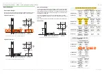
WALL
A
25
mm
(1.0
in.)
wide
smooth
surface
is
required
around
the
edge
of
the
wall
opening
to
enable
a
good
weather
seal.
Wall
Cavity
Any
cavity
in
the
wall
must
be
sealed
to
provide
a
flush
surface
that
does
not
extend
into
the
wall
opening.
Leave
the
gap
between
the
ATM
sleeve
and
the
wall
opening
clear
to
allow
air
at
room
temperature
to
circulate.
Installing
Through
a
Glass
Wall
If
you
are
installing
your
ATM
through
a
glass
wall
you
may
require
a
suitable
glass
support
(normally
a
steel
collar)
to
sit
between
the
ATM
collar
and
the
glass.
The
requirement
for
this
support
should
be
determined
by
the
architect.
If
required,
any
such
support
should
be
sourced
locally.
Collar
Tolerance
The
collar
has
a
tolerance
of
±
4mm
(0.2
in.
(
±
0.5°
))
at
the
top
and
bottom,
with
0
mm
(0.0
in.
(
0°
))
at
its
centre.
The
collar
cannot
accommodate
large
dips
or
depressions
in
the
wall.
Make
sure
the
wall
is
smooth
and
even.
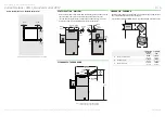
AMBIENT
LIGHTING
If
the
ATM
is
fitted
with
a
camera,
it
is
strongly
recommended
that
there
is
a
minimum
of
50
LUX
lighting
at
floor
level
within
the
area
illustrated
below.
TASK
LIGHTING
A
minimum
of
200
LUX
is
required
for
task
lighting.
0 mm
(0.0 in.)
±
4 mm
(0.16 in.)
±
4 mm
(0.16 in.)
1500 mm
(59.1 in.)
1000 mm
(39.4 in.)


