5-40 Chapter 5: Crisis Recovery
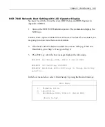
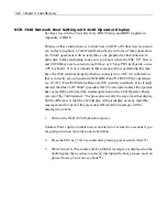
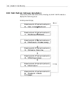
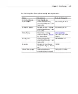
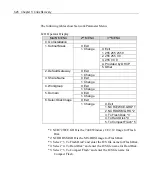
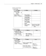
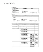
NCR 7448 Network Boot Setting with 2x20 Operator Display
See Keys Used in the Crisis Recovery, BIOS Setup, and BIOS Upgrade in
Appendix A: BIOS.
Purpose of these instructions is to show how an NCR or Partner Service person
can re-flash (re-ghost) a 7448 Flash Disk subsystem. Some of these operations
are "blind" operations with no lead-thru, so be prepared for that situation. In
particular, before attempting, make sure you know where the ESC, UP, Down,
and ENTER keys are located on your 80 key or 176 key POS keyboards, or use
a PC keyboard. It is very important that someone who is performing this task,
have the 7448 terminal properly ethernet connected to an NT 4.0 workstation
that is correctly set-up to perform NCR DHCP and NCR TFTP file operations
(i.e. G370-1724-0000 Platform Recovery SW correctly installed). It is strongly
advised that this 2x20 "blind" procedure NOT be attempted unless the operator
has successfully performed the similar operation on the LCD Operator Dislay
version of the 7448 terminal. The procedure is really the same for either display,
but the difference is that the 2x20 display will not display as many lead-thru
messages (and for part of this procedure NO lead-thru messages will be
displayed on 2x20).
1.
Turn on the NCR 7448 Workstation power.
Caution: Power up the workstations at an interval of at least five seconds if you
are going to turn on more than one workstation.
2.
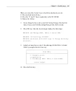
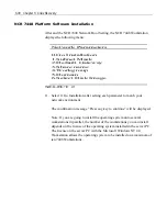
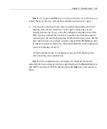
Press the ESC key 10-12 seconds after pressing power switch.(Note*1)
3.
Wait at least 20-25 seconds, and if no further messages are displayed on the
2x20 display, then you have correctly interupted the boot process, and can
proceed to step #4 (if not, see Note*1)
Содержание 7448 Workstation
Страница 1: ...NCR 7448 Workstation Release 1 4 Hardware User s Guide B005 0000 1202 Issue F...
Страница 6: ......
Страница 15: ...xiii...
Страница 16: ......
Страница 45: ...Chapter 2 Workstation Hardware Installation 2 7...
Страница 48: ...2 10 Chapter 2 Workstation Hardware Installation...
Страница 64: ...3 16 Chapter 3 Installing Optional Hardware Features 14 Connect the cable connectors...
Страница 65: ...Chapter 3 Installing Optional Hardware Features 3 17 15 Attach the Hard Disk on the AC bracket...
Страница 72: ...3 24 Chapter 3 Installing Optional Hardware Features...
Страница 122: ...4 50 Chapter 4 Setup How to Perform MSR Test...
Страница 152: ...4 80 Chapter 4 Setup...
Страница 158: ...5 6 Chapter 5 Crisis Recovery 3 Click Next 4 Click Install...
Страница 159: ...Chapter 5 Crisis Recovery 5 7 5 Setup exe will automatically install the software onto the server PC 6 Click Finish...
Страница 180: ...5 28 Chapter 5 Crisis Recovery 2 Double click Network and Dial up Connections 3 Double click Local Area Connection...
Страница 181: ...Chapter 5 Crisis Recovery 5 29 4 Click Properties 5 Select Internet Protocol TCP IP and click Properties...
Страница 202: ...5 50 Chapter 5 Crisis Recovery...
Страница 213: ...Appendix A BIOS A 11...
Страница 232: ......
Страница 239: ...Appendix B B 7 4 Click Next 5 Select a setup type Typical type Compact type or Custom Type and then click Next...


