135
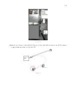
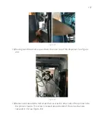
Figure 244
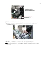
Figure 245
14)
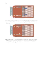
Once the heater is installed, the printer cables must be routed away from the
heater grille, as shown in the following steps.
15)
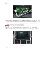
On the A-Side printer (the printer on the same side as heater and directly in front of
the wire guard (497-0522796), loosen the M4 screw holding the ground ring
terminal and printer chassis lid to the printer chassis. Retain screw for later use.
See location as described in. See Figure 246
Содержание 6003-K001-V002
Страница 2: ......
Страница 4: ......
Страница 18: ...4 RECOMMENDED MATERIALS N A...
Страница 36: ...22 Figure 33 Figure 34...
Страница 44: ...30 Figure 49...
Страница 67: ...53 Figure 92 47 Repeat steps 45 and 46 for the B side of the dispenser...
Страница 102: ...88 Figure 158 5 Replace Lower door using GCBO Lower Door Key See Figure 159 and Figure 160 Figure 159...
Страница 103: ...89 Figure 160...
Страница 110: ...96 Figure 173...
Страница 120: ...106 15 Use a 751 key to close the bottom printer door...
Страница 126: ...112 Figure 200 Figure 201 14 Position heater along bottom dispenser wall like shown See Figure 202 below Figure 202...
Страница 141: ...127 Figure 230 44 Repeat steps 32 43 for the opposite side of the dispenser...
Страница 162: ...148 Figure 270 41 Repeat steps 29 40 for the opposite side of the dispenser...
Страница 163: ...1 MERLIN REVISION B...

