Thrusters
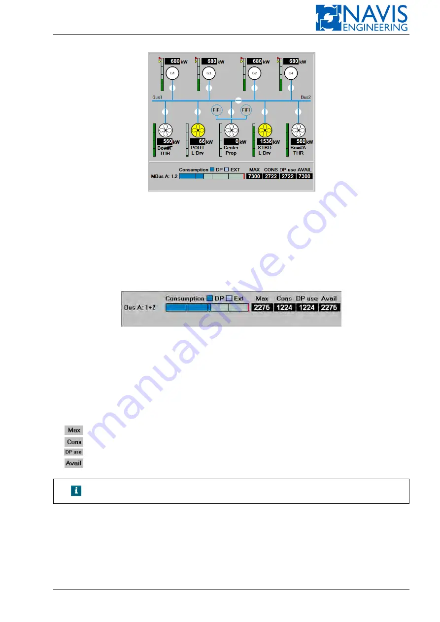
Figure 6.47: An example of power limites thrusters in the Power mimic diagram
6.4.4.3
Power consumption display
Power consumption display in the middle part of the Power View where the information about power consumption on
main buses and main engines is shown.
Note that the maximum available power and power available for DP are calculated for the generators connected to
the bus, and for the generator power limits which have been set in the PowerLimits parameter page. If the tie-breaker is
closed, the two buses are considered as one bus.
The name of one or several buses (depending on the tie breaker position) and main engines is indicated in the left part
as shown above. If the name of the bus (or buses) is red it means that Blackout prevention function is activated for the bus
(or buses), black – not activated.
Total power consumption is displayed as a percentage of the maximum available power on a bar graph:
– Dark blue bar shows the power used for DP operations;
– Light blue bar shows the power consumed by the external power consumers.
Numerical indicators show the power values for:
maximum available power
consumed power (by all the consumers)
power used for DP operations
power available for DP operations
NOTE!
Power units are set in the Measure units page of the Param window.
6.4.5
Indication of Blackout Prevention Function
When a generator is overloaded, the Generator power bar indicator becomes red-colored. It means that Blackout
Prevention Function is activated. The name of the bus to which a generator is connected becomes red-colored. The alarm
‘BusN Blackout Prevention: Gm’ is generated in the system, where N means a bus name, m is a number of the generator
overloaded. When a main engine is overloaded the alarm ‘Port (Stbd) Main Engine Overload Protection’ is generated in
the system. Main Engine power bar indicator becomes red-colored.
Doc. 000.JDP-10000-OME, rev.3.3.13/“2102.$–17A-Advanced”
124
Содержание NavDP 4000 Series
Страница 88: ...NAVIS NavDP 4000 Operation Manual Figure 5 35 Dark Theme 87 Doc 000 JDP 10000 OME rev 3 3 13 2102 17A Advanced...
Страница 222: ...NAVIS NavDP 4000 Operation Manual Figure 10 74 Drift Plot Window 221 Doc 000 JDP 10000 OME rev 3 3 13 2102 17A Advanced...
Страница 324: ...NAVIS NavDP 4000 Operation Manual Figure H 4 Remote DLS Mode 323 Doc 000 JDP 10000 OME rev 3 3 13 2102 17A Advanced...


