GV60 TROUBLESHOOTING MANUAL
RESPONDING TO ALARMS
PAGE 4.1.10
VERSION 1.0 2018-01-01
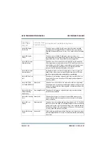
Table 4.1.1: Troubleshooting Alarms
Device and
Alarm Name
(AUI, UI)
Controller Front
Panel LED (color)
Description and Troubleshooting Action
Controller: AC
Summary (AC Summ)
-
Not displayed in AUI or UI status. Configurable as a remote output. This
alarms occurs if there are any ac input related alarms present. Check for
other specific ac fault alarms.
Controller: All PAs
Inactive
Power Amplifier (red) This alarm indicates that all of the transmitter’s power amplifiers are
inactive due to external conditions such as ac loss, removal of power supply
modules or RF power modules, or faults in the power supply modules or RF
power modules. If there are power supply module or RF power module
related alarms present, follow the associated troubleshooting procedure.
Controller: Audio Loss
Summary
Exciter (red)
Not displayed in AUI or UI status. Configurable as a remote output. This
alarms occurs if there are any audio loss alarms present. Check for specific
audio loss alarms and troubleshoot accordingly. Ensure the preset audio
settings agree with the audio being applied to the exciter.
Controller: Auto
Changeover Occurred
(Auto Changeover)
Exciter (amber)
This alarm occurs when the controller has initiated an exciter changeover to
the standby exciter, due to a possible fault with the main exciter.
Controller: Cabinet A
(or B) SWR Shutback
Output Network (red) This alarm occurs if the cabinet A (or B) - DC reflected power sample
exceeds the shutback threshold set on the associated rack 2 (or rack 6)
comparator circuit.
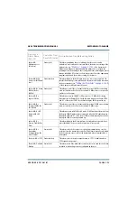
Controller:
Changeover in
Progress (In
Changeover)
Exciter (red)
This alarm occurs only while an exciter changeover is in progress. It will
clear once the changeover is complete.
Controller: Combiner
Match
Output Network (red) This alarm occurs if there is an excessive amount of power in the transmitter
combining stage that cannot be accounted for. This may be the result of a
fault in the combiner.
Controller: Config File
Not Found (Cfg File
Not Found)
Exciter (red)
This alarm occurs when the controller does not find a valid configuration file
to load at power-up. This alarm is unlikely, but may occur during
replacement of a controller module. It clears when the correct settings are
entered.
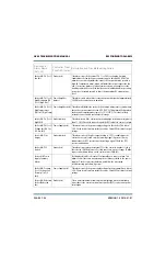
Controller: CPLD
Version Mismatch
(CPLD Ver Mismatch)
Exciter (red)
This alarm occurs when there is an incompatible software release in the
controller module’s CPLD. Update the software to clear the fault.
Controller: Current
Imbalance
Output Network (red) This alarm occurs if the Combiner Match alarm occurs due to a PA current
imbalance in the RF power modules
Содержание GV60
Страница 2: ......
Страница 4: ......
Страница 8: ...GV60 TROUBLESHOOTING MANUAL PAGE 4 VIII VERSION 1 0 2018 01 01 ...
Страница 102: ...GV60 TROUBLESHOOTING MANUAL PARTS LISTS PAGE 4 2 12 VERSION 1 0 2018 01 01 ...
Страница 463: ...VERSION 1 0 2018 01 01 MD 17 Figure MD 17 NAPA31C Power Amplifier PWB Q1 ...
Страница 466: ...VERSION 1 0 2018 01 01 MD 20 Figure MD 20 NAI23A RF Drive Splitter Changeover Assembly FRONT BACK ...
Страница 473: ...VERSION 1 0 2018 01 01 MD 27 Figure MD 27 NAL17 4 Input Reject Load Assembly TOP VIEW END VIEW 2 INPUT REJECT PWB A1 ...
Страница 475: ...GV60 TROUBLESHOOTING MANUAL LIST OF TERMS PAGE 4 6 2 VERSION 1 0 2018 01 01 ...
Страница 476: ......


