


Chapter 4
Theory of Operation
4-2
ni.com
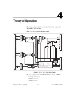
•
Digital control circuitry
•
Analog circuitry
The SCXI-1102/B/C modules consist of 32 multiplexed input channels,
each with a software-programmable gain of 1 or 100. Each input channel
has its own lowpass filter. The SCXI-1102/B/C modules also have a digital
section for automatic control of channel scanning, temperature sensor
selection, and gain selection.
Rear Signal Connector, SCXIbus Connector, and
SCXIbus Interface
The SCXIbus controls the SCXI-1102/B/C module. The SCXIbus interface
connects the rear signal connector to the SCXIbus, allowing a DAQ device
to control the SCXI-1102/B/C module and the rest of the chassis.
Digital Control Circuitry
The digital control circuitry consists of the Address Handler and registers
that are necessary for identifying the module, starting calibration
information, setting the gain, and selecting the appropriate channel.
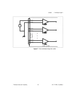
Analog Circuitry
The analog circuitry per channel consists of a lowpass filter and an
amplifier with a software selectable gain of 1 or 100. The CJ SENSOR
channel also has a buffered lowpass filter but has no amplifier. The
channels and CJ SENSOR are multiplexed to a single output buffer.
Analog Input Channels
Each of the 32 analog input channels feeds to a separate amplifier with a
programmable gain of 1 or 100. Then the signal passes through a fixed
lowpass filter.
Note
Because of the 2 Hz bandwidth of the SCXI-1102 module input channels, after
changing the gains you must wait approximately 3 s for the channels settle in order to get
an accurate measurement. NI-DAQ automatically accounts for this time and determines
when the module output has settled. For the SCXI-1102B and SCXI-1102C modules, this
time is approximately 100 ms and 1 ms, respectively.


