background image

SCXI-1383 Power Supply/Float Charger

8

ni.com

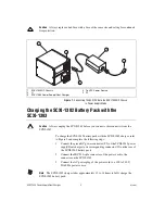
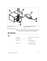
Figure 3.  

Connecting the SCXI-1383 Power Supply/Float Charger to the SCXI-1000DC 

Chassis and the SCXI-1382 Battery Pack in the Float-Charging Mode

Specifications

Input

Input voltage ...........................................100 to 240 VAC (universal input)

Input frequency.......................................50/60 Hz

Input current ...........................................2 A at 115 VAC or 

1 A at 230 VAC (max)

Inrush current..........................................<30 A at 115 VAC or 

60 A at 230 VAC input

1

SCXI-1000DC Chassis

2

J1

3

J2

4

SCXI-1382 Battery Pack

5

SCXI-1383 Power Supply/Float Charger

6

To VAC Power Source

7

P2

8

P1

1

4

2

3

5

6

7

Содержание SCXI-1383

Страница 1: ...2 battery pack float charging the SCXI 1382 battery pack while powering the SCXI 1000DC chassis which provides uninterruptable power for the SCXI 1000DC chassis Each of these tasks are detailed in this document Conventions The following conventions are used in this guide The symbol leads you through nested menu items and dialog box options to a final action The sequence File Page Setup Options dir...

Страница 2: ... filenames and extensions and code excerpts What You Need to Get Started To set up and use the SCXI 1383 you need the following SCXI 1383 power supply float charger SCXI 1383 Power Supply Float Charger Installation Guide Read Me First Safety and Radio Frequency Interference One of the following power cords depending on the power requirements of your geographical region United States Japan power co...

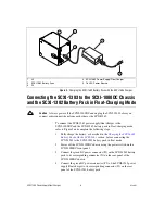
Страница 3: ...to its corresponding connector J1 on the rear panel of the SCXI 1000DC chassis 3 Connect the IEC 320 style connector of the power cord to its connector on the power supply float charger 4 Connect the AC power plug of the power cord to a 100 to 240 VAC 50 60 Hz power source 5 Power on the SCXI 1000DC chassis using the power switch on the chassis front panel The green LED on top of the SCXI 1383 whe...

Страница 4: ...h the SCXI 1383 charger refer to Figure 2 and complete the following steps 1 Connect the green DC power connector P2 of the SCXI 1383 power supply float charger to its corresponding connector J2 on the rear of the SCXI 1382 battery pack 2 Connect the IEC 320 style connector of the power cord to the connector on the SCXI 1383 3 Connect the AC power plug of the power cord to a 100 to 240 V 50 60 Hz ...

Страница 5: ...ged state Do not puncture disassemble mutilate or incinerate the battery pack Recycle the battery or dispose of the battery pack with automotive battery scrap The battery charger dissipates heat Use the charger in an area with ample air circulation The green LED on top of the SCXI 1383 when used to charge the SCXI 1382 has the following characteristics the green LED is off which could mean the SCX...

Страница 6: ...he following steps 1 Fully charge the battery as described in the Charging the SCXI 1382 Battery Pack with the SCXI 1383 section before connecting the SCXI 1383 to the SCXI 1382 battery pack in float mode 2 Power off the SCXI 1000DC chassis using the power switch on the SCXI 1000DC front panel 3 Connect the green DC power connector P1 on the SCXI 1382 battery pack to its corresponding connector J1...

Страница 7: ...tes only if the battery is not fully charged The green LED on top of the SCXI 1383 when used to float charge the SCXI 1382 has the following characteristics the green LED is off which could mean the SCXI 1382 battery pack is fully charged there is no VAC power to the SCXI 1383 the SCXI 1383 output is disconnected the SCXI 1382 fuse is bad the green LED is bright the SCXI 1382 is charging the green...

Страница 8: ...he Float Charging Mode Specifications Input Input voltage 100 to 240 VAC universal input Input frequency 50 60 Hz Input current 2 A at 115 VAC or 1 A at 230 VAC max Inrush current 30 A at 115 VAC or 60 A at 230 VAC input 1 SCXI 1000DC Chassis 2 J1 3 J2 4 SCXI 1382 Battery Pack 5 SCXI 1383 Power Supply Float Charger 6 To VAC Power Source 7 P2 8 P1 1 4 2 3 5 6 7 ...

Страница 9: ...output Protections 2 A 250 V ceramic input fuse reverse polarity protection performed by auto recovery circuit the unit protects itself in case of short circuit or if the battery voltage is below 5 to 7 V Physical Dimensions 16 5 by 8 0 by 5 7 cm 6 5 by 3 2 by 2 2 in Connectors AC inlet IEC 320 CEE 22 standard DC output Phoenix Contact Combicon connector with UL 1015 16 AWG CSA TEW 105 C 600 V wir...

Страница 10: ...standards of safety for electrical equipment for measurement control and laboratory use IEC 61010 1 EN 61010 1 UL 3111 1 UL 61010B 1 CAN CSA C22 2 No 1010 1 Note For UL and other safety certifications refer to the product label or to ni com Electromagnetic Compatibility Emissions EN 55011 Class A at 10 meters FCC Part 15A above 1 GHz Immunity EN 61326 1997 A2 2001 Table 1 EMC EMI CE C Tick and FCC...

Страница 11: ...irectives as amended for CE marking as follows Low Voltage Directive safety 73 23 EEC Electromagnetic 89 336 EEC Compatibility Directive EMC Note Refer to the Declaration of Conformity DoC for this product for any additional regulatory compliance information To obtain the DoC for this product click Declarations of Conformity Information at ni com hardref nsf ...

Отзывы: