


Chapter 2
Configuration and Installation
©
National Instruments Corporation
2-21
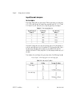
Figure 2-6.
Floating AC-Coupled Signal Connection
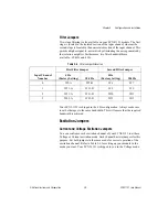
Figure 2-7.
AC-Coupled Signal Connection with High Common-Mode Voltage
For AC-coupled signals, you should connect an external resistor from the
positive input channel to the signal reference. This is needed to provide the
DC path for the positive input bias current. Typical resistor values range
from 100 k
Ω
to 1 M
Ω
. This solution, although necessary in this case, lowers
the input impedance of the input channel amplifier and introduces an
additional offset voltage proportional to the input bias current and to the
resistor value used. The typical input bias current of the amplifier consists
of ±80 pA and a negligible offset drift current. When a 100 k
Ω
resistor is
used, this will result into ±8 µV of offset, which is insignificant in most
applications. However, if larger resistors are used, significant input offset
may result. To determine the maximum offset introduced by the biasing
resistor, use the following equation:
The input signal range of an SCXI-1121 input channel is ±5 V/ G
total
referenced to its negative input, where G
total
is equal to the product of the
first-stage and second-stage gains. In addition, the input channels are
overvoltage protected to 250 V
rms
with power on or off at a maximum of
4.5 m
Arms
sink or source.
V
s
V
out
+
–
+
–
R
bias
+
Module
V
s
V
out
+
–
+
–
R
bias
V
cm
High
CMV
+
–
+
Module
V
ofsbias
I
bias
R
bias
×
=


