
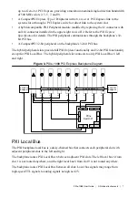

Initialization software uses the configuration information specific to each adjacent peripheral
module to evaluate local bus compatibility.
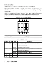
PXI Trigger Bus
All slots on the same PXI bus segment share eight PXI trigger lines. You can use these trigger
lines in a variety of ways. For example, you can use triggers to synchronize the operation of
several different PXI peripheral modules. Modules can pass triggers to one another on the
lines, allowing precisely timed responses to asynchronous external events the system is
monitoring or controlling.
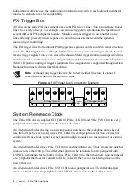
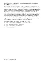
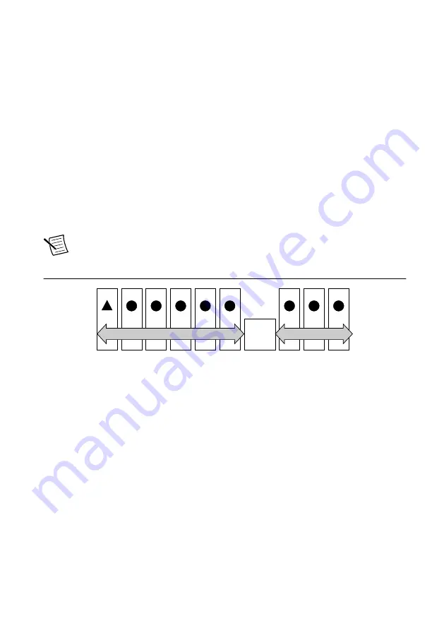
The PXI trigger lines from adjacent PXI trigger bus segments can be routed in either direction
across the PXI trigger bridges through buffers. This allows you to send trigger signals to, and
receive trigger signals from, every slot in the chassis. Static trigger routing (user-specified line
and directional assignments) can be configured through Measurement & Automation Explorer
(MAX). Dynamic routing of triggers (automatic line assignments) is supported through certain
National Instruments drivers like NI-DAQmx.
Note
Although any trigger line may be routed in either direction, it cannot be
routed in more than one direction at a time.
Figure 4. PXI Trigger Bus Connectivity Diagram
H
H
H
7
8
9
H
H
H
H
1
2
3
4
5
6
PXI
Trigger
Bridge #1
PXI Trigger Bus #1
PXI Trigger Bus #2
H
System Reference Clock
The PXIe-1088 chassis supplies PXI_CLK10, PXIe_CLK100 and PXIe_SYNC100 to every
peripheral slot with an independent driver for each signal.
An independent buffer (having a source impedance matched to the backplane and a skew of
less than 250 ps between slots) drives PXI_CLK10 to each peripheral slot. You can use this
common reference clock signal to synchronize multiple modules in a measurement or control
system.
An independent buffer drives PXIe_CLK100 to each peripheral slot. These clocks are matched
in skew to less than 100 ps. The differential pair must be terminated on the peripheral with
LVPECL termination for the buffer to drive PXIe_CLK100 so that when there is no peripheral
or a peripheral that does not connect to PXIe_CLK100, there is no clock being driven on the
pair to that slot.
An independent buffer drives PXIe_SYNC100 to each peripheral slot. The differential pair
must be terminated on the peripheral with LVPECL termination for the buffer to drive
8
|
ni.com
|
PXIe-1088 User Guide