background image

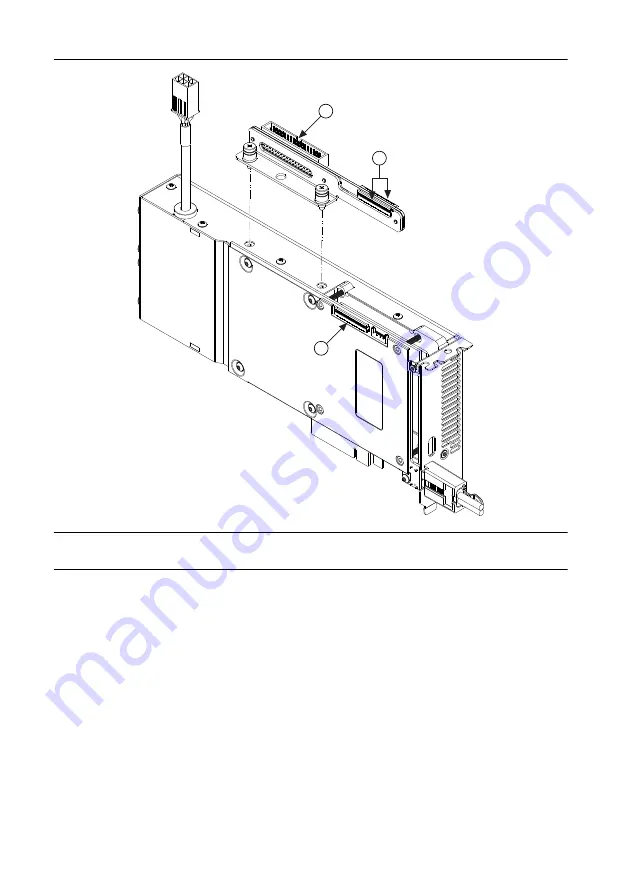
Figure 6. Synchronization Connectors on the PCIe-5785

1

1

2

1. Compact synchronization interface cable connector
2. Compact synchronization interface cable to RTSI adapter

Sharing Signals and Triggers with Another PCI
Express FlexRIO Device

1.

Install the PCIe-5785 and another PCI Express FlexRIO device in one PCI Express
backplane.

2.

Insert one end of the compact synchronization interface cable into the synchronization
connector on each PCI Express FlexRIO device. Ensure the contacts on the cable are
facing the FlexRIO device.

Sharing Signals and Triggers with PCI Express
Devices Using RTSI

1.

Mount the RTSI adapter on the top of the PCIe-5785 using the attached mounting screws.

2.

Install the PCIe-5785 and up to five additional PCI Express devices in one PCI Express
backplane.

PCIe-5785 Getting Started Guide

  | 

© National Instruments

  | 

13

Содержание PCIe-5785

Страница 1: ...cking the Kit 3 PCIe 5785 Kit Contents 3 Preparing the Environment 3 Installing the Application Software and Driver 4 Installing the PCIe 5785 4 PCIe 5785 Front Panel 5 Configuring the PCIe 5785 in MAX 7 FlexRIO Examples 8 Accessing FlexRIO Examples 8 Block Diagram 8 Component Level Intellectual Property CLIP 11 Making a Measurement with LabVIEW 12 Synchronization 12 Sharing Signals and Triggers w...

Страница 2: ...about the FPGA module front panel connectors and I O programming instructions and I O component level IP CLIP LabVIEW Examples Available in NI Example Finder In LabVIEW click Help Find Examples Hardware Input and Output FlexRIO Contains examples of how to run FPGA VIs and Host VIs on your device IPNet Located at ni com ipnet Contains LabVIEW FPGA functions and intellectual property to share FlexRI...

Страница 3: ...c package when the device is not in use PCIe 5785 Kit Contents The following items are included in the device kit The PCIe 5785 The FlexRIO Support driver software media Documentation Maintain Forced Air Cooling Note to Users PCIe 5785 Getting Started Guide this document Preparing the Environment Ensure the environment in which you are using the PCIe 5785 meets the following specifications Operati...

Страница 4: ...ng started with the LabVIEW FPGA Module Documentation for the LabVIEW FPGA Module is available at ni com manuals and by selecting Start All Programs National Instruments LabVIEW LabVIEW Manuals 3 Optional Install the LabVIEW Real Time Module Refer to the LabVIEW Real Time Module Release and Upgrade Notes for system requirements installation instructions and additional information about using the L...

Страница 5: ...ing the bracket screws increases mechanical stability and electrically connects the front panel to the chassis which can improve the signal quality and electromagnetic performance 7 Connect the 6 pin PCI Express power connector from the power supply to the PCIe 5785 8 Replace any access panels on the computer case 9 Power on your computer PCIe 5785 Front Panel The following figure shows the PCIe 5...

Страница 6: ...Figure 2 PCIe 5785 Front Panel PCIe 5785 AI0 DIO 4Vpp MAX AI1 AO0 AO1 REF CLK IN 4Vpp MAX The following table describes the signal connections for the PCIe 5785 6 ni com PCIe 5785 Getting Started Guide ...

Страница 7: ...al 5 0 V DC Output GND Ground Notice The maximum input signal levels are valid only when the module is powered on To avoid permanent damage to the PCIe 5785 do not apply a signal to the device when the module is powered down Notice Connections that exceed any of the maximum ratings of any connector on the PCIe 5785 can damage the device and the chassis NI is not liable for any damage resulting fro...

Страница 8: ...Examples FlexRIO examples are available in LabVIEW s NI Example Finder Complete the following steps to access the examples by task 1 In LabVIEW click Help Find Examples 2 In the NI Example Finder window that appears click Hardware Input and Output FlexRIO The examples are sorted by task Click on an example and refer to the Information window for a description of the example Refer the Requirements ...

Страница 9: ...r Supplies Flash FPGA Triggers Clk 100 Gen3 x8 PCIe 12 V 3 3 V 12 V Clk 10 Module Clocking Synchronization PLL DRAM Bank 0 2 GB DRAM Bank 1 2 GB Synchronization Connector PCIe Connectors The following figure shows a block diagram of the carrier portion of the PCIe 5785 KU040 and KU060 FPGA versions PCIe 5785 Getting Started Guide National Instruments 9 ...

Страница 10: ... MGTs Reference Clock Power Supplies Flash FPGA Triggers Clk 100 Gen3 x8 PCIe 12 V 3 3 V 12 V Clk 10 Module Clocking Synchronization PLL DRAM Bank 0 2 GB DRAM Bank 1 2 GB Synchronization Connector PCIe Connectors MGTs The following figure shows a block diagram of the I O portion of the PCIe 5785 10 ni com PCIe 5785 Getting Started Guide ...

Страница 11: ...lectual property CLIP for HDL IP integration FlexRIO devices support two types of CLIP user defined and socketed User defined CLIP allows you to insert HDL IP into an FPGA target enabling VHDL code to communicate directly with an FPGA VI Socketed CLIP provides the same IP integration of the user defined CLIP but it also allows the CLIP to communicate directly with circuitry external to the FPGA Ad...

Страница 12: ...he VI Synchronization You can use the compact synchronization interface cable part number 769693 01 to share a Reference Clock and triggers between the PCIe 5785 and another PCI Express FlexRIO device You also can use the compact synchronization interface to RTSI adapter part number 147008A 01L to synchronize the PCIe 5785 with a PCI Express device that supports synchronization using RTSI 12 ni co...

Страница 13: ...ess backplane 2 Insert one end of the compact synchronization interface cable into the synchronization connector on each PCI Express FlexRIO device Ensure the contacts on the cable are facing the FlexRIO device Sharing Signals and Triggers with PCI Express Devices Using RTSI 1 Mount the RTSI adapter on the top of the PCIe 5785 using the attached mounting screws 2 Install the PCIe 5785 and up to fi...

Страница 14: ...uration tree expand Devices and Interfaces 2 If the module is still not listed power off the system ensure that all hardware is correctly installed and restart the system 3 Navigate to the Device Manager Operating System Description Windows 10 8 1 Right click the Start button and select Device Manager Windows 7 Select Start Control Panel Device Manager 4 Verify the PCIe 5785 appears in the Device ...

Страница 15: ...m NI Application Engineers Visit ni com services for information about the services NI offers Visit ni com register to register your NI product Product registration facilitates technical support and ensures that you receive important information updates from NI NI corporate headquarters is located at 11500 North Mopac Expressway Austin Texas 78759 3504 NI also has offices located around the world ...

Страница 16: ...ments EULAs and third party legal notices in the readme file for your NI product Refer to the Export Compliance Information at ni com legal export compliance for the NI global trade compliance policy and how to obtain relevant HTS codes ECCNs and other import export data NI MAKES NO EXPRESS OR IMPLIED WARRANTIES AS TO THE ACCURACY OF THE INFORMATION CONTAINED HEREIN AND SHALL NOT BE LIABLE FOR ANY...

Отзывы: