manualshive.com logo in svg
background image

STATUS LED

The STATUS LED is off during normal operation. After the device powers on, the cRIO-9024
indicates specific error conditions by flashing the STATUS LED a certain number of times
every few seconds. If you observe this behavior after the device powers on, contact National
Instruments support.
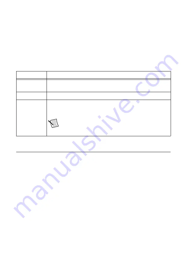
USER1 LED

The USER1 LED can display the indications described in the following table:

Table 3.

 USER1 LED Indications

Indication

Description


Flashing rapidly Indicates an error condition. Open Systems Manager to the 

Dashboard

page to see the device status.

Flashing steadily Indicates normal operation.

Solid

Indicates that USB operations are in progress, such as reading or writing
the connection information file. You can safely remove the USB drive
when this LED resumes blinking steadily.

Note


This device polls USB drives every 15 seconds, so you

might need to wait up to 15 seconds after a USB operation
begins for the LED to light.

Troubleshooting Network Communication

If the CMS-9024 does not connect to NI InsightCM Server with a status of Online, try the
following troubleshooting tips:

Check the Ethernet cable connections on the CMS-9024, host computer, and router.

If you have network firewalls or other security software enabled, try temporarily turning
them off. You might also need to add an exception for NI InsightCM Server by
completing the following steps:
1.

Navigate to the standard Microsoft Windows Control Panel utility for managing
firewall settings.

2.

Click 

Allow a program or feature through Windows Firewall

.

3.

Click 

Allow another program

.

4.

Select 

NI InsightCM

 and click 

Add

.

5.

Click 

OK

 and close the firewall settings.

Ensure that the ports listed in the following table are open to communication on the host
computer. If you are using an intelligent switch on the network, ensure that the switch is
not disabling these ports.

Maintaining NI CMS-9024 Hardware for an NI InsightCM System

  | 

© National Instruments

  | 

13

Содержание CMS-9024

Страница 1: ...assis 3 Precautions to Take before Mounting the Chassis 4 Measuring the Ambient Temperature of the Chassis 4 Accommodating Air Circulation and Cabling Clearance 4 Mounting the Chassis Directly on a Fl...

Страница 2: ...ed system Figure 1 CompactRIO Reconfigurable Embedded System 1 2 3 1 cRIO 9024 intelligent real time embedded controller 2 cRIO 9114 eight slot reconfigurable embedded chassis 3 C Series I O module Co...

Страница 3: ...t port 1 9 RJ 45 Ethernet port 2 Note NI Condition Monitoring Systems do not use the DIP switches Leave these switches in the OFF position Mounting the Chassis To obtain the maximum allowable ambient...

Страница 4: ...What do I need to know about mounting the chassis in environments with high shock and vibration Visit ni com info and enter the Info Code criomounting Precautions to Take before Mounting the Chassis...

Страница 5: ...for cabling clearance for common connectors such as the 10 terminal detachable screw terminal connector as shown in the following figure Figure 4 cRIO 9114 Cabling Clearance Requirements 274 0 mm 10...

Страница 6: ...for environments with high shock and vibration 1 Use the dimensions provided in this document to prepare the surface for mounting the chassis 2 Align the chassis on the surface 3 Fasten the chassis t...

Страница 7: ...contain any I O modules before you remove it Mounting the Chassis on a DIN Rail Complete the following steps to use the NI 9915 DIN rail mounting kit part number 779018 01 to mount the chassis on a s...

Страница 8: ...adapter bracket and screws with the desktop mounting kit Refer to the NI 9901 documentation for more information about mounting the chassis on a desktop Installing C Series I O Modules in the Chassis...

Страница 9: ...alled on the CMS 9024 You must fill module slots in ascending order starting with slot 1 You cannot skip any slots but you do not have to use every slot Note You must connect tachometers to the module...

Страница 10: ...Attach the ring lug to the grounding terminal 4 Tighten the grounding screw to 0 5 N m 4 4 lb in of torque 5 Attach the other end of the wire to the grounding electrode system of your facility using...

Страница 11: ...the terminal screw 3 Connect the negative lead of the power supply to one of the C terminals of the power connector and tighten the terminal screw 4 Optionally connect the positive lead of another pow...

Страница 12: ...er connector while the power connector is plugged in to the controller or while the power supply is on Powering On the Controller When you apply power to the CompactRIO system the controller runs a po...

Страница 13: ...it up to 15 seconds after a USB operation begins for the LED to light Troubleshooting Network Communication If the CMS 9024 does not connect to NI InsightCM Server with a status of Online try the foll...

Страница 14: ...ains network and connection properties Tip You can use the blank USB drive included in the NI InsightCM Server kit 2 Remove the USB drive from the controller when the USER1 LED returns to blinking ste...

Страница 15: ...ess documentation for C Series modules that are compatible with NI InsightCM Worldwide Support and Services The National Instruments website is your complete resource for technical support At ni com s...

Страница 16: ...and third party legal notices in the readme file for your NI product Refer to the Export Compliance Information at ni com legal export compliance for the National Instruments global trade compliance p...

Отзывы: