Configuration and Installation
Chapter 2
SCXI-1100 User Manual
2-16
© National Instruments Corporation
signals in which both the positive and negative channel inputs are in the
±
10 V range. Thus the
common-mode input range for the SCXI-1100 depends on the size of the differential input signal:
V
diff
= V+
in
- V-
in
The exact formula for the permissible common-mode input range is as follows:
V
c
=
±
( 10 V - G
1
( V+
in
- V-
in
)/2)
Thus, with a differential voltage of 10 V and a first-stage gain of G
1
= 1, the maximum possible
common-mode voltage would be
±
5 V. You measure the actual common-mode voltage available
at the PGIA input with respect to the SCXI-1100 ground. You can calculate the actual
common-mode voltage with the following formula:
V
cm-actual
= (V+
in
+ V-
in
)/2
where V+
in
is the signal at the positive input channel (CH#+) and V-
in
is the signal at the
negative input channel (CH#-). Both V+
in
and V-
in
are measured with respect to the SCXI-1100
chassis ground.
The analog input channels are overvoltage protected to
±
25 VDC with power on and to
±
15 VDC
with power off at a maximum of 20 mA sink or source.
Warning: Exceeding the differential and common-mode input ranges results in distorted input
signals. Exceeding the maximum input voltage rating between any two terminals
can damage the SCXI-1100, the SCXIbus backplane, and the data acquisition board.
National Instruments is not liable for any damages resulting from such signal
connections.
Thermocouple Connections
One of the main applications of the SCXI-1100 is thermocouple measurements. This section
describes the different type of thermocouple connections.
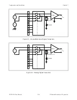
Your thermocouple can be either floating or ground referenced. When you connect your
thermocouple, make sure you know whether the thermocouple is floating or ground referenced.
If you are using a floating thermocouple, you must ground the PGIA CH- in one of the following
two ways:
•
Connect a wire on the terminal block from the CH- of interest to the chassis ground screw
terminal. If you are using several similar thermocouples, you can daisy chain the CH- of
interest to the chassis ground screw terminal. Use this method to avoid grounding all the
SCXI-1100 CH- and to create a solid ground connection; this is the recommended method of
referencing floating thermocouples.
•
Internally connect jumper W1 to the floating source position. This will connect all
SCXI-1100 CH- inputs to ground via a 100 k
Ω
resistor. However, this setting usually
increases settling time and common-mode noise.
If you are using a grounded thermocouple, do not ground the SCXI-1100 CH- and do not use
jumper W1 to ground floating signals because you will create a ground loop and adversely affect
the accuracy of your measurement.

