Configuration and Installation
Chapter 2
SCXI-1100 User Manual
2-6
© National Instruments Corporation
Grounding, Shielding, and Output Mode Selection
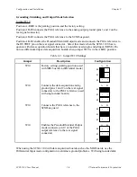
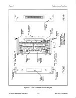
Jumper W10
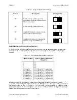
Position A-R0R1 is the parking position and the factory setting.
Position AB-R0 connects the PGIA reference to the analog output ground (pins 1 and 2 on the
rear signal connector).
Position AB-R1 connects the PGIA reference to the SCXIbus guard.
Position AB-R2 enables the Pseudodifferential Output mode and connects the PGIA reference to
the OUTREF pin on the rear signal connector. Select this mode when the SCXI-1100 has to
operate with data acquisition boards that have a nonreferenced single-ended input (NRSE). Do
not use differential input data acquisition boards when jumper W10 is in the AB-R2 position.
Table 2-2. Jumper W10 Settings
Jumper
Description
Configuration
W10
Factory setting; parking position (used
with MIO boards in differential mode)
R
0
R
1
R
2
•
•
•
•
•
•
A B
W10
Connects the data acquisition analog
ground (pins 1 and 2 on the rear signal
connector) to the PGIA reference (used
with single-ended boards)
R
0
R
1
R
2
•
•
•
•
•
•
A B
W10
Connects the PGIA reference to the
SCXIbus guard
R
0
R
1
R
2
•
•
•
•
•
•
A B
W10
Enables the Pseudodifferential Output
mode (connects pin 19 of the PGIA
output reference to the rear signal
connector)
R
0
R
1
R
2
•
•
•
•
•
•
A B
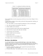
When using the SCXI-1100 with data acquisition boards such as the MIO boards, use the
Differential Input mode configuration to eliminate ground problems. With single-ended data

