

PIR1710 PASSIVE INFRARED SENSOR
•
INSTALLATION INSTRUCTIONS
SPECIFICATIONS
Coverage (l x w): 70’ x 60’ (21.3m x 18.3m) at 20°C
(68°F), typical.
Operating Temperature: –10° to + 50°C (14° to 122°F)
Mounting: Wall or corner, 12’ (3.6m) max.
Output: Normally-Closed Form-A Relay
Relay Time: Approximately 3 seconds
Contact Ratings
Alarm Relay: 100mA, 24Vdc with internal 10
Ω
current-
limiting resistor
Power-Supply Requirements
Note: This unit is intended for operation from a power
source that provides a 4 hour battery backup in the event
of a power failure.
Filtered Dc: 10.6 to 16Vdc nominal with battery backup
from control panel.
Current Drain: 23mA (idle or alarm) at 12Vdc (nominal)
Physical
Dimensions: 3.3” x 2.5” x 1.9” (8.4cm x 6.4cm x 4.8cm)
(HxWxD)
Shipping Weight: 5oz (142gm)
FEATURES
•
Lookdown zone provides coverage directly beneath sensor
•
Selectable Fixed (2 Pulse Bipolar) or Signal-Selective Process-
ing
TM
(SSP) Detection for optimum immunity to false alarms
•
Unique circuit design protects against false alarms due to radio-
frequency interference
•
Vertical and horizontal aiming capabilities
•
Dual-element sensor
•
Large lens area assures high sensitivity
•
Small size with ample wiring space
•
Power filtering provides protection against transients
•
Corner mountable
STANDARD LENS
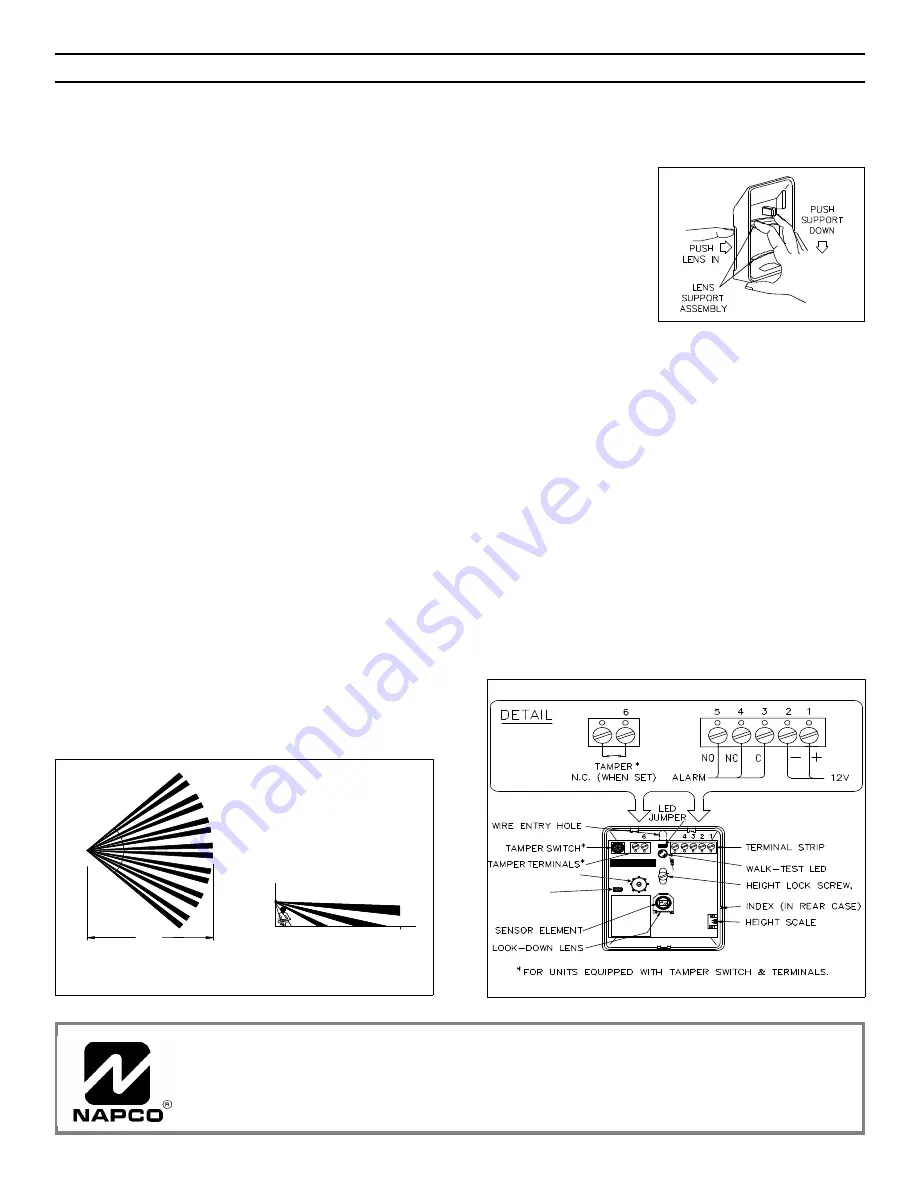
REPLACING THE LENS
The lens is mounted on a Lens Support insert that fits
inside the front cover. To install one of the accessory
lenses, proceed as follows.
1. While pushing the
lens in at the top, with fin-
gers straddling the LED
jewel, press down at the
top of the Lens Support
as shown until the sup-
port clears the three top
retainers. Be careful not
to d islo d g e the lo o k-
down-lens window.
2. Push the Lens Support up until it clears the three
bottom retainers and remove the assembly.
3. Straighten the lens tabs and slide out the lens.
4. Install the replacement lens: slide the tabs into the slots
in the Lens Support, then bend the tabs inward.
5. Install the assembly into the front cover (be sure lens
is right side up, as it will fit either way): slip the Lens Support
behind the lower retainers, then push in at the top until the
Lens Support snaps into place.
MOUNTING & WIRING
Allow at least three minutes for the unit to settle. The LED
will not function until the unit is ready. Do not point the unit
at sources of heat, such as radiators, space heaters, etc.
Adjust beams laterally by sliding the Lens Support horizon-
tally within its retainers. Loosen the Height Lock Screw and
set the board’s height scale to the mounted height of the
unit. Retighten the screw. To block a problem zone, apply
a piece of lens foil (supplied) to the
inside
segment of the
lens representing that zone. To extinguish the LED after
walk-testing, place a jumper in the LED Jumper position.
(a) TOP VIEW
(b) SIDE VIEW
85
o
6’
70’
70’
LOOKDOWN
ZONE
Standard Lens coverage pattern.
7
5
7
RANGE POT
SSP JUMPER:
ON=FIXED, OFF=SSP
PIR1710 mounting and wiring.
Napco Security Systems, Inc.
333 Bayview Avenue, Amityville, New York 11701
Sales, Repairs and Technical Service (Toll Free): (800) 645-9445
Technical Service Direct Line (Toll Free): (800) 645-9440
WI882A 8/97