NAPCO Gemini C-Series Control Panel Installation Instructions--Volume 2
Installation Instructions, Volume 2 Page 15
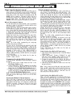
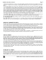
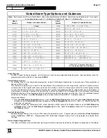
CONTROL PANEL OUTPUTS
*24V Regulated when the GEMC-24VR is installed.
DESCRIPTION OF SYSTEM OUTPUTS
The Gemini C-Series control panel motherboards have the ability to provide up to seven (7) integral programma-
ble outputs, four (4) optional Burglary outputs requiring the GEMC-BM or GEMC-BM/PS, and 88 additional exter-
nal outputs requiring external modules and devices.
These outputs are either
Fire outputs
or
Burglary outputs
as follows:
•
Fire outputs
are available on the motherboard (GEMC-XXXMB), motherboard Fire Bus modules (GEMC-
OUT8, GEMC-RM3008 and/or GEMC-NACXX) or the Fire SLC modules (GEMC-FW-SLC).
•
Burglary outputs
are available on the Burglary modules (GEMC-BM or GEMC-BM/PS), Burglary Module Burg
Bus modules (GEMC-OUT8 or GEMC-RM3008) or the Burglary SLC modules (GEMC-BSLC). For more infor-
mation regarding the Burglary outputs, see the GEMC-BSLC Burg SLC module installation instructions,
WI1648.
MOTHERBOARD INTEGRAL FIRE OUTPUTS
The motherboard has seven (7) integral programmable outputs:
•
Three 24V NAC outputs;
•
One NAC output selectable for 24V* or 12V regulated output;
Note:
The GEMC-96MB and GEMC-32MB only provide two 2A NAC circuits (one 24V and one 12V or 24V
selectable).
•
One unsupervised Form-C relay output selectable for 12V regulated or dry contacts; also suitable as a trouble
output;
•
Two active-low unsupervised 2A outputs (requires power-limited connection from panel
AUX PWR
output or
other listed power supply with maximum voltage of 28VDC).
In addition, the motherboard also has a dedicated unsupervised
TBL
(trouble) sounder output that activates
when there is a keypad 1 supervision failure.
88 ADDITIONAL EXTERNAL OUTPUTS
The system supports up to 88 additional external outputs, enabled in 11 "groups" of eight and enabled only on
the addressed device. Each group of eight is distinctly addressed as group "1" through group "11", and only one
group of the same address may be placed on the system. Additionally, the groups do
NOT
have to be contigu-
ous (output groups can skip addresses, if desired).
Of the 88 external outputs, only the first 40 external outputs (the first 5 groups) are capable of being supervised
outputs; the remaining 48 external outputs (outputs 41-88) are unsupervised outputs.
Note:
Only these first 40
external outputs are able to have a description appear on the 28 character GEMC-FK1 Fire keypad LCD display.
Note:
The integral outputs and first 8 outputs of the 88 external outputs can be "Event Driven" outputs or pro-
grammed "By Zone" to activate on alarm. Note that in this manual, all External Outputs may be either NAC's,
SOM's, relays or active low outputs.
GEMC-OUT8 & GEMC-RM3008 MODULES
Of the first 40 external Fire outputs, the GEMC-OUT8 output module provides one group of eight unsupervised
active low outputs, and the GEMC-RM3008 relay module provides one group of eight unsupervised Form C dry
relay contact outputs. These outputs can be used for controlling bells, door latches, lights and other similar de-
vices.
With the GEMC-RM3008 and the GEMC-OUT8, the panel controls the closure of each relay or output. The panel
identifies the relay or output by the proper placement of 4 address jumpers located on the module PC board. For
example, when relay number 1 is activated, relay #1 of GEMC-RM3008 module #1 activates if it is on the system.
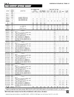
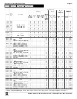
If output number 88 is activated, the 8th output of the GEMC-OUT8 module #11 is activated. See the
FIRE OUT-
PUT RELAY CHART
further in this manual. For more information, see WI1706 (GEMC-RM3008 installation in-
structions) and WI1707 (GEMC-OUT8 installation instructions).
FWC-FSLC-RM2 & FWC-FSLC-SOM1 DEVICES
Two GEMC-FW-SLC Fire SLC module output devices are available: The FWC-FSLC-RM2 Dual Relay Module

