61
Test Mode
7. Troubleshooting
Troubleshooting
Disassembling/Replacement Procedure
- Must be performed by a technician -
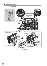
7-3-4 BALL DETECTING SENSOR
Core assembly (ball lift)
Station 2 (blue)
GUARD F
CABLE
HOLDER
LIFT PLUNGER C
Two pan head screws
(w/washers) (M4 x 6)
Unscrew Pan head screw
(w/washers) (M4 x 6)
BALL DETECTING SENSOR
Pan head screw
(w/washers)
(M3 x 16)
Cable clip
CABLE HOLDER
LIFT PLUNGER
C
Connector
Clearance
gap
Note
When attaching the new BALL
DETECTING SENSOR, make
sure that the sensor orientation
is as in the figure.
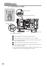
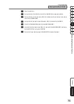
Remove the MAINT DOOR C on Station 2 (blue) using the service key.
Loosen the four pan head screws with washers (M4 x 6) to remove the GUARD F.
Unscrew the pan head screw with washers (M4 x 6), disconnect the harness connector, and
loosen the two cable clips to remove the CABLE HOLDER.
Unscrew the two pan head screws with washers (M4 x 6) to remove the LIFT PLUNGER C.
Unscrew the pan head screw with washers (M3 x 16) and disconnect the harness connector to
replace the BALL DETECTING SENSOR.
z
When attaching the new BALL DETECTING SENSOR, make sure that the sensor
orientation is as in the figure above.
Содержание PAC-MAN SWIRL
Страница 84: ...9 Parts List 84 27 29 28 18 19 25 26 24 21 23 22 28 31 20 30...
Страница 88: ...9 Parts List 88 39 31 40 29 25 26 22 27 34 23 35 24 21 28 37 20 30 38 32 36 33 40...
Страница 96: ...9 Parts List 96 9 5 Core Assembly 8 7 6 7 5 3 2 9 10 14 11 13 15 14 12 4 1 6 8...
Страница 98: ...9 Parts List 98 34 35 23 17 32 29 16 27 26 28 36 24 17 18 25 19 31 32 32 32 33 30 37 21 20 22 33...
Страница 104: ...9 Parts List 104 9 6 Cabinet Base Assembly 7 15 8 9 10 11 13 6 14 14 10 8 9 8 1 2 12 3 13 14 5 4 13...
Страница 108: ...9 Parts List 108 9 7 Acrylic Door Assembly 22 14 22 13 12 15 20 1 8 6 11 3 16 22 18 17 19 9 10 4 5 7 1 2 21...
Страница 112: ...112...
Страница 122: ......
Страница 123: ......
Страница 124: ......
Страница 125: ......


