


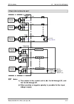
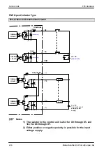
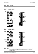
FP0 Hardware
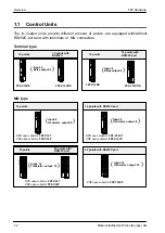
Control Units
2-4
Matsushita Electric Works (Europe) AG
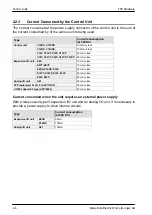
2.1.1
Status Indicator LEDs
These LEDs display the current mode of operation or the occurrence of an error.
LED
Description
RUN (green)
Illuminates when in the RUN mode and indicates the execution of a program. It flashes during
forced input/output.
PROG. (green)
Illuminates when in the PROG. mode and indicates that operation has stopped.
ERROR/ALARM
(red)
Flashes when an error is detected during the self-diagnostic function. Illuminates if a
hardware error occurs, or if operation slows because of the program, and the watchdog timer
is activated.
2.1.2
Mode Switch
This switch turns ON and OFF (RUN/PROG.) the operation of the FP0. The FP0 can
also be turned ON and OFF by the programming tool.
Switch position
Operation mode
RUN (upward)
This sets the RUN mode. The program is executed and operation begins.
PROG. (downward)
This sets the PROG. mode.
When performing remote switching from the programming tool, the position of the mode
switch and the actual mode of operation may differ. Verify the mode with the status
indicator LED. Otherwise, restart the FP0 and change the mode of operation with the
mode switch.
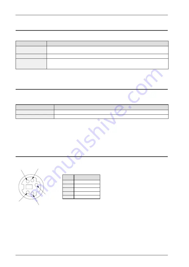
2.1.3
Tool Port
The tool port is used to connect a programming tool.
3
4
5
1
2
SG
SD (TXD)
RD (RXD)
+ 5 V
–
3
2
4
1
5
Abbreviation
Pin no.
Pin assignment
Содержание FP Series
Страница 12: ...Chapter 1 Overview...
Страница 21: ...FP0 Hardware Overview 1 10 Matsushita Electric Works Europe AG...
Страница 22: ...Chapter 2 Control Units...
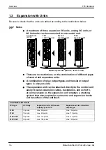
Страница 44: ...Chapter 3 Expansion I O Units...
Страница 67: ...FP0 Hardware Expansion I O Units 3 24 Matsushita Electric Works Europe AG...
Страница 68: ...Chapter 4 Analog I O Unit...
Страница 87: ...FP0 Hardware Analog I O Unit 4 20 Matsushita Electric Works Europe AG...
Страница 88: ...Chapter 5 FP0 I O Link Unit MEWNET F...
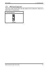
Страница 102: ...Chapter 6 Power Supply Unit...
Страница 105: ...FP0 Hardware Power Supply Unit 6 4 Matsushita Electric Works Europe AG...
Страница 106: ...Chapter 7 I O Allocation...
Страница 112: ...Chapter 8 Installation...
Страница 122: ...Chapter 9 Wiring...
Страница 139: ...FP0 Hardware Wiring 9 18 Matsushita Electric Works Europe AG...
Страница 140: ...Chapter 10 Trial Operation...
Страница 143: ...FP0 Hardware Trial Operation 10 4 Matsushita Electric Works Europe AG...
Страница 144: ...Chapter 11 Self Diagnostic and Troubleshooting...
Страница 156: ...Appendix A System Registers...
Страница 170: ...Appendix B Special Internal Relays...
Страница 174: ...Appendix C Special Data Registers...
Страница 183: ...FP0 Hardware Special Data Registers C 10 Matsushita Electric Works Europe AG...
Страница 184: ...Appendix D Dimensions...
Страница 195: ...FP0 Hardware Dimensions D 12 Matsushita Electric Works Europe AG...