background image

Page 12 of 14

4/21  IOM-MAC-700-INST

Nailor Industries Inc. reserves the right to change any information concerning product or specification without notice or obligation.

Nailor Industries Inc. reserves the right to change any information concerning product or specification without notice or obligation.

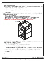
INSTALLATION INSTRUCTIONS:

The NBPI is located downstream of the HEPA filter where it makes the particles to become larger and are more easily filtered 

from the air. Follow the below steps for installation.
1.  Turn off the unit with the ON / OFF switch located on the back of the unit.
2.  Mount the NBPI on the brackets using the magnets provided with the unit.
3.  Make sure there is 2" (51) clearance from wires or other metal objects.
4.  Install the GPS-FC24-AC so that airflow is passing by both emitters at the same time.

CLEANING CYCLE:

NBPI is a self-cleaning device designed to clean the brushed every three days. However, you have the option to change the 

cleaning cycle by following the below steps

5.  Press the cleaning cycle button once.
6.  While cleaning is in progress press and hold the cleaning cycle button for 5 seconds.
7.  After LED light started flashing; pressing the cleaning cycle button again will change the days between cleaning.
8.  The number of flashes indicates the cleaning interval in days (3 flashes = 3 days, 5 flashes = 5 days).

CAUTION! NEVER TOUCH BRUSHES WHILE OPERATING, SHOCK MAY OCCUR.

TROUBLESHOOTING:

The NBPI is located downstream of the HEPA filter where it makes the particles to become larger and are more easily filtered 

from the air. Follow the below steps for troubleshooting.
•  If the unit is not working and LED not illuminated: 
  a.  Check the input voltage. Make sure proper voltage is applied to each terminal.

•  If wiper sticks on emitters or does not clean or contact emitters:
  a.  Adjust height of emitters: Loosen screw at base of emitter, gently push or pull emitter to a height where wiper just contacts 

emitter. Hold the emitter in place and tighten screw. Verify correct height after tightening screw.

•  If unit does not operate properly after verifying the above instructions, please contact Nailor for additional assistance.

Electrical listings: UL, cUL

Approval: UL 867, OSHPD Seismic (OSP), IAQP, CE

BIPOLAR IONIZATION

Содержание MAC-700

Страница 1: ...Mobile Air Cleaner Unit w HEPA Filter Model MAC 700 Read completely and save these instructions for future reference M A N U A L M A N U A L I O M Installation Operation Maintenance ...

Страница 2: ...RY TO PERSONS ALLOW ONLY QUALIFIED TECHNICIANS TO INSTALL AND SERVICE THE UNIT ALL PERSONS SHOULD OBSERVE THE FOLLOWING a Before servicing or cleaning unit disconnect and lock out power at the service panel to prevent electric shock or injury if the power is accidentally turned on Installation work and electrical wiring must be completed by qualified persons in accordance with all applicable codes...

Страница 3: ...OULD OBSERVE THE FOLLOWING a Eye damage may result from directly viewing the light produced by these lamps Never look at the lamps while they are on lit or illuminated To reduce the risk of exposure to UV radiation turn off all switches and disconnect power to all UV C devices before service or take UV radiation protective measures for personnel during servicing b Before servicing or cleaning unit...

Страница 4: ...system The MAC 700 is designed to pull air from all sides to increase its ability to collect biomass and dust from the floor The air will travel through a MERV 10 pre filter which captures large particles HEPA filter and UV C light before recirculating purified near sterile air up into the room The final 6 152 mm HEPA filter provides filtration that is 99 99 effective in the removal of microbial c...

Страница 5: ... resistant bases and will not produce ozone SAFETY INTERLOCK SWITCH MAC 700 includes mechanical interlock switches to ensure that the UV C assembly will be de energized when the door is opened Before UV C installation make sure the interlock switch is installed and properly wired to the control box Figure 2 Safety Interlock Switch Step 1 Handle UV C fixturing wearing soft cloth gloves and safety g...

Страница 6: ...ation emitted by the bulbs will degrade over the 9 000 operating hours time and will no longer provide the intended benefit however the characteristic blue glow may still be seen and generated HOUR METER AND RESET BUTTON MAC 700 is equipped with an hour meter that counts the number of hours that unit has been On The UV C lamps should be replaced when the hour meter number reaches to 9 000 After re...

Страница 7: ...ag in an outdoor trash can Step 1 Open the unit door using square head door key shipped with unit Two keys shipped with unit Step 2 To remove the HEPA filter rotate all three plastic knobs counterclockwise all the way up and loose the filter clips Lift the HEPA filter out of the unit Step 3 Unpack the new filter and inspect shipping damage If damage is found do not install in unit call the manufac...

Страница 8: ... right to change any information concerning product or specification without notice or obligation CONTROL BOX The MAC 700 contains a 11 x 8 279 x 203 control box that includes terminal blocks and transformer reset button and UV lights ballast Figure 6 Control Box Layout ...

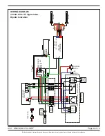
Страница 9: ...UV LIGHT UV LIGHT 10 NC NO COM 0 DOOR PANEL SAFETY SWITCH SPEED CONTROLLER RESET BUTTON HOUR METER 2 1 4 3 4 3 120 1 60 J BOX 8X6X4 SO CORD SIT 16 3 L1 N GND 4 3 2 1 BAS ALARM GND NEUTRAL BAS ALARM BK WH WH WH BK WH BK RD OFF ON BK YE GND YE YE TRANSFORMER 120 V 24 VAC CLASS 2 JUMPER WIRE ONLY 120 V BK BK RD YE YE LIGHT ON OFF SWITCH PRESSURE SWITCH LED SWITCH BK BN OR OR RD RD BK BN BK RD RD BK F...

Страница 10: ... GN GN UV LIGHT UV LIGHT 10 2 3 0 DOOR PANEL SAFETY SWITCH SPEED CONTROLLER RESET BUTTON HOUR METER 2 1 4 3 4 3 120 1 60 SO CORD SIT 16 3 L1 N GND 4 3 2 1 WH WH BK WH BK WH RD YE BL WH BL RD BK OR YE GND YE YE TRANSFORMER 120 V 24 VAC CLASS 2 JUMPER WIRE ONLY 120 V BK RD BK RD YE BL BK RD LIGHT ON OFF SWITCH PRESSURE SWITCH LED SWITCH RD YE YE YE RD RD RD YE BK RD RD BK FRONT VIEW YE BL BK RD TOP ...

Страница 11: ...th pathogens they disrupt the pathogens surface proteins rendering them inactive The technology delivers indoor air that s free of ozone and other harmful by products PRODUCT DESCRIPTION This device is an auto cleaning device handles up 2400 CFM and doesn t require maintenance with multiple mounting options STANDARD FEATURES INCLUDE Universal Voltage Input In Line ON OFF Switch Magnets for ease of...

Страница 12: ...ning cycle button once 6 While cleaning is in progress press and hold the cleaning cycle button for 5 seconds 7 After LED light started flashing pressing the cleaning cycle button again will change the days between cleaning 8 The number of flashes indicates the cleaning interval in days 3 flashes 3 days 5 flashes 5 days CAUTION NEVER TOUCH BRUSHES WHILE OPERATING SHOCK MAY OCCUR TROUBLESHOOTING Th...

Страница 13: ...bove steps to reassemble the motor blower assembly into the unit TROUBLE SHOOTING WARNING Disconnect the unit from the electrical power source before attempting to service the unit Unit will not run Confirm that the power cord is plugged into the building receptacle and power is present Confirm illuminated ON OFF push button is pushed in Check the speed controller and note that 1 Motor Blower is d...

Страница 14: ...r o l a n d D i s t r i b u t i o n S o l u t i o n s n a i l o r c o m Calgary Canada Tel 403 279 8619 Fax 403 279 5035 Houston Texas Tel 281 590 1172 Fax 281 590 3086 Toronto Canada Tel 416 744 3300 Fax 416 744 3360 Las Vegas Nevada Tel 702 648 5400 Fax 702 638 0400 ...

Отзывы: