Nagas SDM Series Скачать руководство пользователя страница 1


1385, boul. Lionel-Boulet, Varennes, Québec J3X 1P7         Toll Free: 1 888 514-8007  


Tel: 438 338-1101  


Fax: 450 922-5900


www.nagasinnovation.com


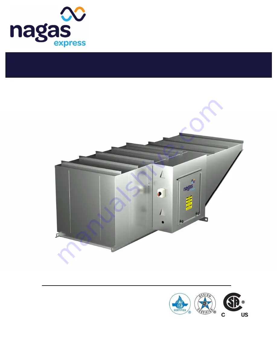
DIRECT GAS-FIRED MAKE-UP AIR HEATERS 

Indoor and Outdoor installation 


INSTALLATION AND OPERATION MANUAL


SDM(E) SERIES 

Rev. 4_2023 

Содержание SDM Series

Страница 1: ...nes Qu bec J3X 1P7 Toll Free 1 888 514 8007 Tel 438 338 1101 Fax 450 922 5900 www nagasinnovation com DIRECT GAS FIRED MAKE UP AIR HEATERS Indoor and Outdoor installation INSTALLATION AND OPERATION MA...

Страница 2: ...2 Fan adjustment 13 5 3 Motor check 13 5 4 Air volume measurement and check 14 5 5 Gas inlet pressure adjustment 14 5 6 Burner air differential pressure adjustment 14 5 7 Pilot adjustment 16 5 8 Burn...

Страница 3: ...aring lubrication 28 9 5 Vent terminals 28 9 6 Air Filters 29 9 7 Controls and sensors 29 9 8 Outdoor air intakes exhaust outlet mixing sections and dampers 29 9 9 Snow accumulation 29 9 10 Maintenanc...

Страница 4: ...the installation operation and service instruction in this manual Improper installation adjustment alteration service or maintenance can cause serious injury death or property damages Do not store or...

Страница 5: ...as Express units The application of the instructions given in this manual is one of the conditions of the warranty however it does not guarantee at any time conformity with the applicable laws rules c...

Страница 6: ...erty damage and or harm to the building occupants and will void the warranty of the equipment 1 4 Reception storage Immediately upon receipt of the equipment check the crating and contents for any dam...

Страница 7: ...on with normal maintenance such as filters or belts h products no longer at the site of the original installation i products installed or operated other than in accordance with the printed instruction...

Страница 8: ...direct gas fired make up air heater is intended for indoor or outdoor installation as a complete ventilation system with gas heating complete with factory installed air and gas controls This equipment...

Страница 9: ...ain flammable and toxic gas as well as any other harmful material in the make up air heater Where air ducts or plenums directly connected to the make up air heater create a pocket where gas could accu...

Страница 10: ...aged WARNING Injury or death can result from incorrect rigging and lifting these manoeuvres must be performed by qualified crane operator with proper equipment using appropriate and approved safety pr...

Страница 11: ...igned for suspended mounting without special mounting frame If you intend to suspend this equipment you must provide your own custom base mounting DO NOT USE lifting lugs to attach hanger rods This sp...

Страница 12: ...should not exceed psig 14 inches of water for all the SDM E series heaters If the gas inlet pressure exceeds psig 14 inches of water a high pressure regulator must be installed This regulator must be...

Страница 13: ...m of the unit into the ventilation system matches the unit rating label Failure to perform a proper air balance can cause injury or death damage to the equipment property damage system operational pro...

Страница 14: ...86 Pa 100 150 Min 6 in w c 1493 Pa or 8 in w c 1991 Pa Min 8 in w c 1991 Pa 200 Min 6 in w c 1493 Pa or 13 in w c 3235 Pa Depend on burner configuration See name plate for exact value Table 4 Gas pres...

Страница 15: ...air pressure gage read the differential pressure as shown Figure 3 Pressure differential The value of the differential pressure drop observed through the profile plate must be set between 0 60 in w c...

Страница 16: ...m both adjustment plates should be equidistant from the burner Then read the differential pressure again and repeat the operation if necessary NOTE These adjustments may change the airflow rate of the...

Страница 17: ...to the required gas pressure indicated on the name plates of the unit The adjustment is made using the main burner pressure regulator figure 5 For units with a capacity over 1000 MBH use the regulato...

Страница 18: ...selector TD 114 to the desired final temperature refer to local code for maximum temperature allowed This selector is located either in the control panel on the unit or the remote control station NOT...

Страница 19: ...air pressure difference across the burner 5 ln high volume mode the outside air damper opens completely the profile plate damper opens wider and modulates its position in order to maintain the requir...

Страница 20: ...of inlet or outlet air dampers 8 Turn ON main disconnect 9 Press the reset button of the flame safeguard relay 10 Ensure that the air inlet and outlet dampers are operating properly 11 Ensure that th...

Страница 21: ...n see table on next page 2 Pressing down the reset button brings the flame safeguard relay back to its normal operating mode 8 2 Status of warning lights FIREYE The table below lists the most importan...

Страница 22: ...ondary circuit fuse 4 Check the position of the switch on the remote control panel it should be set to BURNER 5 Check the contactor indicating that the exhaust fan is in operation 6 Press down the res...

Страница 23: ...VDC over the entire modulation range 4 Refer to the manufacturer SYMPTOMS ACTIONS CODE 21 Open air pressure switch NOTE While the heater is in operation the safe contacts located between terminals 6 a...

Страница 24: ...o the manufacturer CODE 56 Faulty amplifier 1 Replace the amplifier 2 Refer to the manufacturer 8 4 Maxitrol Troubleshooting check list SYMPTOMS POSSIBLE CAUSES ON SITE CHECKS ACTIONS A No gas flow l...

Страница 25: ...nals 1 and 2 and TD114 terminals 1 and 3 11 Check TS114 for open circuits Follow step 4 12 Make sure jumper is connected 10 Correct wiring if necessary 11 If a modulating signal is obtained check TS11...

Страница 26: ...place the modulating valve head if the resistance is under 40 ohms 26 Correct the wiring if a short circuit is found K Discharge air temperature too low when the room thermostat controls the burner 27...

Страница 27: ...when servicing controls or critical components Wiring errors can cause improper and dangerous operation Verify proper operation after servicing NOTICE For additional information always refer to the p...

Страница 28: ...INTERVALS CAUTION OVERTIGHTENING SET SCREWS CAN DAMAGE BEARINGS 9 4 Bearing lubrication Fan bearings Some fans depending on equipment model and size have permanently lubricated sealed ball bearings wh...

Страница 29: ...r operation and repair or replace any faulty controls Check all damper hardware settings every three months Replace blown fuses with equivalent size and type fuse Failure to do so can result in damage...

Страница 30: ...aks in the piping fittings and valves Inspect all electric connections Ensure that the blower and motor are firmly anchored Inspect the flame detector and pilot ignitor electrode change if necessary I...

Страница 31: ...ing switch Verify control wiring wire gauge Verify supply voltage main disconnect Verify supply gas pressure Notes ____________________________________________________________________________________...

Страница 32: ...__________________________________________________________________________________________ __________________________________________________________________________________________ __________________...

Страница 33: ...o speed VFD When the unit is running the display should show the current frequency of the drive 1 Push on the jog dial 3 The screen should display rEF 2 Turn the jog dial up to COnF configuration then...

Страница 34: ...he jog dial up to FULL then push the jog dial 4 Turn the jog dial up to SET settings then push the jog dial 5 Turn the jog dial up to LSP minimal speed equivalent to the input signal 0 Volt then push...

Страница 35: ...1385 boul Lionel Boulet Varennes Qu bec J3X 1P7 Toll Free 1 888 514 8007 Tel 438 338 1101 Fax 450 922 5900 www nagasinnovation com 35 of 35...

Отзывы: