1
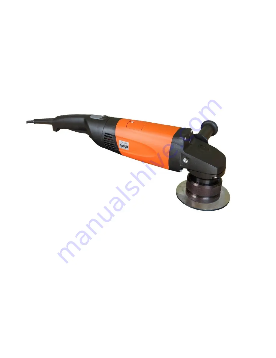
MANUAL BEVELLING AND
DEBURRING SYSTEM B15
AIR
Ord. no. 27,220
Operation manual for the device
SUBJECT TO CHANGE
Страница 1: ...1 MANUAL BEVELLING AND DEBURRING SYSTEM B15 AIR Ord no 27 220 Operation manual for the device SUBJECT TO CHANGE...
Страница 2: ...l specifications 6 Accessories 7 Machine equipment 7 Control elements B15 AIR 8 Use 9 Setting the removal size 9 Bevelling 11 Bevel angle and shape change Milling head replacement 12 Replacement of in...
Страница 3: ...s used in the manual are intended to emphasize the important information regarding the safety and operation of the machine Attention Information important for the personal safety of the operating staf...
Страница 4: ...4 3 Identification data and CE Declaration of Conformity The identification data of machine B15 ELECTRA are listed on the label placed on the drive unit...
Страница 5: ...potential warranty defects are removed free of charge and without undue delay so that the buyer is able to use the article the way they desire Should the buyer claim liability for warranty unrelated d...
Страница 6: ...ine in humid environment and protect from high moisture Ensure good lighting at the workplace to prevent the risk of potential injury or eyesight damage Caution the tool milling machine is sharp with...
Страница 7: ...0 incl inserts screws bolts and roller 27 223 Milling head 37 5 incl inserts screws bolts and roller 27 227 Milling head 45 incl inserts screws bolts and roller 27 222 Milling head 50 incl inserts scr...
Страница 8: ...e the tools The review of tools is defined in chapter 8 Accessories or in the catalogue of N KO Machines and contact your supplier 10 Control elements B15 AIR Fig 10 0 1 A Handle B Motor body C Scale...
Страница 9: ...ig 10 0 1 position F Turn the guiding plate fig 10 0 1 position G for setting the reduction size You can read the setting on the scale fig 10 0 1 position C Stupnice je pouze orienta n a v sledn b r m...
Страница 10: ...fig 10 0 1 position G and placing to the material edge 45 For full bevel P 15mm is required turn the thrust plate by 5 2 revolutions Chip no Hypotenuse P Bevel height A Number of rpm of the thrust pl...
Страница 11: ...ition G was in contact with material at maximum possible surface Slowly move the machine to the material until you feel the milling machine is in reduction CAUTION The rebound is possible at this mome...
Страница 12: ...fig 10 0 1 position F Turn the guiding plate fig 10 0 1 position G for complete disassembly from the machine Secure the spindle against turning with attached wedge fig 11 2 1 position A Use head scre...
Страница 13: ...chine damage If the cutting inserts are worn or damaged or cracked they must be replaced Attach the wrench fig 11 3 1 position D release the screws used for fastening the indexable inserts fig 11 3 1...
Страница 14: ...er cable In case of damage have it replaced in an authorised service shop authorised to perform the such repairs Contact your supplier Important The moving parts threads and mechanical connections mus...
Страница 15: ...15 13 1 List of spare parts...
Страница 16: ...16...
Страница 17: ...17...
Страница 18: ...ELECTRA All rights reserved No part of this publication may be reproduced without the previous consent granted by the company N KO N KO spol s r o T borsk 398 22 293 01 Mlad Boleslav Czech republic p...