NATIVE-C1
T
ECHNICAL
R
EFERENCE
M
ANUAL
V1.0
C
HASSIS
D
ESIGN
- 34 -
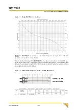
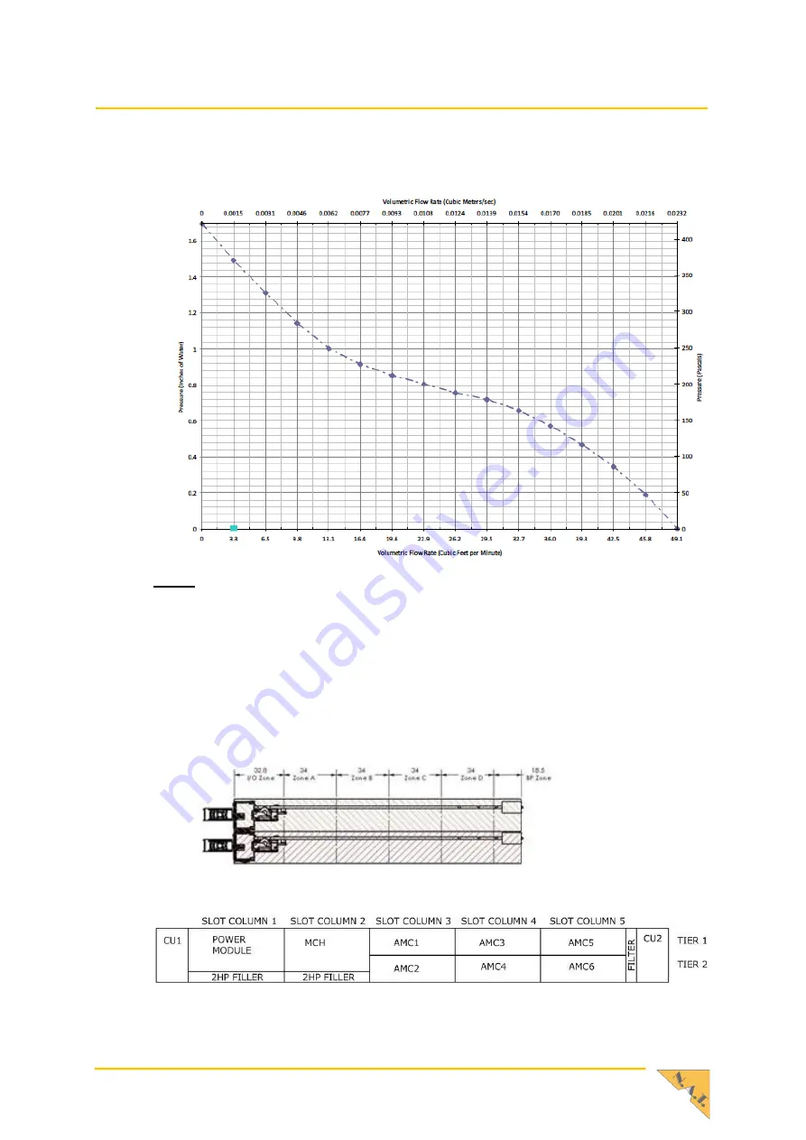
Figure 11
–
Single Mid-Size Slot Fan Curve
Note:
The
NATIVE-C1
can achieve volume metric flow rates in excess of 75 CFM and
pressures in excess of 1.5 inches of water.
The cross section drawing of the
NATIVE-C1
below shows 5 zones defined in the AMC spec
plus a 6th zone (BP Zone), which exists in MicroTCA systems as there is room for air to flow
between the backplane connectors. The CFP (Computational Fluid Dynamics) model results are
shown below for all zones in all bays.
Figure 12
–
Airflow Uniformity for each Bay and the AMC Zones
Upper Mid-Size Bay
Lower Mid-Size Bay
Содержание NATIVE-C1
Страница 15: ...NATIVE C1 TECHNICAL REFERENCE MANUAL V1 0 CHASSIS DESIGN 15 Table 4 AMC Connector Pin Assignment...
Страница 16: ...NATIVE C1 TECHNICAL REFERENCE MANUAL V1 0 CHASSIS DESIGN 16 Table 5 MCH Tongue 1 Connector Pin Assignment...
Страница 17: ...NATIVE C1 TECHNICAL REFERENCE MANUAL V1 0 CHASSIS DESIGN 17 Table 6 MCH Tongue 2 Connector Pin Assignment...
Страница 18: ...NATIVE C1 TECHNICAL REFERENCE MANUAL V1 0 CHASSIS DESIGN 18 Table 7 MCH Tongue 3 Connector Pin Assignment...
Страница 19: ...NATIVE C1 TECHNICAL REFERENCE MANUAL V1 0 CHASSIS DESIGN 19 Table 8 MCH Tongue 4 Connector Pin Assignment...
Страница 32: ...NATIVE C1 TECHNICAL REFERENCE MANUAL V1 0 CHASSIS DESIGN 32 Figure 8 Airflow Figure 9 Filter Performance...
Страница 37: ...NATIVE C1 TECHNICAL REFERENCE MANUAL V1 0 CHASSIS DESIGN 37 Figure 16 Typical Airflow Patterns...


