


NATIVE-C1
T
ECHNICAL
R
EFERENCE
M
ANUAL
V1.0
C
HASSIS
D
ESIGN
- 26 -
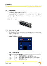
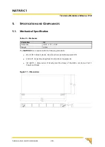
4.2.
Cooling Unit
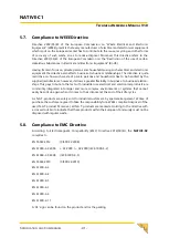
The
NATIVE-C1
is equipped with two cooling units.
Please note:
The picture below shows an older version of the Cooling Unit for illustration
purpose only. Cooling Units of the
NATIVE-C1
hardware version 1.1 and higher are
not
mechanically compatible
to hardware version 1.0!
Figure 5
–
Cooling Unit
4.2.1.
Front Panel and LEDs
The front panel of the
NATIVE-C1
Cooling Unit
is equipped with four LEDs. The functionality
is described in the table below.
Figure 6
–
Cooling Unit Front Panel
HSMA
Diag
HS
RDY
OOS
Table 12
–
LED Functionality
LED
Colour
Function
OOS
Red
Out Of Service; indicates a failure condition
i.e. fans are not turning or the temperature is too high
RDY
Yellow
Blinking indicates the heartbeat of the on-board micro controller
HSMA
Yellow
Indicates IPMI activity
HS
Blue
MicroTCA hot swap LED
Содержание NATIVE-C1
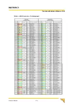
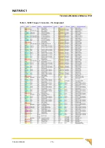
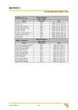
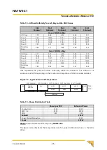
Страница 15: ...NATIVE C1 TECHNICAL REFERENCE MANUAL V1 0 CHASSIS DESIGN 15 Table 4 AMC Connector Pin Assignment...
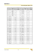
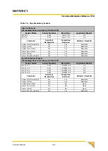
Страница 16: ...NATIVE C1 TECHNICAL REFERENCE MANUAL V1 0 CHASSIS DESIGN 16 Table 5 MCH Tongue 1 Connector Pin Assignment...
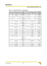
Страница 17: ...NATIVE C1 TECHNICAL REFERENCE MANUAL V1 0 CHASSIS DESIGN 17 Table 6 MCH Tongue 2 Connector Pin Assignment...
Страница 18: ...NATIVE C1 TECHNICAL REFERENCE MANUAL V1 0 CHASSIS DESIGN 18 Table 7 MCH Tongue 3 Connector Pin Assignment...
Страница 19: ...NATIVE C1 TECHNICAL REFERENCE MANUAL V1 0 CHASSIS DESIGN 19 Table 8 MCH Tongue 4 Connector Pin Assignment...
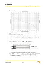
Страница 32: ...NATIVE C1 TECHNICAL REFERENCE MANUAL V1 0 CHASSIS DESIGN 32 Figure 8 Airflow Figure 9 Filter Performance...
Страница 37: ...NATIVE C1 TECHNICAL REFERENCE MANUAL V1 0 CHASSIS DESIGN 37 Figure 16 Typical Airflow Patterns...