background image

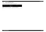
6.3.4 Counter Initialization Menu

366

6.3 Maintenance Mode 2 Menu

VJ628XE-M-00

6.3.4

Counter Initialization Menu

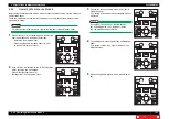
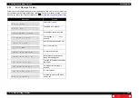
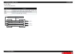
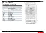
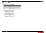
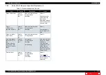
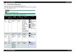
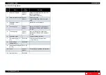
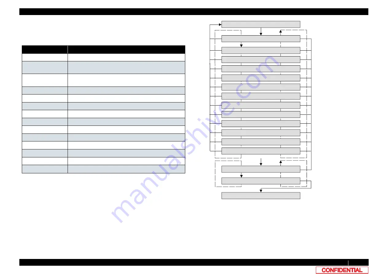
This menu is used to initialize the life counters. 
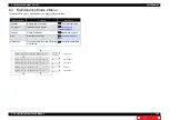
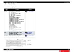
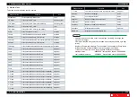
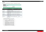
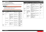
The parameters that can be initialized in this menu are as follows.

Diagnosis item

Contents 

Print Num

total print counter.

Print Info.

number of printed copies per mode, print area per mode, and the 
number of printed copies per effect

ALL

Timer,Life counter,Mechanical counter,Mechanical adjustment 
values,Head ID.

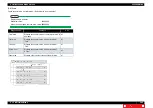
Timer

Timer.

CR Motor

CR motor life counter.

PF Motor

PF motor life counter.

HeadUnit

Head nozzle life counter

Wiper

Wiper life counter

Pump

Pump life counter

CPump1

Circulation Pump1 life counter

CPump2

Circulation Pump2 life counter

Cutter

Cutter life counter

Unlock Pos.

the position of unlocking Head lock

Waste Ink

Waste Ink amount counter

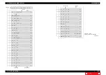
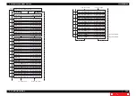
[Enter]

>@

>!@

[Enter]

㹇㹬㹧㹲㸬ࠉ㸴㸸㹆㹣㹟㹢ࠉ㹓㹬㹧㹲

㹇㹬㹧㹲㸬ࠉ㸵㸸㹕㹧㹮㹣㹰

㹇㹬㹧㹲㸬ࠉ㸶㸸㹎㹳㹫㹮

㹇㹬㹧㹲㸬ࠉ㸳㸸㹎㹄ࠉ㹋㹭㹲㹭㹰

㹇㹬㹧㹲㸬㸯㸰㸸㹓㹬㹪㹭㹡㹩ࠉ㹎㹭㹱㸬

㹇㹬㹧㹲㸬㸯㸯㸸㹁㹳㹲㹲㹣㹰

㹇㹬㹧㹲㸬ࠉ㸲㸸㹁㹐ࠉ㹋㹭㹲㹭㹰

㹇㹬㹧㹲㸬㸯㸱㸸㹕㹟㹱㹲㹣ࠉ㹇㹬㹩

㹇㹬㹧㹲㹧㹟㹪㹧㹸㹣㸽ࠉࠉࠉࠉࠉࠉ㹗㹣㹱

㹇㹬㹧㹲㹧㹟㹪㹧㹸㹣㸽ࠉࠉࠉࠉࠉࠉࠉ㹌㹭

㹇㹬㹧㹲㹧㹟㹪㹧㹸㹣ࠉ㹎㹟㹰㹟㹫㹣㹲㹣㹰

>@

[Enter]

[Cancel]

[Cancel]

>!@

㹇㹬㹧㹲㸬ࠉ㸰㸸㹎㹰㹧㹬㹲㹇㹬㹤㹭㸬

㹇㹬㹧㹲㸬ࠉ㸱㸸㸿㹊㹊

㹇㹬㹧㹲㸬ࠉ㸯㸸㹎㹰㹧㹬㹲ࠉ㹌㹳㹫

㹋㹟㹧㹬㹲㹣㸬㸰㸸㹇㹬㹧㹲㹁㹭㹳㹬㹲㹣㹰

㹇㹬㹧㹲㸬ࠉ㸷㸸㹁㹎㹳㹫㹮㸯

㹇㹬㹧㹲㸬㸯㸮㸸㹁㹎㹳㹫㹮㸰

[Enter]/
[Cancel]

Содержание Valuevet VJ-628X

Страница 1: ...VJ628XE M 00 VJ 628X MAINTENANCE MANUAL ...

Страница 2: ...er section 67 3 3 1 Replacing Panel Board 67 3 3 2 Replacing Cover Switch Assy 68 3 3 3 Replacing Switch Lever 69 3 3 4 Replacing Cover R Cable Assy 70 3 3 5 Replacing Switch Panel Cable Assy 71 3 4 Replacing Frame section 72 3 4 1 Replacing Media Holder 72 3 4 2 Replacing Scroller Holder Roller Assy 73 3 4 3 Replacing Adsorption Fan 74 3 4 4 Replacing Adsorption Fan Cable 75 3 5 Replacing Board B...

Страница 3: ... Replacing PG Origin Sensor Cable 123 3 8 9 Replacing Cutter Holder Assy 124 3 8 10 Replacing Cutter Solenoid Assy 125 3 8 11 Replacing Cutter Solenoid Cable 127 3 8 12 Replacing Mini Latch 128 3 8 13 Replacing Roller Arm Assy 129 3 8 14 Replacing Valve head 130 3 8 15 Replacing Head 134 3 8 16 Replacing Head FFC 139 3 8 17 Replacing Carriage Assy 141 3 8 18 Replacing Head FG Assy 145 3 9 Replacin...

Страница 4: ...itch to Board Manager Mode 225 4 3 19 Maintenance Panel 226 4 3 20 Terminating Application 228 4 4 X Speed Reduction Belt Tension Adjustment 229 4 4 1 Adjustment Procedure 229 4 5 PF Encoder Position Adjustment 230 4 5 1 Adjustment Procedure 230 4 6 CR Belt Tension Adjustment 231 4 6 1 Adjustment procedure 231 4 7 Head Adjustment 232 4 7 1 Head Alignment Horizontal Slant 232 4 7 2 Head Alignment V...

Страница 5: ... Running Menu 330 5 11 1 CR Motor Endurance Menu 331 5 11 2 PF Motor Endurance Menu 332 5 11 3 Cutter Menu 333 5 11 4 Pump endurance Menu 334 5 11 5 CPump endurance Menu 335 5 11 6 Head Lock Menu 336 5 11 7 Wiper Endurance Menu 337 5 11 8 Print Head Endurance Nozzle Print Menu 338 5 11 9 General Endurance Menu 339 5 11 10Endurance Running Check Menu 340 5 12 Media Feed Menu 341 5 13 Media Initial ...

Страница 6: ...81 8 2 Part Names and Functions 382 8 2 1 Appearance 382 8 2 2 Operation panel 383 8 3 Printer Status 386 8 3 1 Operating Status Type when using Jig Panel 386 8 3 2 Switching Operation Status when using Jig Panel 387 9 Specifications 9 1 Introduction 389 9 2 Product Specifications 390 9 2 1 Main Unit Specifications 390 9 3 Interface specification 391 9 3 1 Network interface specification 391 9 4 O...

Страница 7: ...y and product names may be registered trademarks or product names Warranty Limitations 1 MUTOH INDUSTRIES LTD warrants part repair or replacement as a sole measure only if a failure is found in the system or in the materials and workmanship of the product the seller produced However if the cause of failure is uncertain decide the action after due mutual consultation 2 The warranty shall not apply ...

Страница 8: ...them 3 Parts Replacement Explains the procedures of replacement and removal of the service parts of the printer 4 Adjustment Explains the adjusting procedures of the printer parts 5 Self Diagnostic Mode Explains the self diagnostic functions of the printer 6 Maintenance Mode 2 Explains the maintenance mode2 of the printer 7 Maintenance Explains daily maintenance of the printer 8 Product Overview E...

Страница 9: ...VJ628XE M 00 9 Revison Reason Chapter Section Contents Page No Errata Remarks 00 New ...

Страница 10: ...10 VJ628XE M 00 1 Safety Instructions 1 1 Introduction 11 1 2 Types and Meanings of Warnings 11 1 3 Warning Labels 12 1 3 1 Location and Type of Warning Labels 12 ...

Страница 11: ...e contents of warning labels attached to the printer are categorized into the following five types depending on the degree of risk or the scale of the accident Make sure to understand the meaning of the following warning terms and follow the instruction in this manual Table 1 1 Explanation of safety terms Safety terms Details Must be followed carefully to avoid death or serious bodily injury Must ...

Страница 12: ...e Warning Labels Make sure to note the following when handling the warning labels NOTE Make sure that all warning labels can be recognized If the text or illustrations cannot be seen clearly clean or replace the label When cleaning warning labels use a cloth with water or neutral detergent Do not use a solvent or gasoline If a warning label is damaged lost or cannot be recognized replace the label...

Страница 13: ...2 2 3 Errors Requiring Reboot 21 2 2 4 Error Messages during File Transmission 32 2 3 Troubleshooting Without Error Messages 34 2 3 1 Initial Operation Problems 34 2 3 2 Media Feed Problems 38 2 3 3 Printing Problems 39 2 3 4 Noise Problems 51 2 3 5 Online Function Problems 54 2 3 6 Other Problems 55 2 3 7 Problems in Using MUTOH Service Assistance 57 ...

Страница 14: ...ssagesIf cause of errors damage and recovery actions are not found in this chapter or the machine cannot restore to normal status please contact the distributor you purchased the product from or our customer support center No Trouble Contents Reference 1 When the message is displayed Trouble with an error message displayed on Operation panel when the printer is malfunctioning 2 2Troubleshooting wi...

Страница 15: ...interlock cable is securely connected to MAIN board 5 Are F cover R sensor and F cover L sensor damaged Replace F cover R sensor and F cover L sensor 6 Check the operation of Front cover sensor in Sen Cover in the self diagnosis function Replace Front cover sensor if it is not working properly 5 4 4Sensor Menu 3 3 4Replacing Cover R Cable Assy 7 MAIN board may be damaged Replace MAIN board 3 5 10R...

Страница 16: ...No media Media is not loaded 1 Check if there is paper in Sen Rear in the self diagnosis function If No media is displayed even when paper is loaded replace P Rear Sensor 5 6 1Rear Edge Sensor Adjustment 3 6 14Replacing P_REAR Sensor 2 Does the media in use have low reflectance Instruct the user that media with low reflectance cannot be used 3 Is the cable of P Rear Sensor placed under Paper guide...

Страница 17: ...he cable of P EDGE Sensor connected securely Securely connect it to CR board connector 3 8 4Replacing CR Board 5 Is the cable of P Rear Sensor connected securely Securely connect it to MAIN board connector Electric Wiring Diagram 6 Check the sensitivity of the sensor in Sen EdgeAD in the self diagnosis function Replace P_EDGE Sensor 5 6 1Rear Edge Sensor Adjustment 7 Does the media in use have low...

Страница 18: ...ble may be damaged Replace it 3 11 3Replacing Cartridge Holder 8 JUNC_ID cable may be damaged Replace it 3 5 12Replacing JUNC_ID Cable 9 JUNC_FFC may be damaged Replace it 3 5 13Replacing JUNC_FFC 10 JUNCTION Board may be damaged Replace it 3 5 11Replacing JUNCTION Board 11 MAIN board may be damaged Replace it 3 5 10Replacing MAIN Board 4 No cartridge Ink color is displayed in the Ink cartridge is...

Страница 19: ...roken Chip S C Color Err S C Ink Err S CCode Err A dedicated S C card may be malfunction 1 Check if the message is displayed after turning off the printer and turning it back on When the message is displayed Refer to the check item 2 Operation Manual 2 Check if the dedicated Smart chip cards are used 3 Check if the dedicated Smart chip cards are broken or the chip portion is damaged Replace with t...

Страница 20: ...nter after replacing it 3 10 7Replacing Maintenance Assy 6 3 4 Counter Initialization Menu 9 Life Times CR Motor The operational life of CR motor has almost expired Replace CR motor as necessary Clear the counter after replacing it 3 6 1Replacing CR Motor 6 3 4 Counter Initialization Menu 10 Life Times PF Motor The operational life of PF motor has almost expired Replace PF motor as necessary Clear...

Страница 21: ...e error message on the LCD The error can be cancelled by removing the error causes and restarting the machine 1 CPU system serious error Table 2 3 Symptoms and Check items for CPU System Serious Errors No Message Event symptom Check item Action Reference 1 E016 Interrupt 00 Interruption exception error An anomaly is detected during interruption process 1 Check AC power supply and printer periphera...

Страница 22: ... E016 TLB S 03 Data border exception TLB exception store error An anomaly is detected in data border Or TLB exception is detected while storing data Replace MAIN board 3 5 10Replacing MAIN Board 5 E016 AddErr L I 04 Address exception error load or command fetch Address error is detected while loading or fetching command 6 E016 AddErr S 05 Address exception error store An address error is detected ...

Страница 23: ...eplacing MAIN Board 9 E016 SystemCall 08 System call exception error An anomaly is detected in system call 10 E016 BreakPoint 09 Break point exception error An anomaly is detected in break point 11 E016 Reserved 10 Reserved command exception error An anomaly is detected in reserved command 12 E016 Copro 11 Coprocessor disabled exception error An anomaly is detected in coprocessor Table 2 3 Symptom...

Страница 24: ...oard 14 E016 Trap 13 Arithmetic overflow exception error Overflow is detected 15 E016 Floating 15 Floating decimal point exception error An anomaly is detected in floating decimal point 16 E016 Watch 23 Watch exception error An anomaly is detected in Watch 17 E016 WatchDog 32 Watchdog time out exception error A time out is detected in Watchdog 18 E016 Abort Err 33 Abort error Abort is detected 19 ...

Страница 25: ...he value displayed on the panel changes as follows Front feed direction Increase Back feed direction Decrease 5 Check if DC42V is correctly supplied from Power board using the tester Remove paper jam Check the connection of the following connectors of MAIN board PF motor cable connector PF_ENC connector Connector that is connecting PF motor and PF motor relay If Main power board is damaged replace...

Страница 26: ...by hand and see if the value displayed on the panel changes as follows Front feed direction Increase Back feed direction Decrease 4 PF encoder may be damaged 5 PF encoder may be damaged 6 MAIN board may be damaged Check the connection of the following connectors of MAIN board PF motor cable connector PF_ENC connector Connector that is connecting PF motor and PF motor relay Replace PF encoder If Ma...

Страница 27: ...e panel changes as follows Front feed direction Increase Back feed direction Decrease 6 PF encoder may be damaged 7 PF motor may be damaged 8 Power board may be damaged 9 MAIN board may be damaged Explain the user about the recommended media weight Remove paper jam check if Media holder and Head are damaged and check if the same error occurs Check the connection of the following connectors of MAIN...

Страница 28: ...rs MAIN board CR motor connector CR_FFC connector CR board CR_FFC connector Check the connection to CR motor is appropriate Check if the tensions of CR speed reduction belt and Steel belt are appropriate Replace the following parts T fence CR encoder CR_FFC CR motor CR board MAIN board 3 8 5Replacing CR Encoder 5 4 7Record Menu 3 6 8Replacing T Fence 7 5Lubrication Bonding 3 5 10Replacing MAIN Boa...

Страница 29: ...n the self diagnosis function When Carriage lock solenoid is malfunctioning replace it 3 8 1Releasing Carriage Lock 8 MAIN board may be damaged Replace MAIN board 3 5 10Replacing MAIN Board 8 E072 Err CR Current An overload condition is detected in CR motor Y axis during printer operation 9 E074 Err CR2 Current 10 E092 Err CR Overload 11 E075 Head Temp This indicates that Heat transistor is malfun...

Страница 30: ... damaged 5 Head may be damaged 6 CR board may be damaged 7 MAIN board may be damaged 1 Make sure to connect Head FFC surely 2 Make sure to connect CR_FFC surely 3 Replace Head FFC 4 Replace CR_FFC 5 Replace Head 6 Replace CR board 7 Replace MAIN board 3 8 16 Replacing Head FFC 3 9 3 Replacing CR FFC 3 8 15 Replacing Head 3 5 10Replacing MAIN Board 16 E 087 Err H trans Th This indicates that Head t...

Страница 31: ...1 E 154 Err AC Volt Low Interception of the power supply to a printer or the supply voltage decreased 1 AC cable may have unplugged 2 Instantaneous power failure may have occurred 3 Power board may be damaged Plug AC cable securely Operation Manual Reboot the printer Operation Manual Replace Power board 3 5 1Replacing Power Board 22 E227 Err Heater SSR This indicates that Heater Off is not worked ...

Страница 32: ...ving the problem retransfer the firmware 4 Transfer failed Check sum error File checksum error is detected 1 Retransfer the firmware 2 If this does not solve the problem check if the transferred firmware was the correct file 5 Transfer failed Wrong size xxxxxxxx Received wrong sized data Check if the program file is correct After checking retransfer the data 6 Transfer failed Incompatible F W Inco...

Страница 33: ... month data xx 15 Transfer failed Wrong day xx Received wrong date data xx 16 Transfer failed Wrong hour xx Received wrong time data xx 17 Transfer failed Wrong min xx Received wrong minute data xx 18 Transfer not ready Transfer is not available Check if the LED display on Operation panel is in standby state in Board manager mode Press an arbitrary button on Operation panel to set the panel displa...

Страница 34: ...cut or shorted out Replace Panel FFC 3 3 1Replacing Panel Board 4 Panel unit may be damaged Replace Panel unit 5 Inlet may be damaged Replace Inlet 3 5 6Replacing AC Inlet 6 Power board may be damaged Replace Power board 3 5 1Replacing Power Board 7 MAIN board may be damaged Replace MAIN board 3 5 10Replacing MAIN Board 2 LCD display malfunction When using Jig Panel 1 Check the connection of Panel...

Страница 35: ...n Sen INK ID in the self diagnosis function while specified ink bags are securely inserted Follow the same procedure as when error about S C card is displayed to take appropriate measures After adjustment and replacement perform Initial ink charge in Check InkCharg InkCharge Normal in the self diagnosis function 2 2 2Errors with Message 5 9 2Parameter Update Menu 6 MAIN board may be damaged Replac...

Страница 36: ...lacing Ink Tube 6 Is Ink tube bent or does it have scratches or air leakage Replace the damaged Ink tube and check if the cleaning operation makes the ink flow When ink flow is confirmed perform initial ink charge again 3 9 4Replacing Ink Tube 5 5Ink Charging Menu 7 Check the following points and connections and of Head FFCs on the CR board side and the head side Is Head FFC obliquely inserted Cor...

Страница 37: ...g MAIN Board 3 6 14Replacing P_REAR Sensor 5 Is DC cable between Power board and MAIN board correctly connected Reconnect DC cable Replace DC cable 3 5 1Replacing Power Board 6 MAIN board may be damaged Replace MAIN board 3 5 10Replacing MAIN Board 7 Power board may be damaged Replace Power board 3 5 1Replacing Power Board 7 The printer does not recognize the installed ink cartridges 1 Does the ne...

Страница 38: ...ors of the following MAIN board Suction FAN relay Replace the Suction FAN Replace the Suction FAN s cable which doesn t work properly 3 5 10Replacing MAIN Board 3 Media wrinkles during media initialization or printing 4 Media tears during media initialization or printing 4 Are you using media whose edges are curled up Instruct the users to use the recommended media and how to use Media holder Oper...

Страница 39: ...nce Replace Flushing box Operation Manual 4 Cleaning does not mend the clogged nozzles or skewed ink discharge 2 Is cleaning sufficiently done Perform cleaning twice in a row Operation Manual 3 Is ink adhered on Wiper 4 Check if Wiper correctly operates in Sen Wiper in the self diagnosis function After wiping the surface of Cleaning wiper with the attached Cleaning stick perform cleaning twice in ...

Страница 40: ... 2Parameter Update Menu 4 Cleaning does not mend the clogged nozzles or skewed ink discharge 10 Is Ink tube folded Replace Ink tube and see if the cleaning operation makes the ink flow When ink flow is confirmed perform initial ink charge again 3 9 4Replacing Ink Tube 5 5Ink Charging Menu 11 Is Head damaged Replace the damaged Head 3 8 15 Replacing Head 12 CR board may be damaged 13 MAIN board may...

Страница 41: ...ing Ink Tube 5 5Ink Charging Menu 6 Does the next self diagnosis function correctly operate while specific cartridges are securely inserted Ink detection in Ink END Cartridge detection in Ink NOT Follow the same procedure as when Ink NOT is displayed to take appropriate measures After adjustment and replacement perform Initial ink charge in Update Head Rank in the self diagnosis function 2 2 2Erro...

Страница 42: ...iquely Correctly plug Head FFC to the connector again 3 8 15 Replacing Head 3 8 4Replacing CR Board 2 Is CR_FFC obliquely inserted Reinsert the connectors of CR_FFC 3 5 10Replacing MAIN Board 3 8 4Replacing CR Board 3 CR_FFC may be damaged Replace CR_FFC 3 9 3 Replacing CR FFC 4 Head FFC may be damaged Replace Head FFC 3 8 15 Replacing Head 5 Is Head damaged Replace the damaged Head 3 8 15 Replaci...

Страница 43: ...ensation value correct Set media feed compensation value to more than 500mm to adjust 5 12Media Feed Menu 5 Is Head adjusted correctly When replacing Head adjust it using the self diagnosis function Excluding the input of Head rank 4 2Adjustment Item 6 Are the nozzles of Head clogged Perform cleaning 2 3 3Printing Problems 7 Is a recommended print mode used Have the effects been changed If the mod...

Страница 44: ...Is T fence dirty Clean T fence If T fence is still dirty after cleaning or damaged replace it 3 6 8Replacing T Fence 10 White or black lines appear on printed media Continued 16 Does Pressure roller rotate smoothly while Pressure lever is raised If paper dust or pieces of paper is adhered around Pressure roller wipe it off with a soft damp cloth Operation Manual 17 Is Pump motor rotating during cl...

Страница 45: ...CR board 3 8 4Replacing CR Board 10 White or black lines appear on printed media Continued Replace MAIN board 3 5 10Replacing MAIN Board 11 The printed borders are blurred 1 Does cleaning remedy the situation Perform cleaning twice in a row Operation Manual 2 Are you using the media recommended by MUTOH Reload the media recommended by MUTOH and check again Operation Manual 3 Is Head correctly adju...

Страница 46: ...rge wait for more than six hours before printing Print quality cannot be guaranteed until ink charge is stabilized Operation Manual 8 Check if CR encoder and T fence are touching each other If they are touching adjust the mounting positions of CR encoder and T fence If the situation is not improved after adjustment replace CR board and T fence 3 8 5Replacing CR Encoder 3 8 4Replacing CR Board 3 6 ...

Страница 47: ... Board 3 10 7Replacing Maintenance Assy 14 Is Ink tube folded Replace Ink tube and see if the cleaning operation makes the ink flow When ink flow is confirmed perform initial ink charge again 3 9 4Replacing Ink Tube 5 5Ink Charging Menu 15 Is ink adhered on the surface of Head or inside nozzles Follow the procedure below to perform Head cleaning 1 Perform Head cleaning in Adj HeadWash in the self ...

Страница 48: ... 7Head Adjustment 3 Is there a problem with CW adjustment Perform CW Alignment 5 6 5Uni D Bi D Adjustment Menu 4 Is there a problem with bi directional print alignment Adjust bi directional print alignment 5 Check if CR encoder and T fence are touching each other If they are touching adjust the mounting positions of CR encoder and T fence If the situation is not improved after adjustment replace C...

Страница 49: ...on again 5 Does Suction FAN correctly operate in Test Fan in the self diagnosis function Check the connection of the connector of the Suction FAN Replace Suction FAN cable Replace Suction FAN 3 5 10Replacing MAIN Board 6 Is the tension of CR Belt adjusted to the specified value Adjust CR Belt tension 4 4X Speed Reduction Belt Tension Adjustment 7 If roll media is used does Scroller rotate smoothly...

Страница 50: ...ff with a nylon brush Operation Manual 7 Is Grid roller rotating heavily Or does any part of Grid roller rumble when rotated Clean the area other than the painted portion of Grid roller 8 If roll media is used does Scroller rotate smoothly Adjust the mounting position of Roll media holder Replace Roll media holder Change the media 9 Is there a problem with Head alignment Adjust the head alignment ...

Страница 51: ...ion FAN itself may be faulty Replace Suction FAN 4 MAIN board may be damaged Replace MAIN board 3 5 10Replacing MAIN Board 5 Power board may be damaged Replace Power board 3 5 1Replacing Power Board 2 Abnormal noise is heard during waiting time 1 Are there any contact substances or foreign substances at the area where noise is coming from Remove any contact substances or foreign substances 2 Is th...

Страница 52: ...m side to side Remove any foreign substances on Carriage bearing and Roller guide When cleaning Roller guide make sure to camp a cloth with Sumigrease spray to apply to the surface of Roller guide 6 Is CR_FFC making noise Straighten and fix it If the noise is coming from between Steel bearer and Tube guide replace Tube guide 3 2 Removing Covers 7 Is the cable connected to CR board on Carriage touc...

Страница 53: ...e rough area on the surface of Grid roller partially pealed off 4 Is Grid roller rotating heavily Or does any part of Grid roller rumble when rotated If there is paper dust or pieces of paper on Grid roller clean it with a nylon brush Operation Manual 5 Is PF scale dirty Apply a damp and tightly squeezed soft cloth to wipe it off 6 Is the mounting position of PF encoder correct Install PF encoder ...

Страница 54: ...amaged Replace MAIN board 3 5 10Replacing MAIN Board 3 Data or printing is garbled 1 Firmware on the Main side may be faulty Upgrade Firmware on the Main side 4 3 Working with MUTOH Service Assistance Software 4 Part of the data is not printed missing 2 Check if T fence is dirty or twisted When there is grease or dust on it Wipe it with a dry cloth When there is ink on it Damp a cloth with mild de...

Страница 55: ...able film is peeling and touching the chassis 3 Check power supply voltage DC24V Replace Power board 3 5 1Replacing Power Board 4 Power board may be damaged 3 Ink cartridges cannot be inserted 1 Is it installed correctly Install it correctly Operation Manual 2 Are Ink bags used dedicated ink bags Instruct the user to use the dedicated ink bags 4 Ink spills out of Waste fluid tank 1 Are there any f...

Страница 56: ...nt Make sure that approximately 160mm of Waste fluid tube comes out downward from Leg holder base exploded view A 1 3 Is Waste fluid tube clogged Replace Waste fluid tube 4 Ink tube may be disconnected Replace Ink tube 3 9 4Replacing Ink Tube 5 CR board may be damaged Replace CR board 3 8 4Replacing CR Board 6 Head may be damaged Replace Head 3 8 15 Replacing Head 7 MAIN board may be damaged Repla...

Страница 57: ...tware 3 Does the device connected to the hub have the same IP address as the computer or printer Yes Remove the relevant device from LAN No Proceed to 4 4 Was the printer started in Board manager mode and only Power LED is lit Yes Proceed to 5 No Start in Board manager mode If there is nothing displayed on LCD monitor MAIN board maybe faulty or firmware is not installed including a power shutdown ...

Страница 58: ...irmware transfer Is the version of the firmware data jfl to be transferred older than that of the printer Make sure that the version of the firmware data jfl is newer than that of the printer and transfer it again 4 3 Working with MUTOH Service Assistance Software Table 2 12 Problems Check Items and Actions in Using MUTOH Service Assistance Continued No Symptom Check item Action Reference ...

Страница 59: ... Adsorption Fan Cable 75 3 5 Replacing Board Base section 76 3 5 1 Replacing Power Board 76 3 5 2 Replacing AC JUNC Power Cable Assy 77 3 5 3 Replacing IL Dummy Cable Assy 78 3 5 4 Replacing Main DC Cable Assy 79 3 5 5 Replacing FG Cable Assy 80 3 5 6 Replacing AC Inlet 81 3 5 7 Replacing Slide Switch 82 3 5 8 Replacing AC SEL SW Cable Assy 83 3 5 9 Replacing Cooling FAN 84 3 5 10 Replacing MAIN B...

Страница 60: ... Speed Reduction Belt 113 3 7 5 Replacing PF Speed Reduction Pulley 114 3 7 6 Replacing PF Motor Cable 115 3 8 Replacing Cursor section 116 3 8 1 Releasing Carriage Lock 116 3 8 2 Removing Carriage Cover 117 3 8 3 Removing CR Board Cover 118 3 8 4 Replacing CR Board 119 3 8 5 Replacing CR Encoder 120 3 8 6 Replacing P_EDGE Sensor 121 3 8 7 Replacing Cutter Spring 122 3 8 8 Replacing PG Origin Sens...

Страница 61: ...noid Cable 160 3 10 5 Replacing Wiper Solenoid 161 3 10 6 Replacing Cap Head Assy 163 3 10 7 Replacing Maintenance Assy 164 3 10 8 Replacing Waste Fluid Tank 165 3 11 Replacing IH 166 3 11 1 Removing Pump stay 166 3 11 2 Removing Heater Board Stay 167 3 11 3 Replacing Cartridge Holder 168 3 11 4 Replacing INK ID Board Assy 170 3 11 5 Replacing Holder Pressure Spring 171 3 11 6 Replacing HEATER DRI...

Страница 62: ...sassembled only if so instructed in this manual Do not disassemble frame components and other components that are not instructed to disassemble in the manual The printer has been assembled in MUTOH factory with extremely high precision up to 1 100mm If disassembled inappropriately it may not restore its normal functionality NOTE After replacing any service parts perform necessary lubrication and b...

Страница 63: ...VJ628XE M 00 3 2 Removing Covers This section describes the procedures to replace Covers Followings describe the list of Cover parts No Name 1 Front Cover 2 R Side Cover 3 Top Cover 4 L Side Cover 5 Pressure Handle 1 2 3 4 5 ...

Страница 64: ...2 Remove Reuse Clamp from the main body A Reuse Clamp 3 Remove the screws 2 pieces retaining the front side of Front Cover A Tapping screw M4x8 S tight bind A A A 4 Remove the screws 8 pieces retaining the back side of Front Cover A Tapping screw M4x8 S tight bind B Tapping screw M3x6 S tight bind 5 Remove Top Cover 6 To reassemble unit reverse the removal procedure B A A B ...

Страница 65: ...sed Name No Remarks Phillips screwdriver No 2 Generic products slotted screwdriver precision 1 Remoe Pressure Handle Insert slotted screwdriver to the hole of Pressure Handle then release the hook A hole A 2 Remove the tip of Waste Fluid Tube from the main body A Waste Fluid Tube CAUTION If the clamp is loosened Ink may leak 3 Remove the screws 3 pieces A Tapping screw M4x10 S Tight cup 4 Remove t...

Страница 66: ...ers VJ628XE M 00 5 Remove the screws 2 pieces A Tapping screw M4x12 P tight bind B Tapping screw M4x8 S tight bind 6 Remove Slid Cover 7 To reassemble unit reverse the removal procedure NOTE When assembling make sure not to nip FFCs and cables A B ...

Страница 67: ...w Cover Phillips screwdriver No 2 Generic products Phillips screwdriverNo 1 1 Remove Top Cover 3 2 1 Removing Top Cover 2 Remove Switch Panel Cable Assy from MAIN Board 3 Remove the cable from the claps on the path 4 Remove the screws 2 pieces retaining SW Panel Bottom A SW Panel Bottom B Tapping screw M3x8 S Tight cup 5 Remove SW Panel Bottom 6 Remove the screws retaining Panel Board Assy A Switc...

Страница 68: ... the opposite side of origin 3 8 1 Releasing Carriage Lock 2 Remove Cover R Cable Assy from Cover switch Assy A connecting point 3 Remove Cover switch Assy Cable from the clamps on the path Open Closed A 4 Remove the screw retaining SW Mounting Plate A Tapping screw M3x6 S tight bind 5 Remove SW Mounting Plate 6 Remove the screws 2 pieces retaining Cover Switch Assy A Pan head screw with spring wa...

Страница 69: ... Assy DG 44728 Exploded View Cover Phillips screwdriver No 2 Generic products 1 Move Carriage to left the opposite side of origin 3 8 1 Releasing Carriage Lock 2 Remove the screw retaining SW Mounting Plate A Tapping screw M3x6 S tight bind 3 Remove SW Mounting Plate 4 Replace Switch Lever A Switch Lever 5 To reassemble unit reverse the removal procedure A A ...

Страница 70: ...hillips screwdriver No 2 Generic products 1 Open Front Cover 2 Remove R Side Cover 3 2 2 Removing Side Cover 3 Remove Top Cover 3 2 1 Removing Top Cover 4 Remove Cover R Cable from MAIN Board 5 Remove Cover R Cable Assy from the clamps on the path 6 Remove Cover R Cable Assy from the clamps on the path A Connecting point J13 A 7 Replace Cover R Cable Assy 8 To reassemble unit reverse the removal p...

Страница 71: ...DG 44727 Exploded View Cover Phillips screwdriver No 2 Generic products Phillips screwdriverNo 1 1 Remove Top Cover 3 2 1 Removing Top Cover 2 Remove Switch Panel Cable Assy from MAIN Board 3 Remove the cable from the claps on the path 4 Remove the screws 2 pieces retaining SW Panel Bottom A SW Panel Bottom B Tapping screw M3x8 S Tight cup 5 Remove SW Panel Bottom 6 Remove the screws retaining SW ...

Страница 72: ...cedure to replace the maintenance part Media Holder Assy In this section it is referred to as Media Holder Name No Remarks Media Holder Assy DG 44697 Exploded View Frame R Heater Phillips screwdriverNo 1 Generic products 1 Remove the screw A Pan head small screwM2x5 2 Remove Media Holder horizontally A Media Holder 3 Replace Media Holder A A 4 To reassemble unit reverse the removal procedure ...

Страница 73: ...e and L side This section describes the procedure to replace L Name No Remarks Scroller Holder Roller Assy DG 44698 Exploded View Frame R Heater Exploded View Frame L Scroller Phillips screwdriver No 2 Generic products 1 Removing L Side Cover 3 2 2 Removing Side Cover 2 Remove the screws 3 pieces retaining Scroller Holder L A P tight pan M3x12 Ni 3 B Scroller Holder L 3 Remove Scroller Holder Cove...

Страница 74: ... Name No Remarks Adsorption Fan Assy DG 42988 Exploded View Frame L Scroller Phillips screwdriver No 2 Generic products 1 Removing L Side Cover 3 2 2 Removing Side Cover 2 Remove Adsorption Fan Cable from Adsorption Fan A the cable of Adsorption Fan B Adsorption Fan Cable 3 Remove the screws 3 pieces retaining Adsorption Fan A Pan head screw with spring washer and flat washer polished M3x40 Ni 3 4...

Страница 75: ...e No Remarks Adsorption Fan Cable Assy DG 44694 Exploded View Frame L Scroller Phillips screwdriver No 2 Generic products 1 Remove Top Cover 3 2 1 Removing Top Cover 2 Removing L Side Cover 3 2 2 Removing Side Cover 3 Remove Adsorption Fan Cable from Adsorption Fan A the cable of Adsorption Fan B Adsorption Fan Cable 4 Remove Adsorption Fan Cable from the clamps on the path A B 5 Remove Adsorption...

Страница 76: ...s will discharge the residual electrical charge of the electrolytic capacitor Touching Board before capacitor discharges may cause electric shock Name No Remarks Power Board Assy DG 43172 Exploded View Board Box Phillips screwdriver No 2 Generic products 1 Remove Top Cover 3 2 1 Removing Top Cover 2 Remove connectors that are connected to Power Board 3 Remove the screws 9 pieces retaining Power Bo...

Страница 77: ... charge When you handle Circuit board do not touch any elements on it with bare hands Doing so may cause electrostatic discharge and damage the elements Name No Remarks AC JUNC Power Cable Assy DG 44714 Exploded View Board Box Phillips screwdriver No 2 Generic products 1 Remove Top Cover 3 2 1 Removing Top Cover 2 Removing L Side Cover 3 2 2 Removing Side Cover 3 Remove AC JUNC Power Cable Assy fr...

Страница 78: ...d may be damaged or operators may get an electric shock by residual electric charge When you handle Circuit board do not touch any elements on it with bare hands Doing so may cause electrostatic discharge and damage the elements Name No Remarks IL Dummy Cable Assy DG 44713 Exploded View Board Box Phillips screwdriver No 2 Generic products 1 Remove Top Cover 3 2 1 Removing Top Cover 2 Remove IL Dum...

Страница 79: ... electric shock by residual electric charge When you handle Circuit board do not touch any elements on it with bare hands Doing so may cause electrostatic discharge and damage the elements Name No Remarks MAIN DC Cable Assy DG 42993 Exploded View Board Box Phillips screwdriver No 2 Generic products 1 Remove Top Cover 3 2 1 Removing Top Cover 2 Remove MAIN DC Cable Assy from MAIN Board and Power Bo...

Страница 80: ...r cable still plugged Board may be damaged or operators may get an electric shock by residual electric charge Name No Remarks FG Cable Assy DG 43741 Exploded View Board Box Phillips screwdriver No 2 Generic products 1 Remove Top Cover 3 2 1 Removing Top Cover 2 Remove the screw retaining FG Cable Assy A FG Cable B Tapping screw M4x6S Tight cup 3 Remove FG Cable Assy from AC Inlet C AC Inlet 4 Repl...

Страница 81: ...cribes the procedure to replace the maintenance part AC Inlet Assy In this section it is referred to as AC Inlet Name No Remarks AC Inlet Assy DG 43177 Exploded View Board Box Phillips screwdriver No 2 Generic products 1 Remove Top Cover 3 2 1 Removing Top Cover 2 Remove the connectors 3 pieces from AC Inlet A connector B AC Inlet B A 3 Remove the screws 2 pieces A Countersunk head screw M3x6 4 Re...

Страница 82: ...h Assy In this section it is referred to as Slide Switch Name No Remarks Slide Switch Assy DG 44719 Exploded View Board Box Phillips screwdriver No 2 Generic products 1 Remove Top Cover 3 2 1 Removing Top Cover 2 Remove the connectors 6 pieces from Slide Switch A connector B Slide Switch NOTE When connecting the number 2a 1a 2 1 2b 1b and switch number 2a 1a 2 1 2b 1b of a cable are made to agree ...

Страница 83: ...to as AC SEL SW Cable Name No Remarks AC SEL SW Cable Assy DG 44720 Exploded View Board Box Phillips screwdriver No 2 Generic products 1 Remove Top Cover 3 2 1 Removing Top Cover 2 Removing L Side Cover 3 2 2 Removing Side Cover 3 Remove AC SEL SW Cable from Slide Switch A AC SEL SW Cable B Slide Switch NOTE When connecting the number 2a 1a 2 1 2b 1b and switch number 2a 1a 2 1 2b 1b of a cable ar...

Страница 84: ...driver No 2 Generic products 1 Remove Top Cover 3 2 1 Removing Top Cover 2 Remove connector of Cooling FAN from MAIN Board Assy 3 Remove the cables from the clamps on the path 4 Remove screws 2 pieces retaining Cooling FAN Bracket A Tapping screw M3x6 S Tight cup 5 Remove Cooling FAN Bracket J30 A 6 Remove the screws 2 pieces retaining Cooling FAN A Pan head screw with spring washer and flat washe...

Страница 85: ...nector terminals are not misaligned sideways and that FFC is not plugged obliquely If the printer which is using the lithium battery is exchanged for a battery unsuitable type there is danger of explosion A used battery is disposed of according to related law and regulation Risk of explosion if battery is replaced by an incorrect type Dispose of used batteries according to the instructions NOTE Wh...

Страница 86: ...Board Replacement Wizard Follow the instructions displayed on the Attachment and Diagnosis of the alternative board 4 3 10 Board Replacement Wizard 㨀㧵㧼 When Termination window is displayed Board replacement wizard is completed 8 Set the various settings Make the settings according to the board replacement pattern 2 List of adjustment operations after replacing the board for each board replacement ...

Страница 87: ...led Plug unplug FFC perpendicularly to the connector Never plug unplug it obliquely If plugged obliquely it may damage shorten break terminals in connectors causing a breakdown of on board devices Make sure to plug FFC all the way in the connector After plugging it make sure that FFC and the connector terminals are not misaligned sideways and that FFC is not plugged obliquely Name No Remarks JUNCT...

Страница 88: ...to as JUNC_ID Cable Name No Remarks JUNC_ID Cable Assy DG 44717 Exploded View Board Box for R JUNC_ID Cable 2Assy DG 44718 Exploded View Board Box for L Phillips screwdriver No 2 Generic products 1 Remove Top Cover 3 2 1 Removing Top Cover 2 Replace R Side Cover or L Side Cover 3 2 2 Removing Side Cover 3 Removing Pump Stay 3 11 1 Removing Pump stay NOTE This procedure is needed for replacing R si...

Страница 89: ...connectors causing a breakdown of on board devices Make sure to plug FFC all the way in the connector After plugging it make sure that FFC and the connector terminals are not misaligned sideways and that FFC is not plugged obliquely NOTE This section describes the procedure to replace the maintenance part Head Cable Assy DF 49017 and JUNC_FFC Assy The replacement procedure is common to both R side...

Страница 90: ...tors may get an electric shock by residual electric charge Name No Remarks Inlet AC_JUNC Cable Assy DG 44715 Exploded View Board Box Phillips screwdriver No 2 Generic products 1 Remove Top Cover 3 2 1 Removing Top Cover 2 Removing L Side Cover 3 2 2 Removing Side Cover 3 Remove Inlet AC JUNC Cable Assy from AC Inlet A Inlet AC_JUNC Cable Assy 4 Remove the cables from the clamps on the path A 5 Rem...

Страница 91: ...moving Top Cover 2 Remove R Side Cover and L Side Cover 3 2 2 Removing Side Cover 3 Remove the cable of CR Motor from CR Motor relay Assy from the clamp A CR Motor Relay Assy B the cable of CR Motor C clamp 4 Move Carriage to the top of Platen 3 8 1 Releasing Carriage Lock B A C 5 Loosen the adjusting screw 1 piece and the loosen tension of CR Belt A Pan head small screwM4x35 B CR Belt 6 Remove CR...

Страница 92: ... Y Rail part VJ628XE M 00 11 After adjusting apply Thread Locker to Tension adjusting screw A Pan head small screwM4x30 B applying point 12 To reassemble unit reverse the removal procedure 13 Perform various adjustments 4 2 Adjustment Item B A ...

Страница 93: ...ad locker Bubble wrapping 1 Remove Top Cover 3 2 1 Removing Top Cover 2 Remove R Side Cover and L Side Cover 3 2 2 Removing Side Cover 3 Remove CR Board Cover 3 8 3 Removing CR Board Cover 4 Remove Carriage Cover 3 8 2 Removing Carriage Cover 5 Remove CR Board 3 8 4 Replacing CR Board NOTE Place the removed CR board on an bubble wrapping 6 Pull out Head FFC to the front A Head FFC 7 Mark on all th...

Страница 94: ... CAUTION CR Board Base is removed while Steel Bare etc are attached As load should not be applied to Steel bare etc place it on a bubble wrap A B B A 12 Mark the position of CB belt tension adjusting plate A CR belt adjusting plate B Marking 13 Loosen the adjusting screw and the loosen tension of CR Belt A Pan head small screw M4x30 B CR Bel 14 Remove CR belt from CR motor A CR belt B CR motor 15 ...

Страница 95: ... CR Return Pulley to Return Pulley Base 21 Assemble CR Belt to CR Motor 22 Adjust so that a tension adjustment plate is located in a marking part 23 After adjusting apply Thread Locker to Tension adjusting screw A Pan head small screwM4x35 B applying position 24 Move Carriage to right and left by hand and confirm that there are no abnormalities in a slide 25 To reassemble unit reverse the removal ...

Страница 96: ...ame No Remarks CR Motor Relay A1Assy DF 48991 Exploded View Y Rail Assy Phillips screwdriver No 2 Generic products 1 Remove Top Cover 3 2 1 Removing Top Cover 2 Removing L Side Cover 3 2 2 Removing Side Cover 3 Remove CR Motor Relay Assy from MAIN Board 4 Remove CR Motor Relay Cable from clamps on the path J17 5 Remove CR Motor Relay Cable from the cable of CR Motor A CR Motor Relay Assy B the cab...

Страница 97: ...ks CR_HP Sensor Lever Sensor DF 49471 Exploded View Y Rail Assy Phillips screwdriver No 2 Generic products Thread locker Three bond401 1 Removing R Side Cover 3 2 2 Removing Side Cover 2 Move Carriage to the top of Platen 3 8 1 Releasing Carriage Lock 3 Remove CR Origin Sensor Cable from CR Origin Sensor A CR Origin Sensor Cable B CR Origin Sensor A B 4 Remove CR Origin Sensor A CR Origin Sensor 5...

Страница 98: ...s CR Origin Sensor Cable Assy DG 44691 Exploded View Y Rail Assy Phillips screwdriver No 2 Generic products 1 Removing R Side Cover 3 2 2 Removing Side Cover 2 Move Carriage to the top of Platen 3 8 1 Releasing Carriage Lock 3 Remove CR Origin Sensor Cable from CR Origin Sensor A CR Origin Sensor Cable B CR Origin Sensor 4 Remove CR Origin Sensor Cable from the clamps on the path A B 5 Remove CR O...

Страница 99: ...able Assy DG 44692 Exploded View Y Rail Assy Phillips screwdriver No 2 Generic products 1 Removing R Side Cover 3 2 2 Removing Side Cover 2 Removing Pump Stay 3 11 1 Removing Pump stay 3 Move Carriage to the top of Platen 3 8 1 Releasing Carriage Lock 4 Remove Lever Sensor Cable from Lever Sensor A Lever Sensor Cable B Lever Sensor 5 Remove Lever Sensor Cable from the clamps on the path A B 6 Remo...

Страница 100: ...emarks CR_HP Sensor Lever Sensor DF 49471 Exploded View Y Rail Assy Phillips screwdriver No 2 Generic products Thread locker Threebond 1401 1 Removing R Side Cover 3 2 2 Removing Side Cover 2 Move Carriage to the top of Platen 3 8 1 Releasing Carriage Lock 3 Remove Lever Sensor Cable from Lever Sensor A Lever Sensor Cable B Lever Sensor A B 4 Remove Lever Sensor A Lever Sensor 5 Replace Lever Sens...

Страница 101: ...emoving R Side Cover 3 2 2 Removing Side Cover 2 Move Carriage to the top of Platen 3 8 1 Releasing Carriage Lock 3 Remove T Fence Spring L side from T Fence Spring Hook A T Fence Spring Hook B T Fence Spring B A 4 Remove T Fence from Fence Guide 3 pieces A Fence Guide B T Fence CAUTION Do not pull T Fence by force the Fence Guide can be easily broken Pay attention not to damage or break T Fence 5...

Страница 102: ...Mountain fold at 90 degrees the new T fence at 9mm from the tip and put it on a hook on the R side Do not fold the opposite side 8 Attach T fence to pass along the center of CR encoder A CR Encoder B T Fence 9 To reassemble unit reverse the removal procedure 9mm 90q A B ...

Страница 103: ...Y Rail Assy Phillips screwdriver No 2 Generic products 1 Removing R Side Cover 3 2 2 Removing Side Cover 2 Move Carriage to the top of Platen 3 8 1 Releasing Carriage Lock 3 Remove T Fence Spring from T Fence Spring Hook A T Fence Spring Hook B T Fence Spring B A 4 Remove T Fence from Fence Guide 3 pieces A Fence Guide B T Fence CAUTION Do not pull T Fence by force the Fence Guide can be easily br...

Страница 104: ...replace the maintenance part T Fence Spring Assy In this section it is referred to as T Fence Spring Name No Remarks T Fence Spring Assy DG 44690 Exploded View Y Rail Assy Phillips screwdriver No 2 Generic products 1 Remove T Fence Spring from T Fence Spring Hook A T Fence Spring Hook B T Fence Spring 2 Replace T Fence Spring 3 To reassemble unit reverse the removal procedure B A ...

Страница 105: ...r Threebond 1401 1 Remove R Side Cover and L Side Cover 3 2 2 Removing Side Cover 2 Loosen the adjusting screw and the loosen tension of CR Belt A Pan head small screw M4x30 B CR Bel 3 Remove CR belt from CR motor A CR belt B CR motor B A B A 4 Mark the position of CB belt tension adjusting plate A CR belt adjusting plate B Marking 5 Remove CR Return Pulley from Return Pulley Base A CR Return Pull...

Страница 106: ... Bearing 9 To reassemble unit reverse the removal procedure NOTE After installing CR Return pulley move Carriage with your hand from side to side and check if CR belt is equally balanced on the pulley center section of CR Motor The thinner side of the axis at the bottom Material notation POM at the top Make sure that the bearing does not proture from CR Return Pulley when installed ...

Страница 107: ...ce part Name No Remarks Pressure Roller Spring DF 49691 Exploded View Y Rail Assy longnose pliers Generic products 1 Use a tool such as Long nose Pliers and remove Pressure Roller Spring from the hooks top and bottom 2 places A Hook B Pressure Roller Spring 2 Replace Pressure Roller Spring 3 To reassemble unit reverse the removal procedure B A ...

Страница 108: ...is Name No Remarks Pressure Roller Assy DF 49053 Exploded View Y Rail Assy Pressure Roller Axis Assy DF 49054 Exploded View Y Rail Assy Phillips screwdriver No 2 Generic products longnose pliers 1 Remove Top Cover 3 2 1 Removing Top Cover 2 Remove Pressure Roller Spring 2 pieces 3 6 12 Replacing Pressure Roller Spring 3 Remove Pressure Roller Axis from Pressure Arm A Pressure Roller Axis Pressure ...

Страница 109: ...DG 42945 Exploded View Y Rail Assy Phillips screwdriver No 2 Generic products Phillips screwdriver No 1 for M2 screw 1 Remove Top Cover 3 2 1 Removing Top Cover 2 Remove P_REAR Sensor from MAIN Board 3 Remove the cable of P_REAR Sensor from the clamps on the path J26 4 Remove the screws 2 pieces fixing Sensor Plate A Pan head screw with spring washer and flat washer M3x6 B Sensor Plate 5 Remove th...

Страница 110: ...o 2 Generic products Tension gauge Max 40N 4 080gf 1 Removing L Side Cover 3 2 2 Removing Side Cover 2 Remove PF Motor Cable from the connector of PF Motor A PF Motor Cable B connecting point A B 3 Remove the screws 2 pieces retaining PF Motor 4 Remove X Speed Reduction Belt from PF Motor A Pan head screw with spring washer and flat washer M4x8 B X Speed Reduction Belt 5 Replace PF Motor 6 To reas...

Страница 111: ...o Remarks PF Encoder Assy DG 44701 Exploded View PF Motor Phillips screwdriver No 2 Generic products Phillips screwdriverNo 1 1 Remove R Side Cover and L Side Cover 3 2 2 Removing Side Cover 2 Remove Top Cover 3 2 1 Removing Top Cover 3 Remove PF Encoder from MAIN Board 4 Remove the cable of PF Encoder from the clamps on the path J24 5 Remove the screws 2 pieces retaining PF Encoder A PF Encoder B...

Страница 112: ...Replacing CR Motor 3 Remove the screws 2 pieces retaining PF Encoder A PF Encoder B Tapping screw M2x8 4 Remove PF Encoder A B 5 Remove the screws 4 pieces retaining ENC Holder A ENC Holder B Tapping screw M3x8P Tight cup 6 Replace PF Encoder Scale NOTE When handling PF Encoder scale be careful with the following Do NOT damage or bend PF Encoder scale or touch its outer circumference Make sure tha...

Страница 113: ...x 40N 4 080gf 1 Removing L Side Cover 3 2 2 Removing Side Cover 2 Remove CR Motor 3 6 1 Replacing CR Motor 3 Remove the screws 2 pieces retaining PF Encoder A PF Encoder B Tapping screw M2x8 4 Remove PF Encoder A B 5 Remove the screws 4 pieces retaining ENC Holder A ENC Holder B Tapping screw M3x8P Tight cup C PF Encoder Scale 6 Loosen the screws 2 pieces retaining PF Motor A Pan head screw with s...

Страница 114: ...r 3 6 1 Replacing CR Motor 3 Remove the screws 2 pieces retaining PF Encoder A PF Encoder B Tapping screw M2x8 4 Remove PF Encoder 5 Remove the screws 4 pieces retaining ENC Holder A ENC Holder B Tapping screw M3x8P Tight cup C PF Encoder Scale A B A B B C 6 Loosen the screws 2 pieces retaining PF Motor A Pan head screw with spring washer and flat washer M4x8 B X Speed Reduction Belt 7 Remove X Sp...

Страница 115: ...F Motor Cable Assy DG 44699 Exploded View PF Motor Phillips screwdriver No 2 Generic products Tension gauge Max 40N 4 080gf 1 Remove R Side Cover and L Side Cover 3 2 2 Removing Side Cover 2 Remove Top Cover 3 2 1 Removing Top Cover 3 Remove PF Motor Cable from the connector of PF Motor A PF Motor Cable B connecting point 4 Remove the cable of PF Motor Cable from the clamps on the path A B 5 Remov...

Страница 116: ... 3 8 1 Releasing Carriage Lock When Carriage lock is released on software Carriage moves to the origin position after power is turned off This section describes the procedure to release Carriage lock with power turned off 1 Push a carriage in the direction of an arrow by hand NOTE When you change into a headlock state again push Carriage in the direction of the arrow ...

Страница 117: ...part Name No Remarks Phillips screwdriver No 2 Generic products 1 Release the Carriage Lock 3 8 1 Releasing Carriage Lock 2 Remove the screws 2 pieces retaining Carriage Cover A Pan head screw with spring washer and flat washer M3x6 B Carriage Cover 3 Remove Carriage Cover 4 To reassemble unit reverse the removal procedure A B A ...

Страница 118: ...hillips screwdriver No 2 Generic products 1 Removing R Side Cover 3 2 2 Removing Side Cover 2 Release the Carriage Lock 3 8 1 Releasing Carriage Lock 3 Remove the screws 6 pieces retaining CR Board Cover A Pan head screw with spring washer and flat washer M3x6S Tight cup 4 Remove CR Board Cover 5 To reassemble unit reverse the removal procedure A A A ...

Страница 119: ... and reinforcing plate is not peeled Plug unplug FFC perpendicularly to the connector Never plug unplug it obliquely If plugged obliquely it may damage shorten break terminals in connectors causing a breakdown of on board devices Make sure to plug FFC all the way in the connector After plugging it make sure that FFC and the connector terminals are not misaligned sideways and that FFC is not plugge...

Страница 120: ...3 8 2 Removing Carriage Cover 4 Remove CR Board Cover 3 8 3 Removing CR Board Cover 5 Remove CR Encoder from CR Board 6 Remove CR Encoder from the clamps on the path J15 7 Remove the screw retaining CR Encoder mounting board A Pan head screw with spring washer and flat washer M3x8 B CR Encoder Mounting Board NOTE When removing CR Encoder make sure not to damage T Fence 8 Remove CR Encoder Mounting...

Страница 121: ... Removing R Side Cover 3 2 2 Removing Side Cover 2 Remove Top Cover 3 2 1 Removing Top Cover 3 Remove Carriage Cover 3 8 2 Removing Carriage Cover 4 Remove CR Board Cover 3 8 3 Removing CR Board Cover 5 Remove P_EDGE Sensor from CR Board 6 Remove P_EDGE Sensor from the clamps on the path J11 7 Remove Cutter Holder Assy 3 8 9 Replacing Cutter Holder Assy 8 Remove the screw retaining P_EDGE Sensor A...

Страница 122: ... No 2 Generic products 1 Move Carriage to the opposite side of Origin 3 8 1 Releasing Carriage Lock 2 Remove Cutter Cap from Cutter Blade It moves in the direction of 2 lowering a few in the direction of 1 A Cutter Blade B Cutter Blade 3 Remove Cutter Blade NOTE Be careful not to cut a finger etc with Cutter Braid 4 Replace Cutter Spring A Cutter Spring 1 2 A B A 5 To reassemble unit reverse the r...

Страница 123: ... Cable Name No Remarks PG Origin Sensor Cable Assy DG 43315 Exploded View Cursor Phillips screwdriver No 2 Generic products 1 Removing R Side Cover 3 2 2 Removing Side Cover 2 Remove CR Board Cover 3 8 3 Removing CR Board Cover 3 Remove PG Origin Sensor Cable from CR Board 4 Remove PG Origin Sensor Cable from the clamps on the path J12 5 Remove PG Origin Sensor Cable from PG Origin Sensor A PG Ori...

Страница 124: ..._EDGE Sensor 4 Remove P EDGE Sensor and Cutter Solenoid from the clamps on the path 5 Remove Spring from Height Adjusting Lever A Height Adjustment Lever B Height Adjustment Lever Spring A B 6 Remove the screws 2 pieces retaining Cutter Holder Assy A Pan head screw with spring washer and flat washer M3x8 B Cutter Holder Assy 7 Remove Cutter Holder Assy From Carriage 8 Set dedicated Jig on mounting...

Страница 125: ...r 2 Remove Carriage Cover 3 8 2 Removing Carriage Cover 3 Remove CR Board Cover 3 8 3 Removing CR Board Cover 4 Remove Cutter Holder Assy 3 8 3 Removing CR Board Cover 5 Push the tab of Lock Kicker with a driver etc to remove Lock Kicker A the tab of Lock Kicker B Lock Kicker 6 Remove the screw retaining Cutter Cap 7 Remove Plunger A Pan head screw with spring washer and flat washer M3x6 B Cutter ...

Страница 126: ...ter solenoid and Cutter Solenoid Cable are connected in the post header assembly Do not lose the post header assembly C B A A 11 Replace Cutter Solenoid Assy NOTE When installing the cutter solenoid note the following Joint the cutter cap and the CR lock kicker push down the cutter cap and the CR lock kicker together to install them onto the cutter holder Make sure to join the cutter cap and the C...

Страница 127: ...ploded View Cursor Phillips screwdriver No 2 Generic products 1 Removing R Side Cover 3 2 2 Removing Side Cover 2 Remove CR Board Cover 3 8 3 Removing CR Board Cover 3 Remove Cutter Solenoid Cable from CR Board 4 Remove Cutter Solenoid Cable from the clamps on the path J15 5 Remove Cutter Solenoid Cable from Cutter Solenoid A Connecting point NOTE Cutter solenoid and Cutter Solenoid Cable are conn...

Страница 128: ...Assy DG 44689 Exploded View Cursor Phillips screwdriver No 2 Generic products 1 Removing R Side Cover 3 2 2 Removing Side Cover 2 Release the Carriage Lock 3 8 1 Releasing Carriage Lock 3 Remove the screws 2 pieces retaining Mini Latch A Countersunk head screw M2 5x4 B Mini Latch 4 Remove Mini Latch A B 5 Remove Mini Latch from sheet metal pushing the tab of Mini Latch A Mini Latch receiver B tab ...

Страница 129: ...sor Roller Spring A Cursor Roller Spring A longnose pliers CAUTION The tension of the spring is strong In the case of removal the spring should jump out and be careful not injured 4 Remove Cursor Roller Arm Pull it out to forward A Cursor Roller Arm 5 Remove Roller Arm Assy A B A 6 To reassemble unit reverse the removal procedure 1 Release the Carriage Lock 3 8 1 Releasing Carriage Lock 2 Remove C...

Страница 130: ...immediately wash your eye with running water for over 15 minutes and see your ophthalmologist Name No Remarks Valve Head Cleaning Kit VJ Ink DG 41787 Exploded View Other dedicated Cleaning fluid Operation Manual 㨀㧵㧼 For the following procedure Valve head cleaning jigs are separated into two parts and called Valve head cleaning jig 1 and 2 for the sake of convenience A Valve head cleaning jig1 B Va...

Страница 131: ...head 5 Remove the cleaning cartridge from the Valve head cleaning jig1 6 Remove the cleaning liquid from the Valve head by pulling the syringe pump NOTE Step 6 above is only for avoiding any leakage You do not need to empty the Valve head completely 7 Remove Valve head cleaning tools from Valve head CAUTION When removing the tube make sure to cover the tip of it with a Polynit wiper etc so that Cl...

Страница 132: ... entirely from ink path 5 6 9 Longstore Menu NOTE After ink discharge operation make sure that Ink cartridge is pulled out 2 Mark on all the Joint screws NOTE Mark the place to which Tube is attached ABCDEFGH 3 Turn Connector Valve Heads 8 pieces 45 degrees and pull it out A Connector Valve Head B Fitting 4 Remove Joint Screw O RIng and Connector Valve Head A Joint Screw B O Ring C Fitting D Conne...

Страница 133: ...ring dip it to dedicated cleaning fluid 7 It refers to 3 8 15 Replacing Head and remove Valve Head from Head 8 Install Valve Head to Head 3 8 15 Replacing Head 9 It refers to 3 8 15 Replacing Head and install Head 10 To reassemble unit reverse the removal procedure 11 Charge Ink 5 5 Ink Charging Menu Install them in the same direction ...

Страница 134: ...r of the terminal is not crooked and reinforcement is not peeled off When plugging unplugging FFC do it vertically to the connector If plugged unplugged obliquely it may damage shunt or disconnect the terminals inside the connector and may damage the elements on the board Make sure to plug FFC all the way After plugging make sure that FFC and connector terminal are aligned and that FFC is not plug...

Страница 135: ...ew with spring washer and flat washer M3x6 6 Mark on all the Joint screws NOTE Mark the place to which Tube is attached ABCDEFGH A B 7 Turn Connector Valve head 8 pieces 45 degrees release the lock and pull it out A Connector Valve Head 㨀㧵㧼 After pulling out connector Valve head from print head put them into the plastic bag to prevent the ink from dripping 8 Raise the notch of Head adjustment cam ...

Страница 136: ...over B Tab B A B A B A 13 Remove Valve Heads A Valve head CAUTION Do not hold the transparent films on the sides of Valve head The ink inside of SValve head is discharged Do not damage the transparent films on the sides of Solenoid head Assy To avoid leakage of the remaining ink place a waste cloth under the removed Valve head or put Valve head into a plastic bag 14 Replace Print Head CAUTION Be c...

Страница 137: ...al section get dirty or let ink from the head surface touch it Be careful not to damage the nozzle surface with FFC Before plugging FFC check FFC terminal to see the corner of the terminal is not crooked and reinforcement is not peeled off When plugging unplugging FFC do it vertically to the connector If plugged unplugged obliquely it may damage shunt or disconnect the terminals inside the connect...

Страница 138: ...ust the fixing position of Head Insert a slotted screwdriver and adjust it A Adjust so that the circular hole is positioned in front of the slotted hole Insert a slotted screwdriver to push Head in 24 Tighten the screws 4 pieces retaining Head Base A Hexagon Socket Pan Flat Head M3x6 B Head Base 25 To reassemble unit reverse the removal procedure 26 Perform various adjustments 4 2 Adjustment Item ...

Страница 139: ...C do it vertically to the connector If plugged unplugged obliquely it may damage shunt or disconnect the terminals inside the connector and may damage the elements on the board Make sure to plug FFC all the way After plugging make sure that FFC and connector terminal are aligned and that FFC is not plugged obliquely Name No Remarks Head FFC Assy DG 44687 Exploded View CR Board Phillips screwdriver...

Страница 140: ...A Hexagon Socket Pan Flat Head M3x6 B Head Base 9 Remove Head Head base is attached 10 Remove Head FFC 4 pieces from Head A Head B Head FFC 11 Replace Head FFC Folding Direction Head FFC 12 To reassemble unit reverse the removal procedure NOTE When attach Head to the original location refer to 3 8 15 Replacing Head B A B A ...

Страница 141: ...arge operation make sure that Ink cartridge is pulled out 2 Removing L Side Cover 3 2 2 Removing Side Cover 3 Move Carriage to the opposite side of Platen 3 8 1 Releasing Carriage Lock 4 Remove CR Board Cover 3 8 3 Removing CR Board Cover 5 Remove Carriage Cover 3 8 2 Removing Carriage Cover 6 Remove the screw retaining Head FGCable A Head FG Cable B Pan head screw with spring washer and flat wash...

Страница 142: ... Connector Valve Head from print head put them into the plastic bag to prevent the ink from dripping A 14 Loosen the screw 1 pieces retaining Head Push Plate Spring A Pan head screw with spring washer and flat washer M3x6 B Head Push Plate Spring 15 Raise the notch of Head adjustment cam to the top 16 Remove screws 4 pieces retaining Head base A Pan head screw with spring washer and flat washer M3...

Страница 143: ...aining CR Board Base to Cursor A Pan head screw with spring washer and flat washer M3x6 B CR Board Base 21 Remove CR Board Base from Cursor CAUTION CR Board Base is removed while Steel Bare etc are attached As load should not be applied to Steel bare etc place it on a bubble wrap A B B A 22 Remove Cutter Holder Assy 3 8 9 Replacing Cutter Holder Assy 23 Loosen the adjusting screw 1 piece and the l...

Страница 144: ...l be careful no to scratch T fence Rotate Carriage Assy and remove it from Y Rail Since the tension of Cursor arm spring is strong be careful when removing it When removing carriage Assy be careful not to damage cursor roller with Y rail When placing the removed Carriage Assy down make sure that Cursor roller does not touch the floor 26 Replace Carriage Assy 27 To reassemble unit reverse the remov...

Страница 145: ...tted screwdriver 1 Removing R Side Cover 3 2 2 Removing Side Cover 2 Remove Carriage Cover 3 8 2 Removing Carriage Cover 3 Remove CR Board Cover 3 8 3 Removing CR Board Cover 4 Remove Cutter Holder Assy 3 8 9 Replacing Cutter Holder Assy 5 Removing the screws 2 pieces retaining Head FG Assy A Pan head screw with spring washer and flat washer M3x6 B Head FGAssy A B A B 6 Replace Head FG Assy 7 To r...

Страница 146: ...Generic products 1 Remove Top Cover 3 2 1 Removing Top Cover 2 Release the Carriage Lock 3 8 1 Releasing Carriage Lock 3 Remove the screws 3 pieces retaining Steel Bare A Pan head screw with spring washer and flat washer M3x8 B Steel Bare B A 4 Remove Clamp Bare 7 pieces A Stell Bare B Clamp Bare NOTE Work while you press down Steel Bare by hand There is a possibility that it may be injured by Ste...

Страница 147: ...3 9 Replacing Cable Guide section VJ628XE M 00 7 Remove the screw retaining Steel Bare A Pan head screw with spring washer and flat washer M3x8 B Steel Bare 8 Replace Steel Bare 9 To reassemble unit reverse the removal procedure A B ...

Страница 148: ...g Top Cover 2 Release the Carriage Lock 3 8 1 Releasing Carriage Lock 3 Remove CR Board Cover 3 8 1 Releasing Carriage Lock 4 Remove the screws 3 pieces retaining Steel Bare A Pan head screw with spring washer and flat washer M3x8 B Steel Bare B A 5 Remove the clamp that is the nearest to Carriage A Steel Bare B Clamp_Bare NOTE Work while you press down Steel Bare by hand There is a possibility th...

Страница 149: ...a time After attaching again the Clamp Bare of the part which removed Tube Film the next part should work 10 Remove the screws 2 pieces retaining Bare Fixing Material A Tapping screw M3x14 P Tight cup B Bare Fixing Material 11 Remove Tube Film A Tube Film 12 Replace Tube Guide Film 13 To reassemble unit reverse the removal procedure B A Release the hook with a slotted screwdriver B A A A ...

Страница 150: ...lease the Carriage Lock 3 8 1 Releasing Carriage Lock 3 Remove CR Board Cover 3 8 1 Releasing Carriage Lock 4 Remove the screws 3 pieces retaining Steel Bare A Pan head screw with spring washer and flat washer M3x8 B Steel Bare B A 5 Remove the clamp that is the nearest to Carriage A Steel Bare B Clamp Bare CAUTION Work while you press down Steel Bare by hand There is a possibility that it may be ...

Страница 151: ... should work at a time After attaching again the Clamp Bare of the part which removed CR_FFC the next part should work A B B B A B A 13 Remove the screws retaining Bare Fixing Material A Tapping screw M3x14 P Tight cup B Bare Fixing Material 14 Remove CR_FFC from Bare Fixing Material A Bare Fixing Material B CR_FFC 15 Remove CR FFC from the clamps on the path 16 Remove CR FFC from MAIN Board A CR_...

Страница 152: ... ink leakage Insert Ink tube straight into Fitting Do not rotate and insert it Doing so may damage the inside of Ink tube and cause ink leakage Name No Remarks VJ Tube 3 4 2m DG 42723 Exploded View Cable Guide Phillips screwdriver No 2 Generic products Tube Cutter slotted screwdriver precision dedicated cleaning fluid Operation manual OK NG 1 Perform ink discharge operation to discharge ink entire...

Страница 153: ... over 10 Remove the screws 2 pieces retaining CR FFC Fixing Plate A CR_FFCFixing Plate B Tapping screw M3x8 P Tight cup C Tapping screw M3x6 S Tight cup 11 Remove CR_FFC Fixing Plate B A B A Release the hook with a slotted screwdriver A B B C 12 Remove the screw 1 piece retaining Tube FFC Mounting Material A Tube FFC Mounting Material B Tapping screw M3x8 S Tight cup 13 Remove Tube FFC Mounting Ma...

Страница 154: ... NOTE One place should work at a time After attaching again the Clamp of the part which removed Ink Tube the next part should work 3 Remove Ink Tube from the clamps on the path A B A B 4 Remove Ink Tube from L Fitting the back side of Cartridge Holder A Ink Tube B L Fitting NOTE The inside cartridge differs in a connection method A Mini Fitting B Ink Tube 60mm C L Fitting 5 Replace Ink Tube 6 To r...

Страница 155: ...edure 5 Charge Ink 5 5 Ink Charging Menu A B A B 1 Remove Ink tube from T fitting A T fitting B Ink tube 㨀㧵㧼 length Ink Slot 3 1245mm Ink Slot 4 1200mm 2 Remove Ink Tube from Clamp Tubes 7 pieces A Clamp Tube B Ink Tube NOTE One place should work at a time After attaching again the Clamp of the part which removed Ink Tube the next part should work 3 Remove Ink tube from the L joint of Circulation ...

Страница 156: ...culation pump A T fitting B Ink tube 4 Replace Ink tube 5 Charge Ink 5 5 Ink Charging Menu 6 Charge Ink 5 5 Ink Charging Menu A B A B A B 1 Remove Snapper hose clip from Circulation pump A Snapper hose clip B Ink tube NOTE Snapper hose clips are re applied make sure not to lose it When replacing step 4 E the works of step 1 and 2 are not needed 2 Remove Ink tube from Circulation pump when replacin...

Страница 157: ...p Name No Remarks Diaphragm Pump Assy DG 43907 Exploded View Maintenance Phillips screwdriver No 2 Generic products 1 Removing R Side Cover 3 2 2 Removing Side Cover 2 Move Carriage to the left side of Origin 3 8 1 Releasing Carriage Lock 3 Remove Pump Motor Cable from Waste Fluid Pump A Connecting point A 4 Remove Waste Fluid Tubes 2 pieces from Waste Fluid Pump 5 Remove the screws 2 pieces retai...

Страница 158: ...um FAN Relay 2 Assy DF 48995 Exploded View Maintenance Phillips screwdriver No 2 Generic products 1 Removing R Side Cover 3 2 2 Removing Side Cover 2 Remove Top Cover 3 2 1 Removing Top Cover 3 Move Carriage to the left side of Origin 3 8 1 Releasing Carriage Lock 4 Remove Pump Motor Cable from Waste Fluid Pump A Connecting point 5 Remove Pump relay cable from the clamps on the path A 6 Remove Pum...

Страница 159: ...Phillips screwdriver No 2 Generic products Tweezers 1 Removing R Side Cover 3 2 2 Removing Side Cover 2 Move Carriage to the opposite side of Platen 3 8 1 Releasing Carriage Lock 3 Remove the wiper by tweezers and so on JQQM NOTE When reassembling the Wiper pay attention to the following Do not touch the Wiper with bare hands Make sure that the Wiper gets no dust or oil Install the Wiper so that t...

Страница 160: ...ucts 1 Removing R Side Cover 3 2 2 Removing Side Cover 2 Move Carriage to the opposite side of Platen 3 8 1 Releasing Carriage Lock 3 Remove Top Cover 3 2 1 Removing Top Cover 4 Remove Wiper Solenoid Relay Cable from Wiper Solenoid A the cable of Wiper Solenoid B Connecting point B A DCEM UKFG QH CKPVGPCPEG NOTE Wiper solenoid and Wiper solenoid Cable are connected in the post header assembly Plea...

Страница 161: ... R Side Cover 3 2 2 Removing Side Cover 2 Remove Top Cover 3 2 1 Removing Top Cover 3 Move Carriage to the left side of Origin 3 8 1 Releasing Carriage Lock 4 Remove Wiper Solenoid Relay Cable from Wiper Solenoid A the cable of Wiper Solenoid B Connecting point B A DCEM UKFG QH CKPVGPCPEG NOTE Solenoid and Media thickness detection sensor relay cable are connected in the post header assembly Pleas...

Страница 162: ...M 00 8 Remove the spring washer and spring pin from plunger A Plunger B Spring pin C Spring D Washer NOTE Spring washer and spring pin will be reused Take care not to lose them 9 Replace it with new Wiper Solenoid 10 To reassemble unit reverse the removal procedure A B C D ...

Страница 163: ...pposite side of Platen 3 8 1 Releasing Carriage Lock 3 Remove cap tube 4 pieces from the joint 2 pieces A Joint B Cap tube 4 Remove while pressing the cap head Assy so as to rotate in the direction of the arrow A B 5 Remove Cap Tubes 3 pieces from Cap Head Assy 6 Remove Cap Head Assy from Maintenance Slide Base A Cap Head Assy B Cap Tube C Cap Spring NOTE Cap Spring and the Cap tubes will be re us...

Страница 164: ...Periodic Maintenance Kit DG 44737 Exploded View Maintenance Phillips screwdriver No 2 Generic products 1 Remove R Side Cover 3 2 2 Removing Side Cover 2 Move Carriage to the opposite side of Platen 3 8 1 Releasing Carriage Lock 3 Remove cap tube 2 pieces from the joint A Joint B Cap tube A B 4 Remove the screw 1 piece retaining the right side of Maintenance Slide Base A Maintenance Slide Base B Ta...

Страница 165: ... Unit Assy DG 45368 Exploded View Maintenance Phillips screwdriver No 2 Generic products 1 Removing R Side Cover 3 2 2 Removing Side Cover 2 Move Carriage to the opposite side of Platen 3 8 1 Releasing Carriage Lock 3 Remove the screws 4 pieces retaining Waste Fluid Tank Holder A Waste Fluid Tank Holder B Tapping screw M3x6 S Tight cup A B A B 4 Remove Waste Fluid Tank Holder NOTE Since ink may dr...

Страница 166: ...pump relay cable from Circulation pump A Circulation pump1 B Circulation pump2 A B A B Pump1 Pump2 5 Remove the screws x 2 retaining Circulation pump x 2 A Pan head screw with spring washer and flat washer M3x10 B Circulation pump 6 Remove Circulation pump Put the Circulation pump in a state in which the ink tube no load NOTE When it takes a load for an ink tube there is a risk that ink leaks from...

Страница 167: ...Generic products 1 Remove Top cover 3 2 1 Removing Top Cover 2 Remove L side cover 3 2 2 Removing Side Cover 3 Remove all the cables from HEATER DRIVE Board 4 Remove the removed cables from the clamps A clamp 5 Remove the screws 4 pieces retaining Heater Board Stay A Tapping screw M3x6 S Tight cup B Heater Board Stay 6 Remove Heater Board Stay 7 取付けは 取外しと逆の手順で行います A A A B ...

Страница 168: ...discharge operation to discharge ink entirely from ink path 5 6 9 Longstore Menu NOTE After ink discharge operation make sure that Ink cartridge is pulled out 2 Removing Side Cover R or L 3 2 2 Removing Side Cover 3 Removing Pump Stay 3 11 1 Removing Pump stay NOTE This procedure is needed for replacing R side 4 Remove the cable for exchange 2 sets each from JUNCTION Board 3 5 11 Replacing JUNCTIO...

Страница 169: ... Tapping screw M3x12S Tight cup 9 Remove Cartridge Holder A B A 10 Remove IH Cap and Twist Spring from Cartridge Holder A Cartridge Holder B IH Cap C Twist Spring 11 Replace Cartridge Holder 12 Assemble the removed IH Cap and Twist Spring to Cartridge Holder 13 Assemble Cartridge Holder to Cartridge Base A Tapping screw M3x12S Tight cup 14 Attach the new O ring to the removed fitting and connect i...

Страница 170: ...ard Stay NOTE This procedure is needed for replacing L side 4 Loosen the joint screw and remove the ink tube fitting from Cartridge holder A Joint Screw B L Fitting A B 5 Remove the screws 2 pieces retaining Cartridge Holder to Cartridge Base A Tapping screw M3x12S Tight cup 6 Remove the screws 2 pieces retaining Holder Pressure Spring 2 pieces A Holder Pressure Spring B P Tight cupM3x6 C INK ID B...

Страница 171: ...ving Pump Stay 3 11 1 Removing Pump stay NOTE This procedure is needed for replacing R side 3 Removing Heater Board Stay 3 11 2 Removing Heater Board Stay NOTE This procedure is needed for replacing L side 4 Loosen the joint screw and remove the ink tube fitting from Cartridge holder A Joint Screw B L Fitting 5 Remove the screws 2 pieces retaining Cartridge Holder to Cartridge Base A Tapping screw...

Страница 172: ...ection it is referred to as HEATER DRIVE Board Name No Remarks AC JUNCTION Board Assy DG 44710 Exploded View IH L Phillips screwdriver No 2 Generic products 1 Removing L Side Cover 3 2 2 Removing Side Cover 2 Remove all the cables from HEATER DRIVE Board 3 Remove the screws 4 pieces retaining HEATER DRIVE Board A Cup screw M3x6 Zn CM2 B HEATER DRIVE Board 4 Replace HEATER DRIVE Board B A 5 To reas...

Страница 173: ...illips Screwdriver No 2 generic product 1 Remove Top Cover 3 2 1 Removing Top Cover 2 Removing L Side Cover 3 2 2 Removing Side Cover 3 Remove JUNC CNT Cable Assy from HEATER DRIVE Board A AC JUNC CNT Cable Assy B HEATER DRIVE Board 4 Remove the cables from the clamps on the path 5 Remove JUNC CNT Cable Assy from MAIN Board 6 Replace AC JUNC CNT Cable Assy B A 7 To reassemble unit reverse the remo...

Страница 174: ...that Ink cartridge is pulled out 2 Remove Top Cover 3 2 1 Removing Top Cover 3 Removing R Side Cover 3 2 2 Removing Side Cover 4 Remove the Circulation pump relay cable for replacement from Circulation pump A Circulation pump1 B Circulation pump2 A B Pump1 Pump2 5 Remove the cable of Circulation pump from the clamps on the path 6 Remove the snapper hose clips from Circulation pump A Snapper hose c...

Страница 175: ...No Remarks Circulation Pump Relay Cable Assy DG 45567 Exploded View Circulation Pump Phillips Screwdriver No 2 generic product 1 Remove Top Cover 3 2 1 Removing Top Cover 2 Removing R Side Cover 3 2 2 Removing Side Cover 3 Remove the circulation pump relay cable A Circulation Pump1 B Circulation Pump2 4 Remove the circulation pump relay cable from the clamps on the path A B Pump1 Pump2 5 Remove th...

Страница 176: ...inter Identification Data 217 4 3 13 Sending Authorization code 218 4 3 14 Referring Set Up Information 219 4 3 15 Reffering Adjustment Parameter 221 4 3 16 Initializing activation 223 4 3 17 Version Information 224 4 3 18 Switch to Board Manager Mode 225 4 3 19 Maintenance Panel 226 4 3 20 Terminating Application 228 4 4 X Speed Reduction Belt Tension Adjustment 229 4 4 1 Adjustment Procedure 229...

Страница 177: ... Board 1 Differs depending on the status of MAIN Board 4 3 Working with MUTOH Service Assistance Software CR Motor 1 CR speed reduction belt adjustment 4 6CR Belt Tension Adjustment 2 Reset of Life counter 6 3 4 Counter Initialization Menu 3 Uni D Bi D adjustment 5 6 5Uni D Bi D Adjustment Menu 4 Side margin adjustment 5 6 7Margin adjustment Menu 5 Test printing 5 6 8Test Printing Menu PF Motor 1 ...

Страница 178: ...tion 5 4 5Encoder Menu 3 Paper Edge Sensor Assy sensitivity adjustment 5 6 1Rear Edge Sensor Adjustment 4 Sequential printing endurance operation check 5 11 9General Endurance Menu 5 Margin adjustment 5 6 7Margin adjustment Menu 6 Head nozzle check 5 6 2Head Nozzle Check Menu 7 Head slant adjustment 5 6 4Head Slant Check Menu 8 Uni D Bi D adjustment 5 6 5Uni D Bi D Adjustment Menu 9 Test printing ...

Страница 179: ...etwork using dedicated network software MSA CAUTION Never disclose how to replace MSA for Technician explained later in MUTOH Service Assistance to users because the software has a function regarding printer security Each function of MUTOH Service Assistance works on the premise that the serial number is entered If it is not entered register it again using Board replacement wizard 4 3 10Board Repl...

Страница 180: ...follows Panel setting parameters Mechanism adjustment parameters Main board unique adjustment parameters 㨀㧵㧼 The MAIN board unique adjustment parameters cannot be erased or modified If the MAIN board Assy is found to need replacement during maintenance operations make sure to back up the parameters The backup data can be used to restore the original system status omitting some adjustment steps 4 3...

Страница 181: ...ervice Assistance Windows PC With one of the following installed Windows 98 Windows 98 SE Windows Me Windows 2000 Windows XP Windows Vista Windows 7 Equipped with network interface connector RJ 45 10M 100M Ethernet I F Dedicated network software MUTOH Service Assistance is already installed Network interface cable crossover cable For hub connection straight cable ...

Страница 182: ...Assistance folder on the desktop 3 Shortcut to MUTOH Service Assistance icon is created on the desktop 3 Setting Exceptions in Windows Firewall Setting If you use Windows Vista or later as the OS you need to add MSA to the exceptions list for Windows Firewall NOTE This procedure is for Windows Vista If you use virus security software other than Windows Firewall you may need to change settings for ...

Страница 183: ...ogram window is displayed click the Browse button 5 When the Browse window is displayed select Mutoh Service Assistance exe where the Mutoh Service Assistance is installed and click the Open button 2 1 6 Make sure that MSA exe is added and click the OK button The Windows Firewall Settings window will be displayed 7 Confirm that MSA exe is added in the Windows Firewall Settings window and click the...

Страница 184: ... the printer 3 Connect the other connector of Network interface cable to your PC NOTE When connecting a printer to a computer one on one use a cross cable When connecting the printer and computer via a hub use a straight cable If possible set the printer away from Network and directly connect to the host computer with a cross cable 1 Double click the Shortcut to Mutoh Service Assistance exe and ch...

Страница 185: ...he printer in the mode described in the next table PR Printer mode BM Board manager mode PR BM Any mode can be used Function of MSA set up mode 4 3 5Editing Media Type BM 4 3 6Acquiring and Saving Error Log PR 4 3 7Updating main firmware BM 4 3 8Receiving Backup Parameters PR BM 4 3 9Sending Backup Parameter BM 4 3 10Board Replacement Wizard BM 4 3 11Diagnostic Mode PR 4 3 12Acquiring Printer Iden...

Страница 186: ...ease key to change display to IP192 168 xxx xxx depending on the set address on LCD panel In this case display the default IP IP192 168 1 253 or the set IP address using the key or key and press Enter key Waiting for command will then appears 1 When printer is in operation status or in diagnosis menu display status press Power key to OFF 2 Press Power key to ON 3 If data LED and error LED light up...

Страница 187: ...el displays Menu1 Setup confirm IP address sub net mask default gateway by following steps Backward feed Forward feed Displays IP Address Enter Cancel Displays Subnet Mask Enter Cancel Displays Default Gateway Enter Cancel 㹋㹣㹬㹳㸯㸸ࠉࠉࠉࠉࠉࠉࠉࠉ㹑㹣㹲㹳㹮㸼 1 Start up printer in board manager mode 2 While Power light is on press any key other than Power key IP address and sub net masks can be checked on the LCD...

Страница 188: ...the Control Panel open Network Connections 2 Right click Local Area Connection and select Properties 3 Double click Internet Protocol TCP IP 4 When printer IP address is 192 168 1 253 enter any value of 192 168 1 1 to 192 168 1 252 or 192 168 1 254 in IP address When printer IP address is changed to any other value enter its value up to third dotted quad third comma in computer IP address field an...

Страница 189: ... OK to finish setting 1 From Control Panel open Network Connections 2 Right click Local Area Connection and select Properties 3 Double click Internet Protocol TCP IP 4 When printer IP address is 192 168 123 231 enter any value from 192 168 123 1 to 192 168 123 230 or 192 168 123 232 to 192 168 123 254 in IP address In this case IP address must be different from other PC IP address connected on the...

Страница 190: ...2 Confirming version of MSA 3 Displaying chosen printer model name 1 2 3 4 5 6 7 8 9 10 11 12 4 Editing Use type 5 Acquring or Saving Error Log 6 Updating Main F W 7 Updating Blower Heater F W 8 Acquring Individual Code ink mpi files 9 Sending authorization code ulk file sent by MUTOH Industries authorized dealer to a printer 10 Acquiring Setup information from a printer by a text file 11 Acquirin...

Страница 191: ...68 1 253 When the default value is used the following setting in not needed Follow the steps below to set the IP address 1 Select Setup S Option O on the main window 2 Input the IP address in the field with red mark IP address is the same with computer s When IP address is changed Automatic model selection confirmation window appears 㨀㧵㧼 Double click IP Address it is set to default value 192 268 1...

Страница 192: ...the steps below to change language NOTE When English mode is selected Setup S on menu changes to Setup S The language displayed at the initial startup of MSA depends on the language setting of your OS When the language setting of your OS is set to a language other than Japanese MSA is displayed in English 1 Select Setup S Language L form the main window 2 Click OK on Confirmation of language switc...

Страница 193: ...the Technician mode the features available in the Technician mode is limited When User mode is started by an English mode Technician mode is also started by an English mode When language mode is changed from setting S Language L in Technician mode login operation is needed again The function which MSA supports between a printer and PC is dependent on the starting mode of the printer At the time of...

Страница 194: ...d information Lists up the information acquired from the parameter file Saves the listed information as plain text Lists up the information acquired from the printer Clears the listed information Change the size of Main window It is available on the page Setup List User Type list Confirming only the User Type settings It is available on the page Setup List Displaying the list of settings Moreover ...

Страница 195: ...e especially when installing the new firmware in a Board without any firmware in it 1 Start MUTOH Service Assistance exe from shortcut on desktop window 2 Switch to Technician mode 12 Switching to Technician Mode 3 From main window select Setup S Option O 4 Select appropriate model name from drop down menu for Model name After model is selected model specific functions are operable 5 Confirm IP ad...

Страница 196: ...of year month day and time NOTE After clicking OK if any communication errors occur such as wrong IP address or unplugged LAN cable an error message appears If any setting errors occur such as inappropriate model name selection serial number registration is not finished or incorrect one is registered an warning message appears In both cases communication with printer shall be interrupted Click OK ...

Страница 197: ...ing to Technician Mode 1 Click Media Type Edit on main window 2 When Media Type Edit window appears click Download Click Cancel to return to the main window 3 When Media type download window appears click OK 4 When acquisition starts Process dialog window appears 5 After media names are acquired Media type download window appears Click OK to return to Media type download window 6 Edit user media n...

Страница 198: ...model name selection serial number registration is not finished or incorrect one is registered an warning message appears In both cases communication with printer shall be interrupted Click OK to return to main window 8 When Update starts Process dialogue window appears NOTE When an error message is displayed during updating if it clicks OK it will return to a main window 9 Confirm completion of u...

Страница 199: ...nload window 1 Click Error Log Download on main window 2 Click on Error log download 3 On Confirmation of error log download window click OK NOTE After clicking OK if any communication errors occur such as wrong IP address or unplugged LAN cable an error message appears If any setting errors occur such as inappropriate model name selection serial number registration is not finished or incorrect on...

Страница 200: ... list as no data 6 After completion of acquiring failure record information Error log download window appears If there is no failure record in printer No data appears on Error log download window 7 If saving the data click on Error log download window 8 On Save as window enter desired file name and click Save The File extension will be hst 㨀㧵㧼 When saving Error log as a text file choose Textdata t...

Страница 201: ...tes Main board buzzer rings 3 times 1 Click Main F W Update on main window 2 Select and click target install file jfl to transfer and click Open Press Cancel to return to the main window NOTE F W used for updating should use the file saved on the PC locally It may be unable to update if the file saved in the USB memory etc is used 2 1 3 On Main F W update click OK Press Cancel to return to the mai...

Страница 202: ...w 2 Click OK on Parameter Download window to start receiving backup parameters NOTE After clicking OK if any communication errors occur such as wrong IP address or unplugged LAN cable an error message appears If any setting errors occur such as inappropriate model name selection serial number registration is not finished or incorrect one is registered an warning message appears In both cases commu...

Страница 203: ... any communication errors occur such as wrong IP address or unplugged LAN cable an error message appears If any setting errors occur such as inappropriate model name selection serial number registration is not finished or incorrect one is registered an warning message appears In both cases communication with printer shall be interrupted Click OK to return to main window 1 Click Parameter Upload pr...

Страница 204: ...e 12 Switching to Technician Mode 4 Select the Board Replacement Wizard NOTE Before selecting Board replacing wizard it is necessary that the printer model for board replacement is selected in MSA After confirming the printer model for board replacement is correct on Printer model of Option of Setup selected Board replacement wizard On the same window confirm that LAN setting is set to 192 168 1 2...

Страница 205: ...al Number reregistration Serial Number reregistration Aquiring mpi Aquiring mpi Aquiring mpi Aquiring mpi Aquiring mpi Aquiring mpi Wizard End Wizard End Wizard End Wizard End Wizard End Board Replacement wizard is selected IS MSA communicate with faulty board Replacing MAIN board Is F W installed Does F W update or reinstall Installing MAIN F W Sending prm Is Backup DATA prm saved Is Backup DATA ...

Страница 206: ...code ulk file 4 3 13Sending Authorization code 3 Updating mpi on the MB web Printer Activation guide 4 Resetting Smart C Printer Activation guide 5 Inputting Head rank 2 Head Rank 6 Adjusting Paper edge sensor 5 6 1Rear Edge Sensor Adjustment 7 Adjusting Paper Rear Sensor 5 6 1Rear Edge Sensor Adjustment 8 Setting Ink NOT Filled Flag 5 Charge Flg 9 Confirming Head nozzles 5 6 2Head Nozzle Check Me...

Страница 207: ...ommunicate with faulty board When YES Click After acquring click After completing Back up proceed to 3 b Wizard window B Do not turn off the printer IS MSA communicate with faulty board When NO Click when reconfirming the communication with the faulty board Click when not performing the above work Proceed to 3 b Wizard window B Display Yellow window A Introduction 1H W Diagnosis of the faulty boar...

Страница 208: ...ndow C Click when not performing the above work Proceed to 3 d Wizard windowD Display Green window Is F W installed If NO Proceed to 3 c Wizard window C B Attachment and diagnosis of the alteranative board 1H W Diagnosing the alternative board 䎵䏈䎐䏌䏑䏖䏗䏄䏏䏏 䎶䏎䏌䏓 Board replacement pattern Board replacement window Title work contents NOTE After Clicking to select main F W clicking to start installing W...

Страница 209: ...n Board replacement window Title work contents NOTE Click to register the serial number Register the same serial number as the faulty board After registering the serial number proceed to 3 f Wizard window F Do not turn off the printer Board replacement pattern Board replacement window Title work contents NOTE After the wizard ends click to acquire the mpi data After acquiring the mpi data perform ...

Страница 210: ...Board manager mode 6 Starting the printer Change to Technician mode on MSA 12 Switching to Technician Mode NOTE The monitoring information is acquired every time seconds from the printer through the Remort Panel When a communication error has occurred the communication status changes to red and an error message Communication error is displayed 1 Click Diagnostic Mode on main window 2 Click appropr...

Страница 211: ...out when some sensors are malfunctioning and their monitoring information is invalid Also grayed out when the function does not apply to the model No Part name 1 Ink color indication 2 Sub tank condition 3 2 way valve condition 4 Condition of cartridge Green Cartridge exists Red No Cartridges 5 Display the existence of Smart chip card Green Normal Red Ink near End 6 Head Temperature C Celsius F Fa...

Страница 212: ...played in Format Check and is displayed in other items 2 1 4 3 No content 1 Error status No errors Recoverable error the target item is displayed in yellow Non recoverable error the error number is displayed Not supported Cartridge is not inserted Format Check OK Normal NG Abnormal Format Color Indicating inserted cartridge color When the cleaning cartridge inserted the display is gray Cartridge t...

Страница 213: ...sition Monitoring Head temperature transition of the connected printer can be monitored Head temperature transition graphs vary depending on the number of the print heads No Part name 1 Displays the head temperature at every 3 seconds for 5 minutes 2 Displays the current head temperature C 3 Stops monitoring 1 2 3 ...

Страница 214: ...etting menu to open the Logging setting window 㨀㧵㧼 Logging data is sorted by head and saved in plain text format No Part name 1 Logging details are displayed Measuring counter Starting date Time Interval 2 Make settings for logging 3 Displays the transition of head temperatures 4 Start logging 5 Stop logging 6 Stop logging and close the logging window 1 2 3 4 5 6 No Part name 1 Set up the destinat...

Страница 215: ...lick OK 4 Logging starts 5 Logging starts date is registered 6 Measuring counter starts counting up 㨀㧵㧼 The logging data is saved in the designated folder every time it is logged in Even when logging is interrupted by clicking the Finish or Cancel button the logging data up to that point is saved 7 When more than the set time has passed a message box is displayed to confirm the end of logging 8 Cl...

Страница 216: ...anel window NOTE Monitoring is stopped temporarily while the maintenance information is saved 4 After acquiring the information the Name and save window is displayed The serial number of the printer and the date are set as default but you can change it Specify the location to save the data and click Save Click Cancel to return to the main window 㨀㧵㧼 The extension is mnt 5 After saving the data the...

Страница 217: ...number registration is not finished or incorrect one is registered an warning message appears In both cases communication with printer shall be interrupted Click OK to return to main window NOTE Saved printer identification information file shall be used to issue authorization code file MUTOH will issue the authentication code file depending on the printer identification information file 1 Click I...

Страница 218: ...tion code file from saved folder and click Open Click Cancel to return to the main window 3 Click OK on Authorization code upload to start sending authorization code file Click Cancel to return to the main window without sending NOTE After clicking OK if any communication errors occur such as wrong IP address or unplugged LAN cable an error message appears If any setting errors occur such as inapp...

Страница 219: ...ired or saved parameter file is open the detail shall be renewed 1 Click on Set up List 2 On Select backup parameter file window click to select backup parameter file then click Open Click Cancel to return to the main window NOTE If you select an inappropriate file such as a file which has as extension other than prn etc and click Open an error message is displayed and the display returns to the m...

Страница 220: ...nformation is displayed under a setup information acquisition tab page after the completion of acquisition of setup information from a printer Since a Set up list download window is displayed after that click OK and it checks the listed setup information 5 Acquired set up information shall be indicated under the tab named Set up information To save the file as plain text click Set up information i...

Страница 221: ...date and various F W version are not displayed Adjustment parameter file shown on the window shall be saved whether tab is switched over to others When another parameter file is acquired or saved parameter file is open the detail shall be renewed 1 Click on Adjust Parameters 2 Click to select backup parameter file on Select backup parameter file window then click Open Click Cancel to return to the...

Страница 222: ...dow 3 When adjustment parameter acquisition is in progress a progress dialog appears 4 Adjustment parameter is displayed under a Adjust parameter tab page after the completion of acquisition of Adjustment parameter from a printer Since a Adjustment parameter download window is displayed after that click OK and it checks the listed setup information 5 Acquired set up information shall be indicated ...

Страница 223: ...format data to the printer Click Cancel to return to the main window NOTE After clicking OK if there is some communication error such as wrong IP address or unplugged LAN cable an error message is displayed If there is some setting error such as an appropriate model is not selected or the serial number is not registered or wrong a warning message is displayed Either case the communication with the...

Страница 224: ...ftware VJ628XE M 00 4 3 17 Version Information This section describes the procedure to confirm version information of this application 1 Click to select Help Version V on the main window 2 Confirm information on Version information window then click OK to return to main window ...

Страница 225: ...he printer is not in Printer Mode the message box will appear and the switching process is stopped 3 If the printer is in Printer Mode the message shown at right will appear Click OK to start to switch to Board Manager Mode 4 The Progress Dialog will appear NOTE If any error occurs while switching to Board Manager Mode the error message will appear Click OK to go back to the main menu 5 When the s...

Страница 226: ...UTION The Maintenance Panel is not available until the PC is properly connected to the printer after the mode selection The selected language is reflected in the Maintenance Panel until the printer is powered off The initial language setting is reflected in the printer 4 When the printer is successfully switched to the mode you selected the complete message will appear as shown at right Click OK t...

Страница 227: ... with the printer Recv Printer information receiving status Send Button input sending status Recv Send Green Light Communication Success Red Light Communication Failed Clicking button to operate the Maintenance Panel Right clicking stops the operation The Stop button is implemented only for the Maintenance Panel to stop the operation of Long press and 10cnt Display the Help Window The keyboard ope...

Страница 228: ...plication 㨀㧵㧼 1 Click Exit on the main window or Click on the right top corner of the window to terminate this application Detail in Setup Option shall be saved and shall be effected when the application starts next time Only when Exit is clicked Exit message box appeared When MSA starts next time user mode shall be on To switch the mode to Technician mode proceed log in operation again ...

Страница 229: ...Side Cover 2 Loosen the screws 4pieces retaining PF Motor Mounting Plate A X speed reduction belt B Pan head screw with spring washer and flat washer M4x8 C PF Motor mounting plate 3 Make sure that X Speed Reduction Belt refer to the following procedure A C B B OK NG 4 To adjust X speed Reduction Belt refer to the following procedure Hook Tension Gauge on PF Motor mounting Plate See the figure bel...

Страница 230: ...spring washer and flat washer M4x8 B PF Encoder NOTE Align so that the PF encoder scale is placed in the gap of the PF encoder Assy and then tighten the screw 3 Align so that the PF encoder scale is placed in the gap of the PF encoder B A PF Encoder Scale PF Encoder Slit Guide Speed Reduction Pulley side 4 Turn the PF encoder scale around once to check that the scale does not swing toward the spee...

Страница 231: ...wed from the front of the printer of the graduation alignment pointer with the center line of graduations on the driven pulley base A CR tension adjustment screw B Graduation C Graduation alignment pointer NOTE To align the graduation alignment pointer with the center line of driven pulley base align the left side viewed from the front of the printer of the pointer with the center line as shown be...

Страница 232: ...r setting Adjust the horizontal height of the head alignment before adjusting the vertical alignment slant of head alignment In this procedure the print head will be aligned in the directions horizontal slant shown below Designation of the head nozzles are as follows Name Remark Phillips screwdriver No 2 generic product hex wrench 2 5mm generic product For screws retaining Head base with shaft len...

Страница 233: ... to the width of media following adjustment pattern is printed on three places or less Paper feed direction Check the Slant 1 Horizontal at Connecting points㸦Refer to the following and an enlargement 㸧 Nozzle 1 Check the position of Black and each color In good No need for adjustments In poor it adjust respectively and be set to good Refer to the Step 5 or later 2 Repeat printing and adjustment un...

Страница 234: ... NOTE 1 notch is counted as it clicks The print position moves upward downward by half a dot per 1 notch A nozzle Black lines will be shifted upward A nozzle Black lines will be shifted downward 7 Tighten the loosened screws 4 pieces in step 6 A B C A 8 Print check pattern again to check head slant horizontal height is appropriate step 5 9 When head slant is not correct repeat step 5 to step 9 10 ...

Страница 235: ... No 2 Generic products Hex Wrench 2 5mm Generic products Loupe Generic products dedicated media MUTOH recommended media Penlight Generic products for check the adjustment pattern Using the adjustment pattern when setting 8 colors Adjustment procedure is the same as 4 color setting and 5 color setting Adjust the horizontal height of the head alignment before adjusting the vertical alignment slant o...

Страница 236: ...width of media following adjustment pattern is printed on three places or less Printing direction Paper feed direction Origin side Print Adjustment pattern Check the Slant 2 Vertical at Connecting points㸦Refer to the following and an enlargement 㸧 for checking Horizontal slant for checking Vertical slant Nozzle CW CW CCW CCW CW CCW 1 Check wheter Connecting points are one row In JRRG No need for a...

Страница 237: ...Base Mounting Plate 6 After adjusting Head Base Mounting Plate tighten the screws 2 pieces A Hexagon socket head cap screw with spring washer and flat washer M3x8 Ni 3 B Head Base Mounting Plate 7 Print the confirmation pattern again to check if Head slant vertical is appropriately adjusted 5 6 4Head Slant Check Menu 8 If Head slant is still not adjusted repeat printing and adjusting 9 To reassemb...

Страница 238: ...rough protruding portions on both sides Slide Jig on Platen from the both sides and check 2NCVGP Jig 5 Reverse the direction of the jig and adjust the opposite side of the head with the same procedure 6 When Print head does not go through 1 1mm step or go through 1 3mm loosen the screws 1 piece each on the right and left sides that retain the head adjustment cam located on the right and left sides...

Страница 239: ...nu 255 5 4 4 Sensor Menu 256 5 4 5 Encoder Menu 258 5 4 6 Fan Menu 259 5 4 7 Record Menu 260 5 4 8 Head Waveform Menu 267 5 4 9 Time Check Menu 268 5 5 Ink Charging Menu 269 5 6 Adjustment Menu 270 5 6 1 Rear Edge Sensor Adjustment 271 5 6 2 Head Nozzle Check Menu 273 5 6 3 Skew Check Menu 275 5 6 4 Head Slant Check Menu 276 5 6 5 Uni D Bi D Adjustment Menu 290 5 6 6 Bi D Copy 304 5 6 7 Margin adj...

Страница 240: ... Motor Endurance Menu 332 5 11 3 Cutter Menu 333 5 11 4 Pump endurance Menu 334 5 11 5 CPump endurance Menu 335 5 11 6 Head Lock Menu 336 5 11 7 Wiper Endurance Menu 337 5 11 8 Print Head Endurance Nozzle Print Menu 338 5 11 9 General Endurance Menu 339 5 11 10Endurance Running Check Menu 340 5 12 Media Feed Menu 341 5 13 Media Initial Menu 342 5 14 Heater 343 5 14 1 Sensor 343 5 14 2 Check 344 5 ...

Страница 241: ...ction The self diagnosis function adjusts the printing accuracy It is used in the manufacturing process adjustment and maintenance The self diagnosis function is implemented in the system firmware All functions are available from Operation panel 2 Jig panel 㨀㧵㧼 This manual is created based on firmware Ver 1 00 ...

Страница 242: ...function prepare the following 1 Setting Media Set roll media for adjustment NOTE For adjustment use a MUTOH recommended media 2 Connecting Power Cable Connect Power cable to the machine s inlet Assy and insert Power plug into an outlet WARNING Make sure to supply power directly from a power supply outlet AC 100 V to 120 V or AC 220 V to 240 V Avoid using outlets that other appliances are plugged ...

Страница 243: ... printer 3 Press Power key to ON 4 If data LED and error LED light up pressing the multi key is continued 㨀㧵㧼 If Data LED and Error LED repeat lighting and putting out lights by turns it means having started in board manager mode Error LED Power key Data LED Multi key 5 Double click the Shortcut to MUTOH Service Assistance exe and check that the application starts correctly At the first startup it...

Страница 244: ... Technician mode will be displayed 1 2 13 Click Maintenance Panel 14 Maintenance Panel window will be displayed 1 Click Boot Mode and choose either Self Diagnosis Mode or Maintenance Mode 2 Then choose language CAUTION The Maintenance Panel is not available until the PC is properly connected to the printer after the mode selection The selected language is reflected in the Maintenance Panel until t...

Страница 245: ...0cnt Press Ctrl key and keyboard key Display the Help window The keyboard operation is also available as below ESC key key key Enter key Backspace Delete key HOME Space key key key Press Shift key and keyboard key Long press Press Ctrl key and keyboard key 10cnt Choose Seltf Diagnosis Mode Maintenance Mode 2 and choose language Display the communication status with the printer Recv Printer informa...

Страница 246: ... Power Cable 5 Turn the power key ON NOTE It is the work for making it discharge 6 Turn the power key OFF Error LED Power key Data LED Multi key 7 Remove Top Cover 3 2 1 Removing Top Cover 8 Connect the Panel FFC to the connector J33 of MAIN Board CAUTION Before plugging FFC check the condition of FFC terminals that the corners of the terminals are not crooked and reinforcing plate is not peeled P...

Страница 247: ...self diagnosis menu on the operation panel to use self diagnosis functions The self diagnosis menu is completely independent from the normal operation mode or setup menu display mode Switch to the self diagnosis menu display mode following the steps below 1 While pushing three of the key to Jig panel key and the key at the same time Push Power key Self diagnosis menu is displayed ...

Страница 248: ...tems 1 Press key or key on Operation panel to select the item to be diagnosed and press Enter key The selected item is accepted If the item has a sub menu the sub menu is displayed 2 When the LCD monitor on Operation panel indicates a setting value the value can be modified Press key or key on Operation panel to modify the value 3 To save the modified value press Enter key on Operation panel NOTE ...

Страница 249: ...inting Menu Parameter Performs the setting and initialization of the adjustment parameter 5 9 Parameter Menu Servo Performs setting for Servo motor 5 10 Servo Setting Menu Endurance Performs endurance running of the printer mechanism 5 11 Endurance Running Menu MediaFeed The media is fed forward and backward and then cut 5 12 Media Feed Menu MediaInitial Performs media detection setting 5 13 Media...

Страница 250: ...printer will stop operating to prevent overflowing To start operating the printer empty the tank and then press Enter to reset the value of waste ink counter NOTE Make sure to empty the tank before pressing Enter Even if the waste ink still remains in the tank the counter can be reset once you press the key 㹕㹟㹱㹲㹣㹇㹬㹩㹒㹟㹬㹩ࠉ㹄㹳㹪㹪 㹐㹣㹱㹣㹲㹁㹭㹳㹬㹲㹣㹰㸫㸼ࠉ㹃㹬㹲㹣㹰 The messages are displayed altermately every 2 secon...

Страница 251: ...ssages Contents Front cover is open The media is not loaded All cartridges are not inserted The cartridge of is not inserted Ink of all cartridges has run out Ink of has run out IC chip cannot be read Ink cartridge is inserted into a wrong Ink cartridge slot This type of ink cannot be used for this printer An improper Ink cartridge is inserted IC chip is broken A remaining amount of Smart C has ru...

Страница 252: ...heck 5 4 4 Sensor Menu Encoder Displays the detected values from the following encoders CR encoder PF encoder 5 4 5 Encoder Menu Fan Used to check if the following fans operate normally by turning them ON and OFF Vacuum Fan Cooling fan 24V Assy for MAIN board 5 4 6 Fan Menu Record Used to check the following records Used to initialize the serious error record Maintenance record Serious error recor...

Страница 253: ...253 5 4 Test Menu VJ628XE M 00 5 4 1 Memory Size Menu This menu is used to display the size of memories installed on MAIN board on Operation panel Cancel Cancel Enter 㹒㹣㹱㹲ࠉ㸯㸸㹐㹟㹫ࠉ㹁㹟㹮㹟㹡㹧㹲㹷 㹁㹦㹣㹡㹩ࠉ㸯㸸㹒㹣㹱㹲 㹐㹟㹫ࠉ㹁㹟㹮㹟㹡㹧㹲㹷ࠉࠉ㸰㸳㸴㹋㹀 Enter ...

Страница 254: ... display contents Settings for the DIP switch on the MAIN board are displayed as follows ON 0 OFF 1 Switch No 1 LSB Switch No 2 MSB When Serial No is not set the following window is displayed 㨂㨑㨞㧦㧿㨑㨞㨕㧚 ޓ 㧺㨛㨠 ޓ 㧿㨑㨠 Enter Cancel 㹔㹣㹰㸸㹄㹧㹰㹫ࠉࠉࠉ㸯㸬㸮㸮 㹔㹣㹰㸸㹂㹧㹮㹑㹕ࠉࠉࠉࠉࠉࠉࠉ㸮㹶㸮㸱 㹔㹣㹰㸸㹀㹭㹟㹰㹢ࠉ㹐㹣㹴ࠉࠉࠉࠉࠉ㸯㸯 㹔㹣㹰㸸㹁㹭㹫㹮㹟㹬㹷㹁㹭㹢㹣ࠉ㸮 㸮㸯 㹔㹣㹰㸸㹑㹣㹰㹧㸬ࠉ㹆㹏㸯㹓㸮㸮㸮㸮㸮㸮 Enter 㹁㹦㹣㹡㹩ࠉ㸯㸸㹒㹣㹱㹲 㹒㹣㹱㹲ࠉ㸰㸸㹔㹣㹰㹱㹧㹭㹬 Enter Cancel Company code F W version S...

Страница 255: ...is lit in the order of the numbers shown in the left illustration The LCD displays the name of LED that is currently illuminated No LED part names No Panel Key name 1 Power A Menu 2 Error B Cancel 3 High C Plus 4 Low D Minus 5 Take Up E Pre 6 Auto Cut F Next 7 Long G Enter 8 Normal H Tact 9 Short 10 Error 11 Data 1 2 3 4 5 6 7 8 9 A B C D E F G Jig Panel Operation Panel H 10 11 Enter Cancel 㸦twice...

Страница 256: ...e of the Head is displayed 8 Trans 1 Head transistor thermistor 1 The temperature of the transistor of Head MAIN board is displayed 9 Trans 2 Head transistor thermistor 2 10 I NOT 12345678 The existence of an ink cartridge is displayed 11 I END 12345678 The existence of ink is displayed 12 I ID 12345678 The slot which has read the smart chip card is displayed 13 Cut Solenoid check Checking the ope...

Страница 257: ... operations of Wiper Solenoid 㧿㨑㨚㧚㧝㧟㧦㧯㨡㨠㧿㨛㨘㨑㨚㨛㨕㨐 Enter Cancel Enter 㧿㨛㨘㨑㧚 ޓ 㨁㨜 ޓޓޓ 㧙㧪 ޓ 㧯㨍㨚㨏㨑㨘 㧿㨛㨘㨑㧚 ޓ 㧰㨛㨣㨚 ޓ 㧙㧪 ޓ 㧱㨚㨠㨑㨞 Cancel It will be in Down state 㨀㨑㨟㨠 ޓ 㧠㧦㧿㨑㨚㨟㨛㨞 Enter 㧯㨔㨑㨏㨗 ޓ 㧝㧦㨀㨑㨟㨠 Enter 㧿㨑㨚㧚㧝㧠㧦㨃㨕㨜㨑㨞㧿㨛㨘㨑㨚㨛㨕㨐 Enter Cancel Enter 㧿㨛㨘㨑㧚 ޓ 㨁㨜 ޓޓޓ 㧙㧪 ޓ 㧯㨍㨚㨏㨑㨘 㧿㨛㨘㨑㧚 ޓ 㧰㨛㨣㨚 ޓ 㧙㧪 ޓ 㧱㨚㨠㨑㨞 Cancel It will be in Down state 㨀㨑㨟㨠 ޓ 㧠㧦㧿㨑㨚㨟㨛㨞 Enter 㧯㨔㨑㨏㨗 ޓ 㧝㧦㨀㨑㨟㨠 Enter ...

Страница 258: ...llowing encoders CR encoder PF encoder NOTE For the encoder detected values the encoder pulse numbers are displayed in hexadecimal number Encoder values are displayed as follows CR Encoder approximately 35 28μm PF Encoder approximately 2 73μm 㹁㹦㹣㹡㹩ࠉ㸯㸸㹒㹣㹱㹲 Enter Cancel 㹃㹬㹡㹭㹢㹣㹰㸸ࠉ㹎㹄ࠉࠉࠉࠉࠉ㸮㸮㸮㸮 㹃㹬㹡㹭㹢㹣㹰㸸ࠉ㹁㹐ࠉࠉࠉࠉࠉ㸮㸮㸮㸮 㹒㹣㹱㹲ࠉ㸳㸸㹃㹬㹡㹭㹢㹣㹰 Enter ...

Страница 259: ...s Cooling FAN 24V Assy for MAIN board While the power is on Cooling FAN is always on Depending on the type of FAN the operation after the Enter key is pressed differes as below Name While Power is ON After Enter is pressed After Cancel is pressed Vacuum Fan OFF ON OFF Cooling FAN ON OFF ON Enter Cancel Enter 㹁㹦㹣㹡㹩ࠉ㸯㸸㹒㹣㹱㹲 Enter Cancel Enter Cancel ࠕ㹁㹟㹬㹡㹣㹪ࠖࠉ㹃㹌㹂 9DFXXP DQ 2Q RROLQJ DQ Off ࠕ㹁㹟㹬㹡㹣㹪ࠖࠉ㹃㹌...

Страница 260: ...tion Operation Time S C Log Also Maintenance record and S C Log will be initialized 㹒㹣㹱㹲ࠉ㸵㸸㹐㹣㹡㹭㹰㹢 Enter Enter Cancel 㹁㹦㹣㹡㹩ࠉ㸯㸸㹒㹣㹱㹲 㹐㹣㹡㹭㹰㹢㸰㸸㹃㹰㹰㹭㹰 㹐㹣㹡㹭㹰㹢㸯㸸㹋㹟㹧㹬㹲㹣㹬㹟㹬㹡㹣 㹐㹣㹡㹭㹰㹢㸱㸸㹃㹰㹰㹭㹰ࠉ㹇㹬㹧㹲㸬 㹐㹣㹡㹭㹰㹢㸲㸸㹎㹰㹧㹬㹲 㹐㹣㹡㹭㹰㹢㸳㸸㹍㹮㹣㸬㹒㹧㹫㹣 㹐㹣㹡㹭㹰㹢㸴㸸㹑㸭㹁ࠉ㹊㹭㹥 㹐㹣㹡㹭㹰㹢㸵㸸㹑㸭㹁ࠉ㹊㹭㹥㹇㹬㹧㹲㸬 Maintenance Record Serious error Record Initialization of the serious communication Confirmation of Printing Information Confirmation of Operation T...

Страница 261: ...lation time of Circulation Pump 1 Motor activation Unit second operation time of Circulation Pump 1 Motor activation Unit second accumulation time of Circulation Pump Motor 2 activation Unit second operation time of Circulation Pump Motor 2 activation Unit second from left page 㹒㸬㹄㹧㹰㹣ࠉ㹂㸸ࠉࠉࠉࠉࠉࠉࠉࠉࠉࠉ㸮 㹒㸬㹄㹧㹰㹣ࠉ㹃㸸ࠉࠉࠉࠉࠉࠉࠉࠉࠉࠉ㸮 㹒㸬㹄㹧㹰㹣ࠉ㹄㸸ࠉࠉࠉࠉࠉࠉࠉࠉࠉࠉ㸮 㹒㸬㹄㹧㹰㹣ࠉ㹅㸸ࠉࠉࠉࠉࠉࠉࠉࠉࠉࠉ㸮 㹒㸬㹄㹧㹰㹣ࠉ㹆㸸ࠉࠉࠉࠉࠉࠉࠉࠉࠉࠉ㸮 㹒㸬㹄㹧㹰㹣ࠉ㹁㸸ࠉࠉࠉࠉࠉࠉࠉ...

Страница 262: ... items 3 Error Initialization This menu is used to initialize the serious error record 㧱㨞㨞 ޓ 㧝㧦 ޓޓޓޓޓ 㧴㧱㧭㧰 ޓ 㨀㧱㧹㧼 㧱㨞㨞 ޓ 㧞㧦 ޓޓޓޓޓޓ 㧼㧲 ޓ 㧹㧻㨀㧻㧾 㧱㨞㨞 ޓ 㧟㧦 ޓޓޓޓޓޓ 㧼㧲 ޓ 㧹㧻㨀㧻㧾 㧾㨑㨏㨛㨞㨐㧞㧦㧱㨞㨞㨛㨞 㨀㨑㨟㨠 ޓ 㧣㧦㧾㨑㨏㨛㨞㨐 㧯㨔㨑㨏㨗 ޓ 㧝㧦㨀㨑㨟㨠 Enter Enter Enter Cancel 㧱㨞㨞 ޓ 㧠㧦 ޓޓޓޓ 㧯㧾 ޓ 㧯㨁㧾㧾㧱㧺㨀 㧱㨞㨞㧢㧠㧦 ޓޓޓޓޓޓ 㧯㧾 ޓ 㧹㧻㨀㧻㧾 㹇㹬㹧㹲㹧㹟㹪㹧㹸㹣ࠉ㹍㹉㸽 㹇㹬㹧㹲㹧㹟㹪㹧㹸㹣ࠉ㹎㹟㹰㹟㹫㹣㹲㹣㹰 㹓㹬㹲㹭㹳㹡㹦㹣㹢ࠉ㹎㹟㹰㹟㹫 㹐㹣㹡㹭㹰㹢㸱㸸㹃㹰㹰㹭㹰ࠉ㹇㹬㹧㹲㸬 㹒㹣㹱㹲ࠉ㸵㸸㹐㹣㹡㹭㹰㹢 㹁㹦㹣㹡㹩ࠉ㸯㸸㹒㹣㹱㹲 Enter Enter...

Страница 263: ...ed 㨀㧵㧼 Displayed as a decimal 4 a Number Check the number of printed copies of each print mode Enter Cancel Enter 㹁㹦㹣㹡㹩ࠉ㸯㸸㹒㹣㹱㹲 㹒㹣㹱㹲ࠉ㸵㸸㹐㹣㹡㹭㹰㹢 Enter Cancel Area Menu Number Menu Effect Menu 㹐㹣㹡㹭㹰㹢㸲㸸㹎㹰㹧㹬㹲 Enter 㹎㹰㹧㹬㹲㸯㸸㹌㹳㹫 㹎㹰㹧㹬㹲㸰㸸㸿㹰㹣㹟 㹎㹰㹧㹬㹲㸱㸸㹃㹤㹤㹣㹡㹲 Cancel Enter 㹎㹰㹧㹬㹲㸯㸸㹌㹳㹫 Enter 㹒㹭㹲㹟㹪ࠉ㹌㹳㹫㸸ࠉ 㸮 㹄㹟㹱㹲ࠉ㹬㹳㹫㸸ࠉࠉࠉࠉࠉࠉࠉࠉࠉࠉ㸮 㹄㹧㹬㹣ࠉ㹬㹳㹫㸸ࠉࠉࠉࠉࠉࠉࠉࠉࠉࠉ㸮 㹑㸬㹄㹧㹬㹣ࠉ㹬㹳㹫㸸ࠉࠉࠉࠉࠉࠉࠉࠉ㸮 㹍㹲㹦㹣㹰ࠉ㹬㹳㹫㸸ࠉࠉࠉࠉࠉࠉࠉࠉࠉ㸮 Total Number 㸦Not including...

Страница 264: ...28XE M 00 4 b Area Check the number of printed copies of each effect Cancel Enter Enter 㹒㹭㹲㹟㹪ࠉ㹟㹰㹣㹟㸸ࠉࠉࠉࠉࠉࠉࠉࠉ㸮 㹄㹟㹱㹲ࠉ㹟㹰㹣㹟㸸ࠉࠉࠉࠉࠉࠉࠉࠉࠉ㸮 㹄㹧㹬㹣ࠉ㹟㹰㹣㹟㸸ࠉࠉࠉࠉࠉࠉࠉࠉࠉ㸮 㹍㹲㹦㹣㹰ࠉ㹟㹰㹣㹟㸸ࠉࠉࠉࠉࠉࠉࠉࠉ㸮 Total䠄䟝䠅 Other mode shown above䚷䠄䟝䠅 㹎㹰㹧㹬㹲㸰㸸㸿㹰㹣㹟 㹑㸬㹄㹧㹬㹣ࠉ㹟㹰㹣㹟㸸ࠉࠉࠉࠉࠉࠉࠉ㸮 ...

Страница 265: ...ࠉࠉࠉࠉࠉࠉࠉࠉࠉࠉࠉ㸮 㹕㹭㹵㸰㸸ࠉࠉࠉࠉࠉࠉࠉࠉࠉࠉࠉࠉࠉࠉ㸮 Enter 㹕㹭㹵㸱㸸ࠉࠉࠉࠉࠉࠉࠉࠉࠉࠉࠉࠉࠉࠉ㸮 㹄㹧㹬㹣㸤㹕㹟㹴㹣㸯㸸ࠉࠉࠉࠉࠉࠉࠉࠉ㸮 㹄㹧㹬㹣㸤㹄㹳㹸㹸㸯㸸ࠉࠉࠉࠉࠉࠉࠉࠉ㸮 㹄㹧㹬㹣㸤㹄㹳㹸㹸㸰㸸ࠉࠉࠉࠉࠉࠉࠉࠉ㸮 㹄㹧㹬㹣㸤㹕㹟㹴㹣㸰㸸ࠉࠉࠉࠉࠉࠉࠉࠉ㸮 㹄㹧㹬㹣㸤㹕㹟㹴㹣㸱㸸ࠉࠉࠉࠉࠉࠉࠉࠉ㸮 to right page from right page 㧲㨕㨚㨑㧒㧲㨡㨦㨦㧟㧦 ޓޓޓޓޓޓޓޓ 㧜 㧲㨕㨚㨑㧒㧲㨡㨦㨦㧡㧦 ޓޓޓޓޓޓޓޓ 㧜 㧲㨕㨚㨑㧒㧲㨡㨦㨦㧢㧦 ޓޓޓޓޓޓޓޓ 㧜 㧲㨕㨚㨑㧒㧲㨛㨓㧟㧦 ޓޓޓޓޓޓޓޓޓ 㧜 㧭㧙㧿㧚㧲㧒㨃㧦 ޓޓޓޓޓޓޓޓޓޓޓ 㧜 㧮㧙㧿㧚㧲㧒㨃㧦 ޓޓޓޓޓޓޓޓޓޓޓ 㧜 to left page from left page A Super Fine Wave B Super Fine Wave 㧲㨕...

Страница 266: ...alization of S C Log Initialize the Smart chip log 㹐㹣㹡㹭㹰㹢㸴㸸㹑㸭㹁ࠉ㹊㹭㹥 㹒㹣㹱㹲ࠉ㸵㸸㹐㹣㹡㹭㹰㹢 㹁㹦㹣㹡㹩ࠉ㸯㸸㹒㹣㹱㹲 Enter Enter Enter Cancel 㹃㹰㹰ࠉ㸯㸸㹀㹰㹭㹩㹣㹬㸰ࠉ㹁㹟㹰㹲㸬㸯 㹃㹰㹰ࠉ㸰㸸㹀㹰㹭㹩㹣㹬㸱ࠉ㹁㹟㹰㹲㸬㸰 㹃㹰㹰㸰㸲㸸㹀㹰㹭㹩㹣㹬㸯㸰㹁㹟㹰㹲㸬㸲 㹇㹬㹧㹲㹧㹟㹪㹧㹸㹣ࠉ㹍㹉㸽 㹇㹬㹧㹲㹧㹟㹪㹧㹸㹣ࠉ㹎㹟㹰㹟㹫㹣㹲㹣㹰 㹐㹣㹡㹭㹰㹢㸵㸸㹑㸭㹁ࠉ㹊㹭㹥㹇㹬㹧㹲㸬 㹒㹣㹱㹲ࠉ㸵㸸㹐㹣㹡㹭㹰㹢 㹁㹦㹣㹡㹩ࠉ㸯㸸㹒㹣㹱㹲 Enter Enter Enter 㹓㹬㹲㹭㹳㹡㹦㹣㹢ࠉ㹎㹟㹰㹟㹫 Cancel Enter Cancel ...

Страница 267: ...he Cancel key is invalid When the number of waveform output is larger than 65535 shots waveform is output in units of 65535 shots Temperature is corrected by waveform output unit Enter Enter 㹒㹣㹱㹲ࠉ㸶㸸㹆㹣㹟㹢ࠉ㹑㹧㹥㹟㹬㹪 㹁㹦㹣㹡㹩ࠉ㸯㸸㹒㹣㹱㹲 Cancel 㹆㹣㹟㹢㹑㹧㹥㹬㹟㹪㸸ࠉ㹔㹑㹂㸯㸫㹊 㹆㹣㹟㹢㹑㹧㹥㹬㹟㹪㸸ࠉ㹔㹑㹂㸯㸫㹋 㹆㹣㹟㹢㹑㹧㹥㹬㹟㹪㸸ࠉ㹔㹑㹂㸯㸫㹑 㹆㹣㹟㹢㹑㹧㹥㹬㹟㹪㸸ࠉ㹔㹑㹂㸲㸫㹊 㹆㹣㹟㹢㹑㹧㹥㹬㹟㹪㸸ࠉ㹔㹑㹂㸲㸫㹋 㹆㹣㹟㹢㹑㹧㹥㹬㹟㹪㸸ࠉ㹔㹑㹂㸲㸫㹑 㹆㹣㹟㹢㹑㹧㹥㹬㹟㹪㸸㹎㹭㹵㹣㹰㸫㹄㹊 㹆㹣㹟㹢㹑㹧㹥㹬㹟㹪㸸㹌㹭㹰㹫㹟㹪㹄㹊 Enter Cancel 㹌㹭㹸...

Страница 268: ... 4 9 Time Check Menu Check the date which is managed by RTC Real Time Clock on MAIN borad You can only check it in Self diagnosis function To setup use Mutoh Service Assistance Cancel Enter 㹁㹦㹣㹡㹩ࠉ㸯㸸㹒㹣㹱㹲 Enter 㸰㸮㸯㸳㸭㸮㸯㸭㸰㸳ࠉ㸯㸶㸸㸰㸯 㹒㹣㹱㹲㸷㸸㹒㹧㹫㹣ࠉ㹁㹦㹣㹡㹩 Cancel Enter ...

Страница 269: ...or configuration parameter has not been specified yet The initial ink charge will start after the ink configuration is specified 10 Ink Config Charging item Contents Normal Initial INK charge Little Economy INK charge Enter 㹇㹬㹩㹁㹦㹟㹰㹥㹣㸯㸸㹌㹭㹰㹫㹟㹪 㹁㹦㹣㹡㹩ࠉ㸰㸸㹇㹬㹩㹁㹦㹟㹰㹥㹣 㹇㹬㹩㹁㹦㹟㹰㹥㹣㸰㸸㹊㹧㹲㹲㹪㹣 Cancel after charging panel displays InkCharge1 2 㹇㹬㹩㹁㹦㹟㹰㹥㹣 Enter ᕥグ NOTE ࡢሙྜ ࣥࢡࢡ ࢭタᐃ ࢽࣗ ࢆ 㹇㹬㹩ࠉ㹁㹭㹬㹤㹧㹥㸬㸸㹕ࠉ㸶㹁㹭㹪㹭㹰 㹇㹬㹩ࠉ㹁㹭㹬㹤㹧㹥...

Страница 270: ...es for the Uni Bi Low items to those of the High adjustment values 5 6 6 Bi D Copy Uni Bi High Print with the head height set at High and perform the following adjustment Misalignment between the heads and nozzle lines Uni D CW Bidirectional printing position 5 6 5 Uni D Bi D Adjustment Menu Margin Adjusts Top bottom and side margins 5 6 7 Margin adjustment Menu TestPrint Prints out adjustment pat...

Страница 271: ...ࠉ㸯㸸㹐㹣㹟㹰㸭㹃㹢㹥㹣 㹁㹦㹣㹡㹩ࠉ㸱㸸㸿㹢㹨㹳㹱㹲㹫㹣㹬㹲 㹐㹣㹟㹰㸭㹃㹢㹥㹣㸸㹁㹟㹪㹧㹠㹰㹟㹲㹣 Input menu Calibration menu 㹐㹣㹟㹰㸭㹃㹢㹥㹣㸸㹑㹣㹬㹱㹧㹬㹥 Sensing platen menu 㹐㹣㹟㹰㸭㹃㹢㹥㹣㸸㹇㹬㹮㹳㹲 㹐㹣㹟㹰ࠉ㹔㹐ࠉ㸰㸳㸳㸭㸿㹂ࠉ㸯㸷㸮㸭㹊 㹃㹢㹥㹣ࠉ㹔㹐ࠉ㸰㸳㸳㸭㸿㹂ࠉ㸯㸷㸮㸭㹊 㹁㹟㹪㹧㹠㹰㹟㹲㹧㹬㹥 Cancel NH NH 㹑㹣㹲ࠉ㹋㹣㹢㹧㹟 㹁㹟㹪㹧㹠㹰㹟㹲㹧㹭㹬ࠉ㹃㹰㹰㹭㹰 Abnormal termination Enter AD㸸Sensor reflecting value 0 to 255 Push Enter or Cancel during Edge VR display 㹐㹣㹫㹭㹴㹣ࠉ㹋㹣㹢㹧㹟 After removing a media push Enter key 㹋㹣㹟㹱㹳㹰㹧㹬㹥 Aft...

Страница 272: ... using environment environment light media type and so on of user You can Set the sensor parameter manually which was adjusted automatically at Calibration Setting values are displayed immediately AD Sensor reflecting value 0 to 255 Platen 㨄㨄㧠 ޓޓޓޓޓޓޓޓޓ 㨄㨄㧟 ޓޓޓޓޓޓޓޓޓޓޓ 㨄㨄㧞 ޓޓޓޓޓޓޓޓޓޓޓޓ 㨄㨄㧝 Origin side 㹋㹣㹟㹱㹳㹰㹧㹬㹥 㹐㹣㹫㹭㹴㹣ࠉ㹋㹣㹢㹧㹟 㹃㹢㹥㹣ࠉ㹖㹖㸲ࠉ㹖㹖㸱ࠉ㹖㹖㸰ࠉ㹖㹖㸯 㸿㹢㹨㸬ࠉ㸯㸸㹐㹣㹟㹰㸭㹃㹢㹥㹣㹑㹣㹬㸬 Enter or Cancel After removing p...

Страница 273: ...owing pattern will be printed The letters and arrow will not be printed Adjustment pattern is different in 4 colors 6 colors and 8 colors Enter Cancel 㹌㹭㹸㹸㹪㹣㹁㹦㹩㸸㹎㹰㹧㹬㹲 㹌㹭㹸㹸㹪㹣㹁㹦㹩㸸㹁㹪㹣㹟㹬㹧㹬㹥 press Enter to Cleaning menu If media is not set 㸿㹢㹨㸬ࠉ㸰㸸㹌㹭㹸㹸㹪㹣 㹁㹦㹣㹡㹩ࠉ㸱㸸㸿㹢㹨㹳㹱㹲㹫㹣㹬㹲 Dispkay during adjustment printing 㹑㹣㹲ࠉ㹎㹟㹮㹣㹰 6HW SDSHU 㸿㹢㹨㹳㹱㹲㹫㹣㹬㹲ࠉ㹎㹰㹧㹬㹲 Enter A B C D E F G H A A B B C C D D E E F F G G H H 4 colo...

Страница 274: ...zle check patterns again Enter Cancel Enter 㹌㹭㹸㹸㹪㹣㹁㹦㹩㸬㸸㹁㹪㹣㹟㹬㹧㹬㹥 㸿㹢㹨㹳㹱㹲㹫㹣㹬㹲ࠉ㹎㹰㹧㹬㹲 㹑㹣㹲ࠉ㹋㹣㹢㹧㹟 Set Media Enter When Cleaning is selected 㹁㹪㹣㹟㹬㹧㹬㹥 If media is not set 㸿㹢㹨ࠉࠉ㸰㸸㹌㹭㹸㹸㹪㹣㹁㹦㹩 㹁㹦㹣㹡㹩ࠉ㸱㸸㸿㹢㹨㹳㹱㹲㹫㹣㹬㹲 㹁㹪㹣㹟㹬㸰㸸㹌㹭㹰㹫㹟㹪 㹁㹪㹣㹟㹬㸯㸸㹑㹦㹭㹰㹲 㹁㹪㹣㹟㹬㸱㸸㹊㹭㹬㹥 After finishing cleaning adjustment pattern is printed automatically Display during adjustment printing Cancel Enter When Printing is selected 㹌㹭㹸㹸㹪㹣㹁㹦㹩㸬㸸㹎㹰㹧㹬㹲 Ent...

Страница 275: ...s the media setting reference position during the first detection of media left edge Therefore the media that is not set correctly may cause errors as below Media error occurs during skew check and printer operation stops During media initial operation after power is turned on Undefined Paper is frequently displayed When the skew result is beyond 9 99mm 9 99mm or 9 99mm is displayed Enter Enter Ca...

Страница 276: ...rection indicates bi directional printing The items for head slant is as follow NOTE When printing Head slant Slant1 adjustment pattern the pattern for Head slant check vertical direction is also printed The adjustment pattern printed in Head Slant Slant 1 is used and adjustment of head slant vertical direction is possible Items Contents Head Slant Slant1 Head slant check horizontal direction left...

Страница 277: ... printing 㸿㹢㹨㸬ࠉ㸲㸸㹆㹣㹟㹢㹑㹪㹟㹬㹲 㹆㹣㹟㹢㹑㹪㹟㹬㹲㸸㹑㹪㹟㹬㹲㸯 Enter 㸿㹢㹨㹳㹱㹲ࠉ㹆㹣㹟㹢ࠉ㹅㹟㹮 Check the Slant Horizontal at Connecting points Refer to the following and an enlargement BࠉࠉHࠉࠉBࠉࠉBࠉࠉFࠉࠉBࠉࠉBࠉࠉDࠉࠉBࠉࠉAࠉࠉGࠉࠉAࠉࠉAࠉࠉEࠉࠉAࠉࠉAࠉࠉCࠉࠉA 1passࠉUni D Bi D PF 360dpiࠉCR 360dpi Check the slant Horizontal ࠉFor CW printing the nozzles combination are from the media origin side A C A E B D B F and B H ࠉ320cps VSD1 Small dot 㹒㹇㹎 1 Ch...

Страница 278: ...re from the media origin side A C E and G ࠉ320cps VSD1 Small dot for checking Horizontal slant for checking Vertical slant Nozzle T I P Check the Vertical Slant at Connecting points Refer to the following and an enlargement 1 Check th eposition of 㹉 and each color ࠉIn ۑ No need for adjustments In it adjust respectively and be set to ۑ Refer to the 4 7 2ࠕHead Alignment Vertical Height 2 Repeat prin...

Страница 279: ...ࠕHead Adjustment Horizontal Slant 2 Repeat printing and adjustment until a result becomes ۑ Connecting point enlargement㸸Ex Nozzle A C for checking Horizontal slant for checking Vertical slant According to the width of media following adjustment pattern is prnted on three places or less Media feed direction Origin side 20mm Nozzle 1pass Uni D Bi D PF 360dpiࠉCR 360dpi Check the slant Horizontal ࠉFo...

Страница 280: ...e slant Vertical ࠉFor CW CCW printing the nozzles combination are from the media origin side A C and E ࠉ320cps VSD1 Small dot 1 Check th eposition of 㹉 and each color ࠉIn ۑ No need for adjustments In it adjust respectively and be set to ۑ Refer to the 4 7 2ࠕHead Adjustment Vertical ࠋ 2 Repeat printing and adjustment until a result becomes ۑ connecting point enlargement㸸Ex Nozzle A Nozzle Check the...

Страница 281: ...AࠉࠉAࠉࠉCࠉࠉA Print Adjustment pattern 1 Check th eposition of Black and each color ࠉIn ۑ No need for adjustments In it adjust respectively and be set to ۑ Refer to the 4 7 1ࠕHead Adjustment Horizontal Slant 2 Repeat printing and adjustment until a result becomes ۑ Connecting point enlargement㸸Ex Nozzle A C Check Head Slant Horizontal 1pass Uni D Bi D PF 360dpiࠉCR 360dpi Check the slant Horizontal ࠉF...

Страница 282: ...int Adjustment pattern Check Head Slant Vertical 1passࠉUni D Bi D PF 360dpiࠉCR 360dpi Check the slant Vertical ࠉFor CW CCW printing the nozzles combination are from the media origin side A C E and G ࠉ320cps VSD1 Small dot 1 Check th eposition of 㹉 and each color ࠉIn ۑ No need for adjustments In it adjust respectively and be set to ۑ Refer to the 4 7 2ࠕHead Adjustment Vertical ࠋ 2 Repeat printing a...

Страница 283: ...AࠉࠉAࠉࠉCࠉࠉA Print Adjustment pattern 1 Check th eposition of Black and each color ࠉIn ۑ No need for adjustments In it adjust respectively and be set to ۑ Refer to the 4 7 1ࠕHead Adjustment Horizontal Slant 2 Repeat printing and adjustment until a result becomes ۑ Connecting point enlargement㸸Ex Nozzle A C Check Head Slant Horizontal 1pass Uni D Bi D PF 360dpiࠉCR 360dpi Check the slant Horizontal ࠉF...

Страница 284: ...int Adjustment pattern Check Head Slant Vertical 1passࠉUni D Bi D PF 360dpiࠉCR 360dpi Check the slant Vertical ࠉFor CW CCW printing the nozzles combination are from the media origin side A C E and G ࠉ320cps VSD1 Small dot 1 Check th eposition of 㹉 and each color ࠉIn ۑ No need for adjustments In it adjust respectively and be set to ۑ Refer to the 4 7 2ࠕHead Adjustment Vertical ࠋ 2 Repeat printing a...

Страница 285: ... VSD4 Large dot CW CCW pattern2 For printing in the order of ACEG ࠉ320cps VSD1 Small dot CW CCW connecting point 1 ձࠉAdjustment is not required ղࠉMove the head base mounting plate down ճࠉMove the head base mounting plate up 2 Check the connecting point 1 of the pattern 1 4 7 2 Head Adjustment Vertical Slant For details of adjustment procedure ձࠉAdjustment is not required ղࠉMove the head base mount...

Страница 286: ...SD1 Small dot CW CCW connecting point 1 ձࠉAdjustment is not required ղࠉMove the head base mounting plate down ճࠉMove the head base mounting plate up 2 Check the connecting point 1 of the pattern 1 4 7 2 Head Adjustment Vertical Slant For details of adjustment procedure ձࠉAdjustment is not required ղࠉMove the head base mounting plate down ճࠉMove the head base mounting plate up 3 Check the connectin...

Страница 287: ...ps VSD1 Small dot CW CCW connecting point 1 ձࠉAdjustment is not required ղࠉMove the head base mounting plate down ճࠉMove the head base mounting plate up 2 Check the connecting point 1 of the pattern 1 4 7 2 Head Adjustment Vertical Slant For details of adjustment procedure ձࠉAdjustment is not required ղࠉMove the head base mounting plate down ճࠉMove the head base mounting plate up 3 Check the conne...

Страница 288: ...ps VSD1 Small dot CW CCW connecting point 1 ձࠉAdjustment is not required ղࠉMove the head base mounting plate down ճࠉMove the head base mounting plate up 2 Check the connecting point 1 of the pattern 1 4 7 2 Head Adjustment Vertical Slant For details of adjustment procedure ձࠉAdjustment is not required ղࠉMove the head base mounting plate down ճࠉMove the head base mounting plate up 3 Check the conne...

Страница 289: ... 6 color 8 color 7 color 2 The media is fed 1 360inch A C E G Enlarged image 1 360 㻌㻌㻌㼕㼚㼏㼔 1 180 㻌㻌㻌㼕㼚㼏㼔 Origin side media feed direction 1 360inch CW Print CCW Print 1 Printed by the order of nozzle A C E G from the origin side Nozzles in use ࠉ 4 color 8 color A C E G ࠉ 6 color A C E 3 Printed by the order of nozzle G E C A from the opposite side of origin ࠉ There is one dot overlapping the first...

Страница 290: ...D3 Uni D 400 VSD4 CW adjustment with 400cps VSD4 Bi D 320 VSD1 Bi D adjustment with 320cps VSD4 Bi D 320 VSD3 Bi D adjustment with 320cps VSD2 Bi D 320 VSD4 Bi D adjustment with 320cps VSD3 Bi D 400 VSD1 Bi D adjustment with 400cps VSD1 Bi D 400 VSD3 Bi D adjustment with 400cps VSD3 Bi D 400 VSD4 Bi D adjustment with 400cps VSD4 Bi D ALL Bi D ALL adjustment of all items Table 5 2 The details of th...

Страница 291: ...ࠉࠉ㸲㸮㸮ࠉ㹔㹑㹂㸯 Enter 2 Bi D Print1 5 b Bi D Setup 5 a Uni D㸦Setup 1 Uni D㸦Print 3 Bi D Print2 㹊㹭㹵ࠉ㸳㸸㹓㹬㹧㹂ࠉ㸲㸮㸮ࠉ㹔㹑㹂㸱 㹊㹭㹵ࠉ㸴㸸㹓㹬㹧㹂ࠉ㸲㸮㸮ࠉ㹔㹑㹂㸲 㹊㹭㹵ࠉ㸵㸸㹀㹧㹂ࠉࠉ㸱㸰㸮ࠉ㹔㹑㹂㸯 㹊㹭㹵ࠉ㸶㸸㹀㹧㹂ࠉࠉ㸱㸰㸮ࠉ㹔㹑㹂㸱 㹊㹭㹵ࠉ㸷㸸㹀㹧㹂ࠉࠉ㸱㸰㸮ࠉ㹔㹑㹂㸲 Enter Enter Enter 㹁㹦㹣㹡㹩ࠉ㸳㸸㸿㹢㹨㹳㹱㹲㹫㹣㹬㹲 㸿㹢㹨㸬ࠉ㸳㸸㹓㹬㹧㸭㹀㹧ࠉࠉ㹊㹭㹵 㹋㹣㹢㹧㹟ࠉ㹒㹦㹩㸸ࠉࠉࠉࠉ㸯㸵㸮㹳㹫 Only when selecting Uni Bi Lo the media thickness entry window is displayed The value entered here is used as the default for the medi...

Страница 292: ...om Print or Setup When paper is not set When the head heights differ An adjustment pattern is printed When the temperature is below the temperature set in user mode Hold down Cancel to warm up and then start printing 㹓㹬㹧㹂ࠉ㸱㸰㸮ࠉ㹔㹑㹂㸱㸸㹎㹰㹧㹬㹲 㸿㹢㹨㸬ࠉ㸳㸸㹓㹬㹧㸭㹀㹧ࠉ㹊㹭㹵 㹊㹭㹵㸰㸸㹓㹬㹧㹂ࠉ㸱㸰㸮ࠉ㹔㹑㹂㸱 㹑㹣㹲ࠉ㹋㹣㹢㹧㹟 㸿㹢㹨㹳㹱㹲ࠉ㹆㹣㹟㹢ࠉ㹅㹟㹮 㸿㹢㹨㹳㹱㹲㹫㹣㹬㹲ࠉ㹎㹰㹧㹬㹲 㹕㹟㹰㹫㹧㹬㹥ࠉ㹓㹮㸸㹎㹰㹣ࠉࠉ㸱㸶ࢎ㹁 Enter Cancel after printing after setting a media after settin...

Страница 293: ... C B A D Panel Menu ࠉ printed ࠉࠉࠉ UniD320 VSD1 ࠉ Uni Lo Hi 320cps VSD1 UniD320 VSD3 ࠉ Uni Lo Hi 320cps VSD3 UniD320 VSD4 ࠉ Uni Lo Hi 320cps VSD4 UniD400 VSD1 ࠉ Uni Lo Hi 400cps VSD1 UniD400 VSD3 ࠉ Uni Lo Hi 400cps VSD3 UniD400 VSD4 ࠉ Uni Lo Hi 400cps VSD4 b SUHVV WKH QR OH ZKLFK PDGH SULQWV Type A Uni Lo 320cps VSD3 H G F E D C B A D Type B Lo or Hi is printed in a part in Lo Hi Item carried out i...

Страница 294: ...ot match enter adjust values under setup 5 a Uni D Setup 3 After entering the adjustment values prints out adjustment pattern again and check 4 Repeat steps 1 through 3 until connecting points match Uni Lo 320cps VSD3 H G F E D C B A Type A Uni Lo 320cps VSD3 H G F E D C B A Type B white 7 color setting ...

Страница 295: ...㹓㹬㹧㸭㹀㹧ࠉ㹊㹭㹵 㹊㹭㹵㸵㸸㹀㹧㹂ࠉ㸱㸰㸮ࠉ㹔㹑㹂㸯 㹑㹣㹲ࠉ㹋㹣㹢㹧㹟 㸿㹢㹨㹳㹱㹲ࠉ㹆㹣㹟㹢ࠉ㹅㹟㹮 㸿㹢㹨㹳㹱㹲㹫㹣㹬㹲ࠉ㹎㹰㹧㹬㹲 㹕㹟㹰㹫㹧㹬㹥ࠉ㹓㹮㸸㹎㹰㹣ࠉࠉ㸱㸶ࢎ㹁 Enter Select from Low or High Select from 7 to 12 Select from Print or Setup When paper is not set When the head heights differ An adjustment pattern is printed When the temperature is below the temperature set in user mode Hold down Cancel to warm up and then start printing after printing after setting a ...

Страница 296: ... Setup 3 After entering the adjustment value print the adjustment pattern again and check 4 A Repeat steps 1 to 3 until each connection point matches Bi Lo 320cps VSD1 Panel Menuࠉ printed ࠉࠉࠉ BiD320 VSD1 ࠉ Bi Lo Hi 320cps VSD1 BiD320 VSD3 ࠉ Bi Lo Hi 320cps VSD3 BiD320 VSD4 ࠉ Bi Lo Hi 320cps VSD4 BiD400 VSD1 ࠉ Bi Lo Hi 400cps VSD1 BiD400 VSD3 ࠉ Bi Lo Hi 400cps VSD3 BiD400 VSD4 ࠉ Bi Lo Hi 400cps VSD...

Страница 297: ...side media feed direction medi afeed direction 6 4 2 C 2 4 6 8 8 6 4 2 C 2 4 6 8 8 6 4 2 C 2 4 6 8 8 6 4 2 C 2 4 6 8 8 6 4 2 C 2 4 6 8 8 6 4 2 C 2 4 6 8 8 6 4 2 C 2 4 6 8 8 6 4 2 C 2 4 6 8 8 6 4 2 C 2 4 6 8 8 orign CW Print Other than VSD1 400cps 1 pass 㸦CW㸧 VSD1 400cps 4 pass to 9 pass CCW ࠉSimiliarly print in order of 4 2 0 2 4 and 6 2 pass 㸦CCW㸧 CW Print 3 pass 㸦CCW㸧 4 pass 㸦CCW㸧 5 pass 㸦CCW㸧 C...

Страница 298: ...㹵㸵㸸㹀㹧㹂ࠉ㸱㸰㸮ࠉ㹔㹑㹂㸯 㹑㹣㹲ࠉ㹋㹣㹢㹧㹟 㸿㹢㹨㹳㹱㹲ࠉ㹆㹣㹟㹢ࠉ㹅㹟㹮 㸿㹢㹨㹳㹱㹲㹫㹣㹬㹲ࠉ㹎㹰㹧㹬㹲 㹕㹟㹰㹫㹧㹬㹥ࠉ㹓㹮㸸㹎㹰㹣ࠉࠉ㸱㸶ࢎ㹁 Enter Select from Low or High Select from 7 to 12 Select from Print1 Print2 or Setup When paper is not set When the head heights differ An adjustment pattern is printed When the temperature is below the temperature set in user mode Hold down Cancel to warm up and then start printing after setting a media after setting ...

Страница 299: ...1 H G F E D C B A D Panel Menuࠉ printed ࠉࠉࠉ BiD320 VSD1 ࠉ Bi Lo Hi 320cps VSD1 BiD320 VSD3 ࠉ Bi Lo Hi 320cps VSD3 BiD320 VSD4 ࠉ Bi Lo Hi 320cps VSD4 BiD400 VSD1 ࠉ Bi Lo Hi 400cps VSD1 BiD400 VSD3 ࠉ Bi Lo Hi 400cps VSD3 BiD400 VSD4 ࠉ Bi Lo Hi 400cps VSD4 b Type A Bi Lo 320cps VSD1 H G F E D C B A D Type B Lo or Hi is printed in a part in Lo Hi Item carried out is printed b 4 color setting SUHVV WKH...

Страница 300: ...t the adjustment pattern again and check 4 Repeat steps 1 to 3 until each connection point matches 㨀㧵㧼 Details of printing Bi Lo 320cps VSD3 Bi Lo 320cps VSD3 H G F E D C B A Type A Bi Lo 320cps VSD3 H G F E D C B A Type B white 8 color setting media feed direction origin side CW Print CCW Print H G F E D C B A H G F E D C B A 1 pass 㸦CW㸧 Nozzle C 2 pass 㸦CCW㸧 print in the order of line A to H fro...

Страница 301: ...er entering the adjustment value print the adjustment pattern again and check 4 Repeat steps 1 to 3 until each connection point matches Cancel Cancel Cancel Enter Enter 㹁㹦㹣㹡㹩ࠉ㸱㸸㸿㹢㹨㹳㹱㹲㹫㹣㹬㹲 㹀㹧㹂ࠉ㸿㹊㹊㸸㹎㹰㹧㹬㹲㸱 㸿㹢㹨㸬ࠉࠉ㸳㸸㹓㹬㹧㸭㹀㹧ࠉ㹊㹭㹵 㹊㹭㹵㸯㸱㸸㹀㹧㹂ࠉ㸿㹊㹊 㹑㹣㹲ࠉ㹋㹣㹢㹧㹟 㸿㹢㹨㹳㹱㹲ࠉ㹆㹣㹟㹢ࠉ㹅㹟㹮 㸿㹢㹨㹳㹱㹲㹫㹣㹬㹲ࠉ㹎㹰㹧㹬㹲 㹕㹟㹰㹫㹧㹬㹥ࠉ㹓㹮㸸㹎㹰㹣ࠉࠉ㸱㸶ࢎ㹁 Enter Select from Low or High Select from Print1 Print2 or Setup When paper is not set When the head...

Страница 302: ...㹧㹂㸱㸰㸮ࠉ㹔㸯ࠉ㸡㸯ࠉ㹆㸸ࠉࠉࠉ㸮 㹓㹬㹧㹂㸱㸰㸮ࠉ㹔㸯ࠉ㸡㸯ࠉ㹅㸸ࠉࠉࠉ㸮 㹓㹬㹧㹂㸱㸰㸮ࠉ㹔㸯ࠉ㸡㸯ࠉ㹄㸸ࠉࠉࠉ㸮 㹓㹬㹧㹂㸱㸰㸮ࠉ㹔㸯ࠉ㸡㸯ࠉ㹃㸸ࠉࠉࠉ㸮 㹓㹬㹧㹂㸱㸰㸮ࠉ㹔㸯ࠉ㸡㸯ࠉ㹂㸸ࠉࠉࠉ㸮 㹓㹬㹧㹂㸱㸰㸮ࠉ㹔㸯ࠉ㸡㸯ࠉ㸿㸸ࠉࠉࠉ㸮 㹓㹬㹧㹂ࠉ㹃㹌㹂 Press or key to change the setting values adjustment unit㸸 1 720 inch approx 35ȣm adjustment range㸸 100㹼100 C is not printed beacause the position is reffered as the basis when adjusting 1㸸Head Gap Low 2㸸Head Gap High 㹓㹬㹧 㹂ࠉ㸱㸰㸮ࠉ㹔㹑㹂㸯㸸㹑㹣㹲㹳㹮 㹊㹭㹵ࠉ㸯㸸㹓㹬㹧 㹂ࠉ㸱㸰㸮ࠉ㹔㹑㹂㸯 Enter E...

Страница 303: ...the adjustment value print the adjustment pattern again and check 㹀㹧㹂ࠉ㹃㹌㹂 㹀㹧㹂ࠉ㸱㸰㸮ࠉ㹔㹑㹂㸲ࠉ㸡㸯㸸ࠉ㸫㸲㸰 Enter 㹀㹧㹂ࠉ㸱㸰㸮ࠉ㹔㹑㹂㸱ࠉ㸡㸯㸸ࠉ㸫㸲㸰 㹀㹧㹂ࠉ㸱㸰㸮ࠉ㹔㹑㹂㸱ࠉ㸡㸯㸸ࠉ㸫㸲㸯 㹀㹧㹂ࠉ㸱㸰㸮ࠉ㹔㹑㹂㸲ࠉ㸡㸯㸸ࠉ㸫㸰㸷 㹀㹧㹂ࠉ㸱㸰㸮ࠉ㹔㹑㹂㸯ࠉ㸡㸯㸸ࠉ㸫㸳㸮 㹀㹧㹂ࠉ㸿㹊㹊㸸㹑㹣㹲㹳㹮 㹊㹭㹵㸯㸱㸸㹀㹧㹂ࠉ㸿㹊㹊 Enter Enter 㹀㹧㹂ࠉ㸲㸮㸮ࠉ㹔㹑㹂㸯ࠉ㸡㸯㸸ࠉ㸫㸲㸯 Press or key to change the setting values adjustment unit㸸 1 2880 inch approx 8 8ȣm adjustment range㸸 400㹼400 1㸸Head Gap Low 2㸸Head Gap Low ...

Страница 304: ... BiD Low to those of the BiD High adjustment values 㨀㧵㧼 The values corrected based on Bi D Low adjustment values are used as High adjustment values Uni D adjustment values are not corrected Enter Cancel Enter 㸿㹢㹨㸬ࠉ㸴㸸㹀㹧㸫㹂ࠉ㹁㹭㹮㹷 㹁㹦㹣㹡㹩ࠉ㸱㸸㸿㹢㹨㹳㹱㹲㹫㹣㹬㹲 㹁㹭㹮㹷ࠉ㹊㹭㹵ࠉ㹎㹟㹰㹟㹫㹣㹲㹣㹰㸽 Enter Copy it when push down ࠉࠉࠉࠉAfter completing ...

Страница 305: ...e each margins with a scale and so on 4 Enter each measured values as the parameter Prints put the margin adjustment pattern again 5 Measure the followings on the print result and check that the print margins are adjusted 1 Top margin 2 Bottom margin 3 Side margin 6 If the margins are not adjusted repeat 2 to 5 Item default values TopMargin 40 0mm BottomMargin 5 0mm SideMargin 5 0mm Cancel Enter 㹕...

Страница 306: ...ntents Adjust ALL Prints adjustment patterns Parameter ALL Prints each adjustment parameter setting value Log Info Prints the serious error history S C Log Info Prints S C Log history Cancel 㸿㹢㹨㸬ࠉ㸷㸸㹒㹣㹱㹲㹎㹰㹧㹬㹲 㹎㹰㹧㹬㹲㸯㸸㸿㹢㹨㹳㹱㹲ࠉ㸿㹊㹊 㹎㹰㹧㹬㹲㸰㸸㹎㹟㹰㹟㹫㹣㹲㹣㹰㸿㹊㹊 㹎㹰㹧㹬㹲㸱㸸㹊㹭㹥ࠉ㹧㹬㹤㹭 㹎㹰㹧㹬㹲㸲㸸㹑㸭㹁ࠉ㹊㹭㹥ࠉ㹇㹬㹤㹭㸬 Enter 㹑㹣㹲ࠉ㹋㹣㹢㹧㹟 㸿㹢㹨㹳㹱㹲㹫㹣㹬㹲ࠉ㹎㹰㹧㹬㹲 IWHU D PHGLD VHW Cancel 㸦In Low after a change㸧 㸦After Warming up completing㸧 㸦After...

Страница 307: ...ng cartridges 3 Discharge Ink liquid 4 Install Cleaning cartridges 5 Charge Cleaning liquid 6 Remove Cleaning cartridges discharge Cleaning liquid Install Cleaning cartridges After having remove all cartridges Automatically starting discharge Cleaning liquid 㹆㹣㹟㹢ࠉ㹁㹪㹣㹟㹬㹧㹬㹥 㸿㹢㹨㸬 㸯㸮㸸㹊㹭㹬㹥㹱㹲㹭㹰㹣 㹁㹦㹣㹡㹩ࠉ㸱㸸㸿㹢㹨㹳㹱㹲㹫㹣㹬㹲 㹐㹣㹫㹭㹴㹣ࠉ㹁㹟㹰㹲㹰㹧㹢㹥㹣㹱 㹇㹬㹱㹣㹰㹲ࠉ㹁㹪㹣㹟㹬㹧㹬㹥㹁㹟㹰㹲㸬 㹐㹣㹫㹭㹴㹣ࠉ㹁㹟㹰㹲㹰㹧㹢㹥㹣㹱 Automatically starting discharge ...

Страница 308: ...sing Enter key on Operation panel in the Counter Reset screen performs the software counter initialization Counters to be initialized default values Cumulative print timer 0 Ink consumption counter each cartridge 0 Ink amount count in the cap 0 Waste ink count 0 Use not filled flag 0 Not filled flag 1 Use First Start up flag 1 User definition first choice flag 0xFFFFFFF Plug replacement count of 1...

Страница 309: ...follow the procedure below 1 Set media as necessary 2 Select Adj SendPitch 3 Select media feed amount for one band 4 Prints out with 320cps VSD4 Large 㨀㧵㧼 Print about 1000mm 㹁㹤㹣㹡㹩ࠉ㸱㸸㸿㹢㹨㹳㹱㹲㹫㹣㹬㹲 㹙Enter㹛 㹙Enter㹛 㸿㹢㹨㹳㹱㹲㹫㹣㹬㹲ࠉ㹎㹰㹧㹬㹲 Finish printing 1 or Cancel 㹎㹧㹲㹡㹦㸯㸸㸯㸰㸬㸵㹫㹫 㸿㹢㹨㸬㸯㸰㸸㹑㹣㹬㹢㹎㹧㹲㹡㹦 㹎㹧㹲㹡㹦㸰㸸ࠉ㸴㸬㸱㸳㹫㹫 㹎㹧㹲㹡㹦㸱㸸ࠉ㸱㸬㸯㸵㸳㹫㹫 㹎㹧㹲㹡㹦㸲㸸ࠉ㸯㸬㸳㸶㸵㸳㹫㹫 㹎㹧㹲㹡㹦㸳㸸㹅㹰㹧㹲ࠉ㹊㹣㹬㹥㹲㹦 1 Priniting finishes after printing about 1m 㹙En...

Страница 310: ...s follows Press or key to slect using nozzles to to check ALL All nozzles ODD Odd numbered nozzles EVEN Even numbered nozzles Press or key to select color to check Press or key to select printing direction to check 㹂㹧㹰㸸㹁㹕 㹂㹧㹰㸸㹁㹁㹕 Enter 㹌㹭㹸㹸㹪㹣㸸㸿㹊㹊 㹌㹭㹸㹸㹪㹣㸸㹍㹂㹂 㹌㹭㹸㹸㹪㹣㸸㹃㹔㹃㹌 Enter 㹁㹭㹪㹭㹰㸸㹉 㸿㹢㹨㸬㸯㸱㸸㹄㹧㹪㹪㹎㹟㹲㹲㹣㹰㹬 㹁㹦㹣㹡㹩ࠉ㸱㸸㸿㹢㹨㹳㹱㹲㹫㹣㹬㹲 㹁㹭㹪㹭㹰㸸㹁 㹁㹭㹪㹭㹰㸸㹗 㹁㹭㹪㹭㹰㸸㹋 Enter Enter CW Print by CW scanning CCW Print by CCW s...

Страница 311: ...Print head There is the next diagnosis item on the cleaning menu 㨀㧵㧼 After cleaning operation panel displays the selected cleaning menu Diagnosis item Description Short Cleaning Short Normal Cleaning Normal Long Cleaning Long Cancel Enter 㹁㹦㹣㹡㹩ࠉ㸲㸸㹁㹪㹣㹟㹬㹧㹬㹥 㹒㹧㹫㹣㸯㸸㹑㹦㹭㹰㹲 㹒㹧㹫㹣㸱㸸㹊㹭㹬㹥 㹁㹪㹣㹟㹬㹧㹬㹥 㹒㹧㹫㹣㸰㸸㹌㹭㹰㹫㹟㹪 Enter ...

Страница 312: ...Slant Slant1 4 Head Slant Slant2 5 UniD 320 VSD1 Low 6 UniD 320 VSD3 Low 7 UniD 320 VSD4 Low 8 BiD 320 VSD1 Low 9 BiD 320 VSD3 Low 10 BiD 320 VSD4 Low 11 UniD 400 VSD1 Low 12 UniD 400 VSD3 Low 13 UniD 400 VSD4 Low 14 BiD 400 VSD1 Low 15 BiD 400 VSD3 Low 16 BiD 400 VSD4 Low 17 the above 5 to 10 PG High 18 the above 11 to 16 PG Low NOTE When a speed mode is Low the part of 400 is printed with 240 Pa...

Страница 313: ... 㸿㹢㹨㹳㹱㹲 㹆㹣㹟㹢ࠉ㹅㹟㹮 㸿㹢㹨㹳㹱㹲㹫㹣㹬㹲ࠉ㹎㹰㹧㹬㹲 㹕㹟㹰㹫㹧㹬㹥ࠉ㹓㹮㸸㹎㹰㹣ࠉ㸲㸯ࢎ㹁 㹎㹰㹧㹬㹲㸯㸸㸿㹢㹨㹳㹱㹲ࠉ㸿㹊㹊 㸿㹢㹨㹳㹱㹲㹎㹟㹰㹟㹫㹎㹰㹧㹬㹲 Enter Enter 㸦After warming up is complete㸧 㸦After warming up is complete㸧 㸦After Printing㸧 㸦After Printing㸧 㸦Set Head height to Low㸧 㸦Set Head height to high㸧 When the temperature is below the temperature set in user mode Press Cancel to cancel the wait control for warming up and start printing When the temper...

Страница 314: ...the printer with Board Manager Mode and use the printer with Mutoh Service Assistance installed on via LAN cable 4 3 Working with MUTOH Service Assistance Software Diagnosis item Contents Reference Initialize Initializes the adjustment parameters 5 9 1 Parameter Initialization Menu Update Updates the adjustment parameters 5 9 2 Parameter Update Menu Enter Cancel Cancel Enter 㹁㹦㹣㹡㹩ࠉ㸴㸸㹎㹟㹰㹟㹫㹣㹲㹣㹰 Para...

Страница 315: ...㹄ࠉ㹋㹭㹲㹭㹰 Enter Enter 㹇㹬㹧㹲㸬ࠉ㸰㸸㹓㹬㹧㸭㹀㹧ࠉ㹆㹧㹥㹦 㹇㹬㹧㹲㸬ࠉ㸱㸸㹋㹟㹰㹥㹧㹬 Shifts to Uni Bi Low High initialization Menu Enter 㹓㹬㹲㹭㹳㹡㹦㹣㹢ࠉ㹎㹟㹰㹟㹫 Cancel After initializing 㹎㹟㹰㹟㹫㸯㸸㹇㹬㹧㹲㹧㹟㹪㹧㹸㹣 Back to top menu unless parameter is not initialized 㹇㹬㹧㹲㸬ࠉ㸳㸸㹆㹣㹟㹢 㹇㹬㹧㹲㸬㸯㸱㸸㹕㹟㹱㹲㹣ࠉ㹇㹬㹩 㹇㹬㹧㹲㸬㸯㸰㸸㹁㹳㹲㹲㹣㹰 㹇㹬㹧㹲㸬㸯㸲㸸㸿㹊㹊 Back to servo initialization menu 㹇㹬㹧㹲㸬㸯㸮㸸㹁㹎㹳㹫㹮㸯 㹇㹬㹧㹲㸬㸯㸯㸸㹁㹎㹳㹫㹮㸰 Enter Enter Enter 㹎㹟㹰㹟㹫㸯㸸㹇㹬㹧㹲㹧㹟㹪㹧㹸㹣 㹇㹬㹧㹲㸬ࠉ㸯㸸㹓㹬㹧㸭㹀㹧ࠉ㹊㹭㹵 Ent...

Страница 316: ...enu This menu is used to initialize the Servo settings Enter 㹑㹣㹰㹴㹭㸳㸸㸲㸮㸮㹡㹮㹱ࠉ㹁㹁㹕 㹑㹣㹰㹴㹭㸰㸸㸱㸰㸮㹡㹮㹱ࠉࠉ㹁㹕 㹑㹣㹰㹴㹭㸱㸸㸱㸰㸮㹡㹮㹱ࠉ㹁㹁㹕 㹑㹣㹰㹴㹭㸯㸸㸿㹊㹊 㹊㹭㹵ࠉ㸶㸸㹀㹧㹂ࠉࠉ㸱㸴㸮ࠉ㹔㹑㹂㸯 㹑㹣㹰㹴㹭㸲㸸㸲㸮㸮㹡㹮㹱ࠉࠉ㹁㹕 㹇㹬㹧㹲㹧㹟㹪㹧㹸㹣ࠉ㹍㹉㸽 㹇㹬㹧㹲㹧㹟㹪㹧㹸㹣ࠉ㹎㹟㹰㹟㹫㹣㹲㹣㹰 Enter 㹓㹬㹲㹭㹳㹡㹦㹣㹢ࠉ㹎㹟㹰㹟㹫 Cancel 㹎㹟㹰㹟㹫㸯㸸㹇㹬㹧㹲㹧㹟㹪㹧㹸㹣 Enter 㹇㹬㹧㹲㹧㹟㹪㹧㹸㹣ࠉ㹍㹉㸽 Cancel or after initialization ...

Страница 317: ...X RW WUO Update Menu Enter Enter Cancel HDWHU IOJ 8SGDWH 0HQX Debug Bit 8SGDWH 0HQX QN 7 SH 8SGDWH 0HQX 5HDU GJH VHQVRU 0HQX Uni Bi High Update 0HQX QN RQILJXODWLRQ 8SGDWH 0HQX 㹆 3HULRGLF OHDQLQJ 0HQX 8QL L 3DWWHUQ 0HQX 0HGLD WKLFNQHVV 0HQX 㹎㹟㹰㹟㹫㸰㸸㹓㹮㹢㹟㹲㹣 㹁㹦㹣㹡㹩ࠉ㸴㸸㹎㹟㹰㹟㹫㹣㹲㹣㹰 㹓㹮㹢㹟㹲㹣ࠉ㸱㸸㹓㹬㹧㸭㹀㹧ࠉ㹊㹭㹵 㹓㹮㹢㹟㹲㹣ࠉ㸳㸸㹋㹟㹰㹥㹧㹬 㹓㹮㹢㹟㹲㹣ࠉ㸴㸸㹁㹦㹟㹰㹥㹣ࠉ㹄㹪㹥 㹓㹮㹢㹟㹲㹣ࠉ㸵㸸㹂㹣㹠㹳㹥㹀㹧㹲 㹓㹮㹢㹟㹲㹣ࠉ㸶㸸㹂㹭㹲㹁㹲㹰㹪㸬 㹓㹮㹢㹟㹲㹣ࠉ㸷㸸㹆㹣㹟㹲㹣㹰ࠉ㹄㹪㹥 㹓㹮㹢㹟㹲㹣ࠉ㸰㸸㹆㹣㹟㹢㹐㹟...

Страница 318: ...㹬㹩ࠉ㹃㹫㹮㹲㹷 㹇㹬㹩ࠉ㹁㹦㹟㹰㹥㹣 㹓㹬㹲㹭㹳㹡㹦㹣㹢ࠉ㹎㹟㹰㹟㹫 When ink is empty 㹇㹂㸫㸯㸭㸱㸸㸯㸵㹃㸵㸨㸨㸨㸨 㹇㹂㸫㸰㸭㸱㸸㸷㸶㸶㸶㸨㸨㸨㸨 㹇㹂㸫㸱㸭㸱㸸㸯㸷㸮㸷㸨㸨㸨㸨 When it is right When it is wrong 㹆㹣㹟㹢ࠉ㹇㹂ࠉ㹇㹬㹮㹳㹲ࠉ㹃㹰㹰㹭㹰㸟 Enter 㹓㹮㹢㹟㹲㹣ࠉ㹎㹟㹰㹟㹫㹣㹲㹣㹰㸽 Enter Cancel Cancel Input numbers using Press the Enter key to switch digits Press the or key to switch pages After Inserting the ink cartridges After Inserting the ink cartridges After charging After update When ink ca...

Страница 319: ...SD4 Bi D 320 VSD1 Bi D adjustment with 320cps VSD1 Bi D 320 VSD3 Bi D adjustment with 320cps VSD3 Bi D 320 VSD4 Bi D adjustment with 320cps VSD4 Bi D 400 VSD1 Bi D adjustment with 400cps VSD1 Bi D 400 VSD3 Bi D adjustment with 400cps VSD3 Bi D 400 VSD4 Bi D adjustment with 400cps VSD4 Enter Enter Low High When Uni D is selected When Bi D is selected 㧸㨛㨣㧝㧞㧦㧮㨕㧰 ޓޓ 㧠㧜㧜 ޓ 㨂㧿㧰㧠 㧼㨍㨞㨍㨙㧞㧦㨁㨜㨐㨍㨠㨑 㧯㨔㨑㨏㨗 ޓ 㧢㧦...

Страница 320: ...㹔㸱ࠉ㸡㸯ࠉ㹅㸸ࠉࠉࠉ㸮 㹓㹬㹧㹂㸱㸰㸮ࠉ㹔㸱ࠉ㸡㸯ࠉ㹆㸸ࠉࠉࠉ㸮 C is not printed beacause the position is reffered as the basis when adjusting Enter 㹓㹮㹢㹟㹲㹣ࠉ㹎㹟㹰㹟㹫㹣㹲㹣㹰㸽 㹓㹮㹢㹟㹲㹧㹬㹥ࠉ㹎㹟㹰㹟㹫㹣㹲㹣㹰 When setting value is changed display the message Enter 㹓㹬㹲㹭㹳㹡㹦㹣㹢ࠉ㹎㹟㹰㹟㹫 Cancel After updating 㹓㹬㹧㹂㸱㸰㸮ࠉ㹔㸱ࠉ㸡㸯ࠉ㹂㸸ࠉࠉࠉ㸮 Item default values Item default values BiD Low 320 VSD1 40 BiD High 320 VSD1 78 320 VSD3 42 320 VSD3 92 320 VSD4 36 320 VSD4 81 ...

Страница 321: ...s TopMargin 40 0mm BottomMargin 5 0mm SideMargin 5 0mm Enter Enter 㹓㹮㹢㹟㹲㹣ࠉ㹎㹟㹰㹟㹫㹣㹲㹣㹰㸽 㹓㹮㹢㹟㹲㹧㹬㹥ࠉ㹎㹟㹰㹟㹫㹣㹲㹣㹰 Enter 㹓㹬㹲㹭㹳㹡㹦㹣㹢ࠉ㹎㹟㹰㹟㹫 Cancel After updating 㹒㹭㹮㹋㹟㹰㹥㹧㹬㸸ࠉࠉࠉࠉ㸲㸮㸬㸮㹫㹫 Enter 㹁㹦㹣㹡㹩ࠉ㸴㸸㹎㹟㹰㹟㹫㹣㹲㹣㹰 㹎㹟㹰㹟㹫㸰㸸㹓㹮㹢㹟㹲㹣 Enter 㹓㹮㹢㹟㹲㹣㸳㸸㹋㹟㹰㹥㹧㹬 㹀㹭㹲㹲㹭㹫㹋㹟㹰㹥㹧㹬㸸ࠉࠉ㸳㸬㸮㹫㹫 㹑㹧㹢㹣㹋㹟㹰㹥㹧㹬㸸ࠉࠉࠉࠉ㸳㸬㸮㹫㹫 35 0mm㹼45 0mm 0 0mm㹼10 0mm 0 0mm㹼10 0mm Enter Enter When setting value is changed display the message ...

Страница 322: ...㹣㹰㸭㹇㹬㹧㹲㸸㹌㹭㹲ࠉ㹁㹦㹟㹰㹥㹣 㹓㹮㹢㹟㹲㹣ࠉ㸴㸸㹁㹦㹟㹰㹥㹣ࠉ㹄㹪㹥 㹎㹟㹰㹟㹫㸰㸸㹓㹮㹢㹟㹲㹣 㹁㹦㹣㹡㹩ࠉ㸴㸸㹎㹟㹰㹟㹫㹣㹲㹣㹰 㹓㹮㹢㹟㹲㹣ࠉ㹎㹟㹰㹟㹫㹣㹲㹣㹰㸽 Enter Enter Enter Enter Enter 㹓㹮㹢㹟㹲㹧㹬㹥ࠉ㹎㹟㹰㹟㹫㹣㹲㹣㹰 When parameter is changed Press or key to change the setting values User Charge User Init Not Charge User Init Charge 㹓㹬㹲㹭㹳㹡㹦㹣㹢ࠉ㹎㹟㹰㹟㹫 After updating 㹓㹮㹢㹟㹲㹣ࠉ㸵㸸㹁㹦㹟㹰㹥㹣ࠉ㹄㹪㹥 㹓㹱㹣㹰㸭㹇㹬㹧㹲㸸ࠉࠉࠉࠉ㹁㹦㹟㹰㹥㹣 㹇㹬㹩ࠉ㹁㹭㹬㹤㹧㹥㸬㸸ࠉࠉ㸶㹁㹭㹪㹭㹰 㹇㹬㹩ࠉ㹁㹭㹬㹤㹧㹥㸬㸸ࠉࠉ㸲㹁㹭㹪㹭㹰 㹇㹬㹩ࠉ㹁㹭㹬㹤㹧㹥㸬㸸ࠉࠉ㸴㹁㹭㹪㹭㹰 Enter 㹑㹣㹲...

Страница 323: ...㹦㹣㹡㹩ࠉ㸴㸸㹎㹟㹰㹟㹫㹣㹲㹣㹰 㹎㹟㹰㹟㹫㸰㸸㹓㹮㹢㹟㹲㹣 Enter Enter Cancel Enter 㹓㹮㹢㹟㹲㹣ࠉ㹎㹟㹰㹟㹫㹣㹲㹣㹰㸽 㹓㹮㹢㹟㹲㹧㹬㹥ࠉ㹎㹟㹰㹟㹫㹣㹲㹣㹰 Enter 㹓㹬㹲㹭㹳㹡㹦㹣㹢ࠉ㹎㹟㹰㹟㹫 Cancel 㹂㹀ࠉ㹂㸯㸳㸫㹂㸶㸸ࠉࠉ㸨㸮㸮㸮㸮㸮㸮㸮 㹓㹮㹢㹟㹲㹣ࠉ㸵㸸㹂㹣㹠㹳㹥㹀㹧㹲 㹂㹀ࠉ㹂㸯㸳㸫㹂㸶㸸ࠉࠉ㸮㸨㸮㸮㸮㸮㸮㸮 㹂㹀ࠉ㹂㸯㸳㸫㹂㸶㸸ࠉࠉ㸮㸮㸨㸮㸮㸮㸮㸮 㹂㹀ࠉ㹂㸯㸳㸫㹂㸶㸸ࠉࠉ㸮㸮㸮㸨㸮㸮㸮㸮 㹂㹀ࠉ㹂㸯㸳㸫㹂㸶㸸ࠉࠉ㸮㸮㸮㸮㸨㸮㸮㸮 㹂㹀ࠉ㹂㸯㸳㸫㹂㸶㸸ࠉࠉ㸮㸮㸮㸮㸮㸨㸮㸮 㹂㹀ࠉ㹂㸯㸳㸫㹂㸶㸸ࠉࠉ㸮㸮㸮㸮㸮㸮㸨㸮 㹂㹀ࠉ㹂㸯㸳㸫㹂㸶㸸ࠉࠉ㸮㸮㸮㸮㸮㸮㸮㸨 㹂㹀ࠉ㹂㸵ࠉ㸫㹂㸮㸸ࠉࠉ㸮㸨㸮㸮㸮㸮㸮㸮 㹂㹀ࠉ㹂㸵ࠉ㸫㹂㸮㸸ࠉࠉ㸮㸮㸨㸮㸮㸮㸮㸮 㹂㹀ࠉ㹂㸵ࠉ㸫㹂㸮㸸ࠉࠉ㸮㸮㸮㸨㸮㸮㸮㸮 㹂㹀ࠉ㹂㸵ࠉ㸫㹂㸮㸸ࠉࠉ㸮㸮㸮㸮㸨㸮㸮㸮 㹂㹀ࠉ㹂㸵ࠉ㸫㹂...

Страница 324: ...㹲㹰㹪㸬㸸ࠉ㹔㹑㹂㸯㸫㸱㸰㸮㸫㹊 㹂㹭㹲㹁㹲㹰㹪㸬㸸ࠉ㹔㹑㹂㸯㸫㸱㸰㸮㸫㹋 㹂㹭㹲㹁㹲㹰㹪㸬㸸ࠉ㹔㹑㹂㸯㸫㸱㸰㸮㸫㹑 㹂㹭㹲㹁㹲㹰㹪㸬㸸ࠉ㹔㹑㹂㸯㸫㸱㸰㸮㸫㹔 㹂㹭㹲㹁㹲㹰㹪㸬㸸ࠉ㹔㹑㹂㸯㸫㸲㸮㸮㸫㹊 㹂㹭㹲㹁㹲㹰㹪㸬㸸ࠉ㹔㹑㹂㸯㸫㸲㸮㸮㸫㹋 㹂㹭㹲㹁㹲㹰㹪㸬㸸ࠉ㹔㹑㹂㸯㸫㸲㸮㸮㸫㹑 㹂㹭㹲㹁㹲㹰㹪㸬㸸ࠉ㹔㹑㹂㸯㸫㸲㸮㸮㸫㹔 Enter To right page To right page From right page Enter 㹓㹮㹢㹟㹲㹣ࠉ㹎㹟㹰㹟㹫㹣㹲㹣㹰㸽 㹓㹮㹢㹟㹲㹧㹬㹥ࠉ㹎㹟㹰㹟㹫㹣㹲㹣㹰 Enter 㹓㹬㹲㹭㹳㹡㹦㹣㹢ࠉ㹎㹟㹰㹟㹫 Cancel 㹂㹭㹲㹁㹲㹰㹪㸬㸸ࠉ㹔㹑㹂㸲㸫㸱㸰㸮㸫㹑 㹂㹭㹲㹁㹲㹰㹪㸬㸸ࠉ㹔㹑㹂㸲㸫㸱㸰㸮㸫㹔 㹂㹭㹲㹁㹲㹰㹪㸬㸸ࠉ㹔㹑㹂㸲㸫㸲㸮㸮㸫㹊ࠉ 㹂㹭㹲㹁㹲㹰㹪㸬㸸ࠉ㹔㹑㹂㸲㸫㸲㸮㸮㸫㹋 㹂㹭㹲㹁㹲㹰㹪㸬㸸ࠉ㹔㹑㹂㸲㸫㸲㸮㸮㸫㹑 㹂㹭㹲㹁㹲㹰㹪㸬...

Страница 325: ...ng or standby mode Heater flag settings are not saved If you turn the power off and back on again the setting is reset to Heater flag Off Cancel Enter Enter Enter Enter Enter 㹓㹮㹢㹟㹲㹣ࠉ㹎㹟㹰㹟㹫㹣㹲㹣㹰㸽 㹓㹮㹢㹟㹲㹧㹬㹥ࠉ㹎㹟㹰㹟㹫㹣㹲㹣㹰 㹓㹬㹲㹭㹳㹡㹦㹣㹢ࠉ㹎㹟㹰㹟㹫 㹁㹦㹣㹡㹩ࠉ㸴㸸㹎㹟㹰㹟㹫㹣㹲㹣㹰 㹎㹟㹰㹟㹫㸰㸸㹓㹮㹢㹟㹲㹣 㹆㹣㹟㹲㹣㹰ࠉ㹄㹪㹥㸸ࠉࠉࠉࠉࠉࠉࠉ㹍㹬 㹓㹮㹢㹟㹲㹣ࠉ㸷㸸㹆㹣㹟㹲㹣㹰ࠉ㹄㹪㹥 㹆㹣㹟㹲㹣㹰ࠉ㹄㹪㹥㸸ࠉࠉࠉࠉࠉࠉ㹍㹤㹤 After updating When parameter is changed When parameter is not changed ...

Страница 326: ...o use NOTE You can only check the ink type you cannot change the ink type here Enter 㹁㹦㹣㹡㹩ࠉ㸴㸸㹎㹟㹰㹟㹫㹣㹲㹣㹰 㹎㹟㹰㹟㹫㸰㸸㹓㹮㹢㹟㹲㹣 Enter Enter Cancel 㹇㹬㹩ࠉ㹒㹷㹮㹣㸸ࠉࠉࠉ㹔㹈㸫㹋㹑㹇㹌㹉 㹓㹮㹢㹟㹲㹣㸯㸮㸸㹇㹬㹩ࠉ㹒㹷㹮㹣 㹇㹬㹩ࠉ㹒㹷㹮㹣㸸ࠉࠉࠉ㹐㹈㸫㹄㹅㹇㹌㹉 㹇㹬㹩ࠉ㹒㹷㹮㹣㸸ࠉࠉ㹐㹈㸫㹄㹅㸰㹇㹌㹉 㹇㹬㹩ࠉ㹒㹷㹮㹣㸸ࠉࠉ㹔㹈㸫㹂㹎㹑㹇㹌㹉 㹇㹬㹩ࠉ㹒㹷㹮㹣㸸ࠉࠉ㹔㹈㸫㹂㹎㹑㹇㹌㹉 㹇㹬㹩ࠉ㹒㹷㹮㹣㸸ࠉࠉࠉࠉ㹐㹈㸶㸮㹂㹑㸯 Enter 㹇㹬㹩ࠉ㹒㹷㹮㹣㸸ࠉࠉࠉࠉࠉ㹐㹈㸶㸮㹂㹂 ...

Страница 327: ...ting Enter Enter 㹁㹦㹣㹡㹩ࠉ㸴㸸㹎㹟㹰㹟㹫㹣㹲㹣㹰 㹎㹟㹰㹟㹫㸰㸸㹓㹮㹢㹟㹲㹣 Enter 㹇㹬㹩ࠉ㹁㹭㹫㹤㹧㹥㸬㸸ࠉࠉࠉࠉ㸿㹳㹲㹭 㹓㹮㹢㹟㹲㹣㸯㸯㸸㹇㹬㹩ࠉ㹁㹭㹬㹤㹧㹥㸬 㹇㹬㹩ࠉ㹁㹭㹬㹤㹧㹥㸬㸸ࠉࠉ㸲㹡㹭㹪㹭㹰 Cancel Enter 㹇㹬㹩ࠉ㹁㹭㹬㹤㹧㹥㸬㸸ࠉࠉ㸴㹡㹭㹪㹭㹰 㹇㹬㹩ࠉ㹁㹭㹬㹤㹧㹥㸬㸸㹕ࠉ㸵㹡㹭㹪㹭㹰 㹇㹬㹩ࠉ㹁㹭㹬㹤㹧㹥㸬㸸㹕ࠉ㸶㹡㹭㹪㹭㹰 Setting Contents Auto An automatic cleaning function is effective Manual An automatic cleaning function is invalid 㹁㹦㹣㹡㹩ࠉ㸴㸸㹎㹟㹰㹟㹫㹣㹲㹣㹰 㹓㹮㹢㹟㹲㹣ࠉ㹎㹟㹰㹟㹫㹣㹲㹣㹰㸽 㹓㹮㹢㹟㹲㹧㹬㹥ࠉ㹎㹟㹰㹟㹫㹣㹲㹣㹰 㹓㹬㹲㹭㹳㹡㹦㹣㹢ࠉ㹎㹟㹰㹟㹫 㹎㹟㹰㹟㹫㸰㸸㹓㹮㹢㹟㹲㹣 㹎㹣㹰㹧㹭㹢...

Страница 328: ...ess is changed the image quality in a user mode is adjusted automatically NOTE set the setting values by key key setting range 80 1300μm unit 10μm initial value 170μm This value is used at the time of printer manufacture ࠉ Enter ࠉ Enter 㹓㹮㹢㹟㹲㹣ࠉ㹎㹟㹰㹟㹫㹣㹲㹣㹰㸽 㹓㹮㹢㹟㹲㹧㹬㹥ࠉ㹎㹟㹰㹟㹫㹣㹲㹣㹰 Enter 㹓㹬㹲㹭㹳㹡㹦㹣㹢ࠉ㹎㹟㹰㹟㹫 Cancel Enter 㹁㹦㹣㹡㹩ࠉ㸴㸸㹎㹟㹰㹟㹫㹣㹲㹣㹰 㹎㹟㹰㹟㹫㸰㸸㹓㹮㹢㹟㹲㹣 Enter 㹓㹬㹧㸭㹀㹧ࠉ㹎㹲㹬㸸ࠉࠉࠉࠉ㹒㹷㹮㹣㸿 㹓㹮㹢㹟㹲㹣ࠉ㸯㸱㸸㹓㹬㹧㸭㹀㹧 㹎㹲㹬 㹓㹬㹧㸭㹀㹧ࠉ㹎㹲㹬㸸...

Страница 329: ...l gain Proportional gain setting GI Integral gail Integral gain setting GLPF Low path filter Low path filter setting PWM PWM scale PWM scale setting ωC ωC setting Values of setting Items Items Min Max Count GP Proportional gain 0x2000 0x7800 0x200 GI Integral gail 0x0002 0x0800 1 GLPF Low path filter 0 255 1 PWM PWM scale 10 15 1 ωC 30 60 5 Item G P G I GLPI P WM ωC 320cps CW 0x4800 0x0080 228 13 ...

Страница 330: ...forms endurance running of Head lock 5 11 6 Head Lock Menu Wiper Turns ON OFF Wiper 5 11 7 Wiper Endurance Menu Nozzle Performs sequential printing to perform the endurance running of Print head 5 11 8 Print Head Endurance Nozzle Print Menu Total Life Performs endurance running on CR axis CR motor Bearing Tube etc and PF axis PF motor etc simultaneously 5 11 9 General Endurance Menu Check Confirms...

Страница 331: ...nning until it is canceled from Operation panel The maximum counter value for endurance running cycles is 99999999 up to 8 digit number If the number of cycles exceeds the maximum value the counter displays 99999999 Item Contents Values Remark Speed CW CCW Set Carriage running speed CW direction CCW direction 310 320 400 420 Unit cps Width Travel distance of Carriage 400 757 mm Life Count Set the ...

Страница 332: ...durance running cycles is 99999999 up to 8 digit number If the number of cycles exceeds the maximum value the counter displays 99999999 Set item Contents Set value Remark Feed Amount Set the media feed amount per endurance running cycle 0 1 to 100 unit mm LifeCount Set the number of endurance running cycles 1 1 to 10000 Speed 35cps Acceleration 0 05G Deceleration 0 05G 㹊㹧㹤㹣㸰㸸㹎㹄ࠉ㹋㹭㹲㹭㹰 Enter Enter E...

Страница 333: ...alue Note Cut Set the cutting method SingleCut 2steps SingleCut 3steps DoubleCut 2steps DoubleCut 3steps CutPressure Set the pressure when cutting the media Low High Low High Page size Set the media feeding amount per endurance operation 50 to 3000 Unit mm Life count Set the number of endurance operations 1 1 to 10000 Enter Enter 㹎㹟㹥㹣ࠉ㹑㹧㹸㹣㸸ࠉࠉࠉࠉࠉࠉ㸳㸮㹫㹫 Enter Cancel 㹁㹦㹣㹡㹩ࠉ㸶㸸㹃㹬㹢㹳㹰㹟㹬㹡㹣 㹁㹭㹳㹬㹲㸸ࠉࠉࠉࠉࠉࠉࠉࠉࠉࠉ...

Страница 334: ...quences of the pump endurance are as follows 1 Pump endurance running starts 2 Rotates at the specified suction speed This rotation is counted as one cycle Super high 10 0 s High 10 0 s Normal 10 0 s Low 10 0 s 3 The number of endurance is counted 1 Back to Step 2 above Repeat the specified number of times 4 Pump endurance running ends Set item Contents Set value Running speed Set the running spee...

Страница 335: ... of the circulation pump endurance are as follows 1 Circulation Pump endurance running starts 2 Rotates at the specified suction speed This rotation is counted as one cycle High 3 0 s Normal 3 0 s 3 The number of endurance is counted 1 Back to Step 2 above Repeat the specified number of times 4 Circulation Pump endurance running ends Set item Contents Set value Type select a CPump Pump1 Pump2 ALL ...

Страница 336: ...on panel The maximum counter value for endurance running cycles is 99999999 up to 8 digit number If the number of cycles exceeds the maximum value the counter displays 99999999 Set item Contents Set value Remark Number of endurance running cycles Set the number of endurance running cycles 1 1 to 10000 Enter Endurance Count Performing endurance Enter Cancel 㹁㹦㹣㹡㹩ࠉ㸶㸸㹃㹬㹢㹳㹰㹟㹬㹡㹣 㹁㹭㹳㹬㹲㸸ࠉࠉࠉࠉࠉࠉࠉࠉࠉࠉࠉࠉ㸯㸮ࠉ 㹃...

Страница 337: ...ation panel The maximum counter value for endurance running cycles is 99999999 up to 8 digit number If the number of cycles exceeds the maximum value the counter displays 99999999 Set item Contents Set value Remarks Number of endurance running cycles Set the number of endurance running cycles 1 to 10000 Enter Enter Cancel 㹁㹦㹣㹡㹩ࠉ㸶㸸㹃㹬㹢㹳㹰㹟㹬㹡㹣 㹁㹭㹳㹬㹲㸸ࠉࠉࠉࠉࠉࠉࠉࠉࠉࠉࠉࠉ㸯㸮ࠉ 㹃㹌㹂㸸ࠉࠉࠉࠉࠉࠉࠉࠉࠉࠉࠉࠉࠉࠉ㸳㸮 Enter 㹊㹧㹤㹣㹁㹭㹳㹬㹲...

Страница 338: ...nel The maximum counter value for endurance running cycles is 99999999 up to 8 digit number If the number of cycles exceeds the maximum value the counter displays 99999999 printing method speed 320cps wave form VSD4 dot Large Set item Contents Set value Remark Number of endurance running cycles Set the number of endurance running cycles 1 to 10000 Enter Enter Cancel 㹁㹦㹣㹡㹩ࠉ㸶㸸㹃㹬㹢㹳㹰㹟㹬㹡㹣 㹁㹭㹳㹬㹲㸸ࠉࠉࠉࠉࠉࠉࠉ...

Страница 339: ...r endurance running cycles is 99999999 up to 8 digit number If the number of cycles exceeds the maximum value the counter displays 99999999 Set item Contents Set value Note Speed CW Speed CCW Set Carriage running speed CW direction CCW direction 310 320 400 420 Unit cps Width Set the shift distance of the carriage 400 to 757 Unit mm Feed Amount Set the media feed amount per endurance running cycle...

Страница 340: ...red in NVRAM in the system Therefore even if a serious error occurs during endurance running you can confirm the number of the performed cycles just before the occurrence of the serious error 㹊㹧㹤㹣ࠉ㸷㸸㹁㹦㹣㹡㹩 Enter Enter Cancel 㹁㹐ࠉ㹋㹭㹲㹭㹰㸸ࠉࠉࠉࠉࠉࠉࠉࠉࠉ㸳㸮 㹎㹄ࠉ㹋㹭㹲㹭㹰㸸ࠉࠉࠉࠉࠉࠉࠉࠉࠉࠉ㸮 㹎㹳㹫㹮㸸 ࠉࠉࠉࠉࠉࠉࠉࠉࠉࠉࠉ㸯㸮㸮 㹆㹣㹟㹢ࠉ㹊㹭㹡㹩㸸ࠉࠉࠉࠉࠉࠉࠉࠉࠉ㸮 㹒㹭㹲㹟㹪㹊㹧㹤㹣㸸ࠉࠉࠉࠉࠉࠉࠉࠉ㸳㸮 Total endurance count 㹌㹭㹸㹸㹪㹣㸸ࠉࠉࠉࠉࠉࠉࠉࠉࠉࠉࠉࠉ㸮 㹕㹧㹮㹣㹰㸸ࠉࠉࠉࠉࠉࠉࠉࠉࠉࠉࠉࠉࠉ㸮 㹎㹅ࠉ㹋㹭㹲㹭...

Страница 341: ...k feed Enter key hold the Enter key down for 2 seconds When MediaInitial setting is set to Off not to cut a media If you continue pushing the key it feed consecutively 㨀㧵㧼 This is the same function as the 5 12 Media Feed Menu Cancel Enter 㹁㹦㹣㹡㹩㸷㸸㹋㹣㹢㹧㹟ࠉ㹄㹣㹣㹢 㹄㹣㹣㹢㸸 㸭㸩ࠉࠉࠉ㹁㹳㹲㸸㹃㹬㹲㹣㹰 To continuously feed media keep holding down or Hold down Enter for 2 seconds to cut the media Media cut is not performed ...

Страница 342: ...a width in the media width setting menu Setting items for the media detection menu are as follows Item Contents Top Width Media width and top edge of the media are detected Width Media width is detected Off Media detection Off Enter 㹇㹬㹧㹲㸬㸸㹒㹭㹮㸤㹕㹧㹢㹲㹦 㹇㹬㹧㹲㸬㸸㹕㹧㹢㹲㹦 㹁㹦㹣㹡㹩㸯㸮㸸㹋㹣㹢㹧㹟㹇㹬㹧㹲㹧㹟㹪 㹕㹧㹢㹲㹦㸸ࠉࠉࠉࠉࠉࠉࠉࠉࠉ㸰㸯㸮㹫㹫 Input media width Press or key to change the value 210mm to 630mm Enter Cancel 㹇㹬㹧㹲㸬㸸㹍㹤㹤 Enter de...

Страница 343: ...s displayed on the panel Setup item Contents Sensor Pre heater thermistor for abnormal temperature detection Platen heater thermistor Check Check heater operation Cancel Enter Enter Cancel 㧴㨑㨍㨠㨑㨞㧝㧦㧿㨑㨚㨟㨛㨞 㧴㨑㨍㨠㨑㨞㧞㧦㧯㨔㨑㨏㨗 Sensor Menu Check Menu 㧯㨔㨑㨏㨗㧝㧝㧦㧴㨑㨍㨠㨑㨞 Enter Enter Cancel 㸯㸸㹎㹪㹟㹲㹣㹬ࠉࠉࠉࠉ㸰㸳ࢎ㹁ࠉ㸯㸵㸵 㹁㹦㹣㹡㹩㸯㸯㸸㹆㹣㹟㹲㹣㹰 㸰㸸㹎㹰㹣ࠉࠉࠉࠉࠉࠉࠉ㸰㸳ࢎ㹁ࠉ㸯㸵㸵 㹆㹣㹟㹲㹣㹰㸯㸸㹑㹣㹬㹱㹭㹰 㹆㹣㹟㹲㹣㹰㸰㸸㹁㹦㹣㹡㹩 ...

Страница 344: ...perature as 45 degrees and control the heater temperature This continues until the cancel key is pressed When the target temperature has been reached the control function works to keep the same temperature Enter Enter Cancel 㹁㹦㹩㸸㹎㹪㹟㹲㹣㹬ࠉࠉ㸰㸳ࢎ㹁ࠉ㸯㸵㸵 㹁㹦㹣㹡㹩㸯㸯㸸㹆㹣㹟㹲㹣㹰 㹁㹦㹩㸸㹎㹰㹣ࠉࠉࠉࠉࠉ㸰㸳ࢎ㹁ࠉ㸯㸵㸵 㹆㹣㹟㹲㹣㹰㸯㸸㹑㹣㹬㹱㹭㹰 㹆㹣㹟㹲㹣㹰㸰㸸㹁㹦㹣㹡㹩 ...

Страница 345: ...firmation pattern Rough adjustment pattern and Adjustment ALL pattern are printed at 320cps 240cps Rough adjustment pattern and Adjustment patterns D to F are printed at 240cps and then adjusted Item Contents Normal 320cps 400cps Low 320cps 240cps Cancel Enter When parameter is changed Cancel After updating Enter 㹑㹮㹣㹣㹢㹋㹭㹢㹣㸯㸸㹌㹭㹰㹫㹟㹪 㹑㹮㹣㹣㹢㹋㹭㹢㹣㸰㸸㹊㹭㹵 㹁㹦㹣㹡㹩㸯㸰㸸㹑㹮㹣㹣㹢㹋㹭㹢㹣 㹓㹮㹢㹟㹲㹣ࠉ㹎㹟㹰㹟㹫㹣㹲㹣㹰㸽 㹓㹮㹢㹟㹲㹧㹬㹥ࠉ㹎㹟㹰㹟㹫㹣㹲...

Страница 346: ...6 2 1 Starting Up 348 6 2 2 Operating Maintenance Mode 2 353 6 3 Maintenance Mode 2 Menu 354 6 3 1 Reset Waste Ink Counter 355 6 3 2 Error Message Display 356 6 3 3 Indication Menu 357 6 3 4 Counter Initialization Menu 366 6 3 5 Cleaning Menu 367 6 3 6 Counter Print Menu 368 6 3 7 Media Feed Menu 369 ...

Страница 347: ... 2 The maintenance mode 2 provides the user with functions of displaying and initializing the life counters It is used in the manufacturing process adjustment and maintenance The maintenance mode 2 is implemented in the system firmware All functions are available from the operation panel 8 2 2 Operation panel ...

Страница 348: ... Window 1 Turn OFF the printer 2 Insert Connector of Network interface cable into Network interface connector located in the back of the printer 3 Press Power key to ON 4 If data LED and error LED light up pressing the multi key is continued 㨀㧵㧼 If Data LED and Error LED repeat lighting and putting out lights by turns it means having started in board manager mode 5 Double click the Shortcut to MUT...

Страница 349: ...nformation window appears 9 Double click the MUTOH logo 1 and then the MSA icon 2 Then click OK 10 Double click MUTOH Login window will be displayed 11 Enter User ID and Password Then click Login 1 2 12 The main screen of Technician mode will be displayed 13 Click Maintenance Panel 14 Maintenance Panel window will be displayed ...

Страница 350: ...Maintenance Panel is updated The Maintenance Panel becomes available after the proper connection Exit the Maintenance Panel The button operationcan be changed by clicking Long press Press Shift key and keyboard key 10cnt Press Ctrl key and keyboard key Display the Help window The keyboard operation is also available as below ESC key key key Enter key Backspace Delete key HOME Space key key key Pre...

Страница 351: ...F 4 Remove Power Cable 5 Turn the power key ON NOTE It is the work for making it discharge 6 Turn the power key OFF Error LED Power key Data LED Multi key 7 Remove Top Cover 3 2 1 Removing Top Cover 8 Connect the Panel FFC to the connector J33 of MAIN Board CAUTION Before plugging FFC check the condition of FFC terminals that the corners of the terminals are not crooked and reinforcing plate is no...

Страница 352: ...enance mode 2 make sure that the maintenance menu is displayed on Jig panel To run the maintenance mode 2 menu switch the display to the normal operation status or setup menu display status 1 While holding down key Setting Value key and key on Jig panel simultaneously press Power key The Jig panel displays the maintenance mode 2 menu ...

Страница 353: ...and press Enter key Determine the diagnosis item When the diagnosis item has a submenu shift to the next hierarchy of menus 2 If the set value is displayed on the LCD of Operation panel the value can be changed Press either Setting value or Setting value to change the value 3 To save the changed setting press Enter key on Operation panel The setting is saved and the next diagnosis item is displaye...

Страница 354: ...ndication Menu InitCounter Initializes the life counter 6 3 4 Counter Initialization Menu Cleaning Cleans Print heads 6 3 5 Cleaning Menu Print Prints the life counter 6 3 6 Counter Print Menu MediaFeed Feeds media into the printer frontward or backward 6 3 7 Media Feed Menu 㹋㹟㹧㹬㹲㹣㸬㸰㸸㹇㹬㹧㹲㹁㹭㹳㹬㹲㹣㹰 㹋㹟㹧㹬㹲㹣 㸯㸸㹇㹬㹢㹧㹡㹟㹲㹧㹭㹬 㹋㹟㹧㹬㹲㹣㸬㸱㸸㹁㹪㹣㹟㹬㹧㹬㹥 㹋㹟㹧㹬㹲㹣㸬㸲㸸㹎㹰㹧㹬㹲 㹋㹟㹧㹬㹲㹣㸬㸳㸸㹋㹣㹢㹧㹟㹄㹣㹣㹢 Indication Menu Enter Cancel In...

Страница 355: ...er will stop operating to prevent overflowing To start operating the printer empty the tank and then press Enter to reset the value of waste ink counter NOTE Make sure to empty the tank before pressing Enter Even if the waste ink still remains in the tank the counter can be reset once you press the key 㹕㹟㹱㹲㹣㹇㹬㹩㹒㹟㹬㹩ࠉ㹄㹳㹪㹪 㹐㹣㹱㹣㹲㹁㹭㹳㹬㹲㹣㹰㸫㸼ࠉ㹃㹬㹲㹣㹰 The messages are displayed altermately every 2 seconds En...

Страница 356: ...s Contents Front cover is open The media is not loaded All cartridges are not inserted The cartridge of is not inserted Ink of all cartridges has run out Ink of has run out IC chip cannot be read Ink cartridge is inserted into a wrong Ink cartridge slot This type of ink cannot be used for this printer An improper Ink cartridge is inserted IC chip is broken A remaining amount of Smart C has run out...

Страница 357: ...ump2 counter accumulation Circulation Pump1 counter Circulation Pump2 counter accumulation Head A H discharge counter Head A H discharge counter accumulation Cleaning number Number of Wiper use Number of Wiper Solenoid downs Number of Cut Number of Cutter Solenoid downs CRunlock position Waste Ink 6 3 3 Indication Menu Print Number of copies printed per mode Printed area per mode Number of copies ...

Страница 358: ...n Pump Unit2 counter seconds T CPump2 Life of Circulation Pump Unit2 counter accumulation seconds Fire A Life counter of Head nozzles A line mega dot Fire B Life counter of Head nozzles B line mega dot Fire C Life counter of Head nozzles C line mega dot Fire D Life counter of Head nozzles D line mega dot Fire E Life counter of Head nozzles E line mega dot Fire F Life counter of Head nozzles F line...

Страница 359: ...ࠉࠉࠉࠉࠉࠉࠉࠉࠉࠉࠉࠉ㸮 㹄㹧㹰㹣ࠉ㹄㸸ࠉࠉࠉࠉࠉࠉࠉࠉࠉࠉࠉࠉ㸮 㹄㹧㹰㹣ࠉ㹆㸸ࠉࠉࠉࠉࠉࠉࠉࠉࠉࠉࠉࠉ㸮 㹒㸬㹄㹧㹰㹣ࠉ㸿㸸ࠉࠉࠉࠉࠉࠉࠉࠉࠉࠉ㸮 㹒㸬㹄㹧㹰㹣ࠉ㹀㸸ࠉࠉࠉࠉࠉࠉࠉࠉࠉࠉ㸮 㹒㸬㹎㹳㹫㹮㸸ࠉࠉࠉࠉࠉࠉࠉࠉࠉࠉࠉࠉ㸮 㹒㸬㹄㹧㹰㹣ࠉ㹁㸸ࠉࠉࠉࠉࠉࠉࠉࠉࠉࠉ㸮 㹁㹎㹳㹫㹮㸯㸸ࠉࠉࠉࠉࠉࠉࠉࠉࠉࠉࠉࠉ㸮 㹒㸬㹁㹎㹳㹫㹮㸯㸸ࠉࠉࠉࠉࠉࠉࠉࠉࠉࠉ㸮 㹁㹎㹳㹫㹮㸰㸸ࠉࠉࠉࠉࠉࠉࠉࠉࠉࠉࠉࠉ㸮 㹒㸬㹁㹎㹳㹫㹮㸰㸸ࠉࠉࠉࠉࠉࠉࠉࠉࠉࠉ㸮 to left page from left page 㹓㹬㹪㹭㹡㹩㹎㹭㹱㸬㸸ࠉࠉ㹖㸬㹖㹖㹖㹫㹫 㹕㹟㹱㹲㹣ࠉ㹇㹬㹩㸸ࠉࠉࠉࠉࠉࠉࠉࠉࠉ㸮 㹁㹳㹲㹌㹳㹫㹠㹣㹰㸸ࠉࠉࠉࠉࠉࠉࠉࠉࠉ㸮 㹁㹳㹲㹲㹣㹰㹑㹭㹪㸬㸸ࠉࠉࠉࠉࠉࠉࠉࠉ㸮 㹒㸬㹄㹧㹰㹣ࠉ㹆㸸ࠉࠉࠉࠉࠉࠉࠉࠉࠉࠉ㸮 㹁㹪㹣㹟㹬㹧㹬㹥㸸ࠉࠉࠉࠉࠉࠉࠉࠉࠉࠉ㸮 㹕㹧㹮㹣㹰㸸ࠉࠉࠉࠉࠉࠉࠉࠉࠉࠉࠉࠉࠉ㸮 㹕...

Страница 360: ...gnosis item Contents Num Displays the counter value of the number of printed copies per mode Area Displays the counter value of the print area per mode Effect Number of the printed copies per effect MG MG Enter Cancel Cancel Num Menu Area Menu Effect Menu 㧵㨚㨐㨕㨏㨍㨠㨕㨛㨚㧞㧦㧼㨞㨕㨚㨠 Enter 㧼㨞㨕㨚㨠㧝㧦㧺㨡㨙 㧼㨞㨕㨚㨠㧞㧦㧭㨞㨑㨍 㧼㨞㨕㨚㨠㧟㧦㧱㨒㨒㨑㨏㨠 ...

Страница 361: ... the total number of printed copies of all modes Copies Fast num Displays the counter value of the number of printed copies of Fast Copies Fine num Displays the counter value of the number of printed copies of Fine Copies S Fine num Displays the counter value of the number of printed copies of S Fine Copies Other num Displays other counter values of the number of printed copies Copies Cancel Enter...

Страница 362: ...Unit Total area Displays the counter value of the total print area of all modes Fast area Displays the counter value of the print area of Fast Fine num Displays the counter value of the print area of Fine S Fine num Displays the counter value of the print area of S Fine Other area Displays other counter values of the print area Cancel Enter 㹎㹰㹧㹬㹲㸰㸸㸿㹰㹣㹟 Enter 㹒㹭㹲㹟㹪ࠉ㹟㹰㹣㹟㸸ࠉࠉࠉࠉࠉࠉࠉࠉ㸮 㹄㹟㹱㹲ࠉ㹟㹰㹣㹟㸸ࠉࠉࠉࠉࠉࠉࠉࠉ...

Страница 363: ...s in Fuzz1 Fuzz2 Number of printings in Fuzz2 Fuzz3 Number of printings in Fuzz3 Wow1 Number of printings in Wow1 Wow2 Number of printings in Wow2 Wow3 Number of printings in Wow3 Fine Wave1 Number of printings in Fine Wave1 Fine Wavw2 Number of printings in Fine Wave2 Fine Wave3 Number of printings in Fine Wave3 Fine Fuzz1 Number of printings in Fine Fuzz1 Fine Fuzz2 Number of printings in Fine F...

Страница 364: ... ޓޓޓޓޓޓ 㧦㧜㧜㧜㧜㧜㧜㧜㧜 㧲㨡㨦㨦㧟 ޓޓޓޓޓޓ 㧦㧜㧜㧜㧜㧜㧜㧜㧜 㨃㨛㨣㧝 ޓޓޓޓޓޓޓ 㧦㧜㧜㧜㧜㧜㧜㧜㧜 㨃㨛㨣㧞 ޓޓޓޓޓޓޓ 㧦㧜㧜㧜㧜㧜㧜㧜㧜 Enter 㨃㨛㨣㧟 ޓޓޓޓޓޓޓ 㧦㧜㧜㧜㧜㧜㧜㧜㧜 㧲㨕㨚㨑㧒㨃㨍㨢㨑㧝 ޓ 㧦㧜㧜㧜㧜㧜㧜㧜㧜 㧲㨕㨚㨑㧒㧲㨡㨦㨦㧝 ޓ 㧦㧜㧜㧜㧜㧜㧜㧜㧜 㧲㨕㨚㨑㧒㧲㨡㨦㨦㧞 ޓ 㧦㧜㧜㧜㧜㧜㧜㧜㧜 㧲㨕㨚㨑㧒㨃㨍㨢㨑㧞 ޓ 㧦㧜㧜㧜㧜㧜㧜㧜㧜 㧲㨕㨚㨑㧒㨃㨍㨢㨑㧟 ޓ 㧦㧜㧜㧜㧜㧜㧜㧜㧜 VQ TKIJV RCIG HTQO TKIJV RCIG 㧲㨕㨚㨑㧒㧲㨡㨦㨦㧟㧦 ޓ 㧜㧜㧜㧜㧜㧜㧜㧜 㧲㨕㨚㨑㧒㧲㨡㨦㨦㧡㧦 ޓ 㧜㧜㧜㧜㧜㧜㧜㧜 㧲㨕㨚㨑㧒㧲㨡㨦㨦㧢㧦 ޓ 㧜㧜㧜㧜㧜㧜㧜㧜 㧲㨕㨚㨑㧒㧲㨛㨓㧟㧦 ޓޓ 㧜㧜㧜㧜㧜㧜㧜㧜 㧭㧙㧿㧚㧲㧒㨃 ޓޓޓޓ 㧦㧜㧜㧜㧜㧜㧜㧜㧜 㧮㧙㧿㧚㧲㧒㨃 ޓޓޓޓ 㧦㧜㧜㧜㧜㧜㧜㧜㧜 V...

Страница 365: ...en the count goes over the max value 99999999 Diagnosis item Contents Unit Total Operation time of All modes minutes Normal Operation time of User mode Diag Operation time of Self Diagnostic mode Mainte Operation time of Maintenance mode 2 Cancel 㹇㹬㹢㹧㹡㹟㹲㹧㹭㹬㸱㸸㹍㹮㹣㸬㹒㹧㹫㹣 Enter 㹒㹭㹲㹟㹪㸸ࠉࠉࠉ㸷㸷㸷㸷㸷㸷㸷㸷㹫㹧㹬 㹌㹭㹰㹫㹟㹪㸸ࠉࠉ㸷㸷㸷㸷㸷㸷㸮㸮㹫㹧㹬 㹂㹧㹟㹥㸸ࠉࠉࠉࠉࠉࠉࠉࠉࠉࠉ㸷㸮㹫㹧㹫 㹋㹟㹧㹬㹲㹣㸬㸸ࠉࠉࠉࠉࠉࠉࠉࠉ㸷㹫㹧㹫 ...

Страница 366: ...er Timer CR Motor CR motor life counter PF Motor PF motor life counter HeadUnit Head nozzle life counter Wiper Wiper life counter Pump Pump life counter CPump1 Circulation Pump1 life counter CPump2 Circulation Pump2 life counter Cutter Cutter life counter Unlock Pos the position of unlocking Head lock Waste Ink Waste Ink amount counter Enter Enter 㹇㹬㹧㹲㸬ࠉ㸴㸸㹆㹣㹟㹢ࠉ㹓㹬㹧㹲 㹇㹬㹧㹲㸬ࠉ㸵㸸㹕㹧㹮㹣㹰 㹇㹬㹧㹲㸬ࠉ㸶㸸㹎㹳㹫㹮 㹇㹬㹧㹲㸬...

Страница 367: ... to clean Print head The Cleaning menu includes the following diagnosis items Diagnosis item Description Short Performs short cleaning Normal Performs Normal cleaning Long Performs Long cleaning Cancel Enter 㹋㹟㹧㹬㹲㹣㸬㸱ࠉ㸸㹁㹪㹣㹟㹬㹧㹬㹥 㹁㹪㹣㹟㹬㹧㹬㹥㸯㸸㹑㹦㹭㹰㹲 㹁㹪㹣㹟㹬㹧㹬㹥㸱㸸㹊㹭㹬㹥 㹁㹪㹣㹟㹬㹧㹬㹥 㹁㹪㹣㹟㹬㹧㹬㹥㸰㸸㹌㹭㹰㹫㹟㹪 Enter after cleaning ...

Страница 368: ... Menu 368 6 3 Maintenance Mode 2 Menu VJ628XE M 00 6 3 6 Counter Print Menu This menu is used to print the life counter values Enter Enter after a media is set 㹑㹣㹲ࠉ㹋㹣㹢㹧㹟 㹋㹟㹧㹬㹲㹣㹬㹟㹬㹡㹣ࠉ㹎㹰㹧㹬㹲 㹃㹬㹲㹣㹰ࠉ㹎㹰㹧㹬㹲ࠉ㹑㹲㹟㹰㹲 㹋㹟㹧㹬㹲㹣㸬㸲㸸㹎㹰㹧㹬㹲 ...

Страница 369: ...of the machine carry out initialization of the machine key front feed key back feed Enter key hold the Enter key down for 2 seconds When MediaInitial setting is set to Off not to cut a media If you continue pushing the key it feed consecutively 㨀㧵㧼 This is the same function as the 5 12 Media Feed Menu Enter Cancel 㹄㹣㹣㹢㸸 㸭㸩ࠉࠉࠉ㹁㹳㹲㸸㹃㹬㹲㹣㹰 㹋㹟㹧㹬㹲㹣㸬㸳㸸㹋㹣㹢㹧㹟㹄㹣㹣㹢 key㸸Front feed key㸸Back feed ...

Страница 370: ...2 Periodical Services 372 7 2 1 Periodic Replacement Parts 373 7 2 2 Parts Which Require Inspection Replacement 374 7 3 Part Life Information 375 7 4 Jigs and Tools 376 7 4 1 Required Tools 376 7 5 Lubrication Bonding 378 7 6 Transportation of Product 379 ...

Страница 371: ... electric shock or damage to the electric circuit Unplug the cables connected to the printer Failure to do so could result in damage to the printer CAUTION Make sure there is sufficient space around the printer when performing maintenance work When servicing the machinery inside with some covers removed pay special attention not to be injured by the driving mechanisms Maintenance must be done by t...

Страница 372: ...bes the periodical services required for this printer The periodical services ensures stable plotting quality of the printer Perform periodical inspections according to Periodic Replacement Parts and perform cleaning and part replacement as necessary 㨀㧵㧼 Operation Manual Exploded View ...

Страница 373: ...al Services VJ628XE M 00 7 2 1 Periodic Replacement Parts The parts in the following table require replacement once per year Maintenance part name Maintenanc e part numbers Remark VJ628 Periodic Maintenance Kit DG 44737 Exploded View Maintenance ...

Страница 374: ... accumulation Foreign objects Damages Clean it If any damage is found replace the part Paper rear sensor front surface Several times per year Media dust accumulation Foreign objects Clean it Daily maintenance check point by the user Platen pressure roller wiper outer surface of the print head Several times per year Ink deposits Foreign objects Damages Daily cleaning If the stain is left tell the u...

Страница 375: ...r 4 370 0 00 passes Check Life CR motor Counter clear At the first warning CR motor CR following movment belt pulley Check Ink tube as well At the next warning Replace CR cable after above parts is replaced 3 6 1 Replacing CR Motor 3 6 11 Replacing CR Return Pulley Assy 3 9 4Replacin g Ink TubeP 152 3 9 3 Replacing CR FFC PF motor 21Km Check Life PF motor Counter clear Replace as necessary 3 7 1 R...

Страница 376: ...shaped ratchet driver Generic product 8 Long nose pliers Generic product 9 Tweezers Generic product 10 Hex wrench 2 5 mm Generic product 11 Hex wrench 2 5mm Generic product For screws retaining Head base with shaft length of 150mm or longer and not L shaped 12 Hex wrench 1 5mm Generic product 13 E ring holder E 2 5 Generic product 14 E ring holder E 6 Generic product 15 Penlight Generic product 16...

Страница 377: ...tware MUTOH Service Assistance 4 Tension gauge Generic product Max 40 N 4 080gf for measurement Manufacturer Ohba Keiki Seisakusho Co Ltd 5 Tension gauge Generic product Max 2 N 204gf for measurement Manufacturer Ohba Keiki Seisakusho Co Ltd 6 Dedicated paper To adjust printing precision 7 PG Adjusting Jig 1 1 1 3 DG 43193 For Print head height adjustment 1 1mm 1 3mm 8 Cutter Holder adjustment Jig...

Страница 378: ...R EM 60L GREASE Pressure cam Apply to cam part Dow Corning Toray Co Ltd SUPERMULPA SS32 Super multi dia tetrat Roller guide Apply to the front surface of Roller guide Dow Corning Toray Co Ltd MOLYKOTE R EM 60L GREASE Cursor section Rack Apply to Gear Dow Corning Toray Co Ltd MOLYKOTE R EM 60L GREASE Head base section Head mouting plate Apply to the position of the screw hole securing shoulder scre...

Страница 379: ...escribes how to transport the product Before transporting the product you must package it in the same manner as it was delivered using protective materials and packaging materials so that the product will not be subject to excessive impact and vibrations during the transportation Refer to the Installation Manual ...

Страница 380: ...w 8 1 Introduction 381 8 2 Part Names and Functions 382 8 2 1 Appearance 382 8 2 2 Operation panel 383 8 3 Printer Status 386 8 3 1 Operating Status Type when using Jig Panel 386 8 3 2 Switching Operation Status when using Jig Panel 387 ...

Страница 381: ...381 8 1 Introduction VJ628XE M 00 8 1 Introduction This chapter explains the features part names and functions of this printer ...

Страница 382: ...hing to the both ends of media the curvature of media can be stopped to some extent 5 Front Cover It opens at the time of media loading and maintenance operation etc 6 Media Fixing Handle It turns at the time of loading of media and removal 7 Waste Fluid Tube It is a tube for discharging waste fluid 8 Operation Panel A setup of a operating condition and the status display of a printer and a setup ...

Страница 383: ...ply ON state 2 Data LED By green blink under reception and analysis of printing data is displayed 3 Error LED An error and warning are displayed by red lighting and blink 1 2 3 4 4 Multi Key Various functions are carried out according to a situation while printing press A stop resumption of printing press and hold Cancellation of printing data deletion under printing standby press and hold Cutting...

Страница 384: ...aved Long Feed key Feeds a specified amount of media when pressed for more than two seconds 3 Pause key Pauses printing Cancel key Press and hold this key for more than two seconds to do the following operations When printing Forcefully terminates printing and deletes one file of the remaining data When receiving or analyzing Deletes data that are already received and analyzed and delete the next ...

Страница 385: ... of ink is low Lamp OFF There is no error 11 Heater Link lamp Gree n Lamp ON Blower heater is in the Printer Link condition Lamp OFF Blower heater is in the Manual condition 12 Origin lamp Gree n Lamp ON Origin is activated Lamp OFF Origin is deactivated No Name Normal Setup menu display 13 Roll lamp Gree n Lamp ON Roll media is set as Media type 14 Rigid lamp Gree n Lamp ON Media type is set as R...

Страница 386: ... settings required for normal printing are usually made on the printer driver or application but can also be made using Operation panel 㨀㧵㧼 Operation manual 3 Self Diagnosis Function Indicates that each settings concerning printing using Operation panel Names and functions of Operation panel keys are the same as those of setup menu display 㨀㧵㧼 5 3 Operations in Self Diagnosis Mode 4 Maintenance Mo...

Страница 387: ... 㨀㧵㧼 Despite of the operation described as above while displaying the CR maintenance menu Operation panel does not go back to the normal status Operation manual 3 Self Diagnosis Function Display the self diagnosis menu on Operation panel to use the self diagnosis function The self diagnosis menu is completely independent from the normal operation mode or setup menu display mode Switch to the self ...

Страница 388: ...troduction 389 9 2 Product Specifications 390 9 2 1 Main Unit Specifications 390 9 3 Interface specification 391 9 3 1 Network interface specification 391 9 4 Options Supplies List 392 9 4 1 Supplies 392 9 5 Choosing Place for the Printer 393 ...

Страница 389: ...389 9 1 Introduction VJ628XE M 00 9 1 Introduction This Chapter explains the specifications of the product optional parts supplies and user support ...

Страница 390: ...s from independent color cartridges Ink bag each 220ml 5ml 4 color setting Black Cyan Magenta Yellow 6 color setting Black Cyan Magenta Yellow Light Cyan Light Magenta 8 color setting Black Cyan Magenta Yellow Light Cyan Light Magenta White Metallic Environmental condition Operation condition Temperature 20 C 28 C Humidity 40 60 No condensation Printing accracy coverage Temperature 22 C 28 C Humid...

Страница 391: ...section describes each type of interface specifications supported by this product 9 3 1 Network interface specification Item Specification Network type Ethernet IEEE802 3 Network I F 10BASE T 100BASE TX Automatic transfer type RJ 45 Connector twist pair cable MDI MDI X Automatic transfer Corresponding protocol TCP IP ...

Страница 392: ...m using a non suggested media will exempt the warranty 2 Media 㨀㧵㧼 For more information about the operations and supply items contact your local MUTOH dealer Operation Manual For problems resulting from using a non suggested media will exempt the warranty 3 Other 㨀㧵㧼 For more information about the operations and supply items contact your local MUTOH dealer Operation Manual For problems resulting f...

Страница 393: ... may appear different from what you expectation Places where sudden changes in temperature and humidity are expected even though the condition is within the range specified Places where direct sunlight or excessive lighting are expected Places where air conditioners blow directly MUTOH recommends that the printer should be installed where air conditioning can be adjusted easily 2 Required Space In...

Страница 394: ...394 VJ628XE M 00 10 Appendix 10 1 Introduction 395 10 2 Maintenance Part List 395 ...

Страница 395: ... 44720 H 62 Slide Switch Assy DG 44719 H 60 Power Board Assy DG 43172 H 21 AC JUNC Power Cable Assy DG 44714 H 23 JUNC ID Cable 2Assy DG 44718 H 55 JUNC FFC Assy DG 44716 H 51 Inlet AC JUNC Cable Assy DG 44715 H 39 AC Inlet Assy DG 43177 H 37 Table 10 2 Y Rail Assy Name No Explod ed View Remarks CR Motor Relay A1Assy DF 48991 B 43 CR Motor Assy DG 44693 B 40 Pressure Roller Spring DF 49691 B 16 Pr...

Страница 396: ... 43315 A 43 Cursor Roller Arm Assy DF 49065 A 19 A 20 A 21 A 22 Carriage Assy DG 44688 refer to Exploded View Mini Latch S Assy DG 44689 A 28 Table 10 4 Head Base Name No Explod ed View Remarks IA5540 Head Assy DG 43988 A 81 Head FFC Assy DG 44687 A 88 including 1 piece Valve Head Assy DG 41543 A 82 A 93 A 94 A 95 O Ring M6 DF 46671 A 95 including 100 pieces VJ628 Periodic Maintenance Kit DG 44737...

Страница 397: ...Assy DG 44741 E 19 Clamp Bare 64 Assy DG 44743 E 20 Clamp Tube Assy DG 44742 E 18 Steel Bare Assy DG 44704 E 11 Tube Guide FilmAssy DG 44705 E 16 CR FFC Assy DG 44703 E 17 including 1 piece Ink Tube_JUNRON3 4 2m DG 45566 E 1 Table 10 7 PF Motor Name No Explod ed View Remarks PF ENC Scale Assy DF 49028 D 20 Speed Reduction Pulley Assy DF 49051 D 17 PF Timing Belt Assy DG 44700 D 13 PF Encoder Assy ...

Страница 398: ...age Fixing Plate Assy DG 44734 L 1 L 2 L 3 Media Holder Assy DG 44697 C 86 including 1 piece Scroller Holder Roller Assy DG 44698 C 59 including 4 pieces Table 10 9 Frame L Scroller Name No Explod ed View Remarks Adsorption Fan Assy DG 42988 C 80 Adsorption Fan Cable Assy DG 44694 C 82 Bottom Guide Assy DG 44730 K 14 including 2 pieces Scroller Holder Roller Assy DG 44698 C 68 including 4 pieces ...

Страница 399: ... Holder Assy 2 F 17 for I C Holder Assy 3 F 18 for I C Holder Assy 4 F 60 for I C Holder Assy 1 F 61 for I C Holder Assy 2 F 62 for I C Holder Assy 3 F 63 for I C Holder Assy 4 F 19 common parts F 12 F 20 F 55 F 56 F 57 F 58 F 59 Ink ID Board Assy DF 43968 F 55 Holder Pressure Spring DF 43967 F 56 Table 10 11 Circulation pump Name No Explod ed View Remarks Diaphragm Pump Assy DG 43907 F 72 Circula...

Страница 400: ...ssy 2 G 18 for I C Holder Assy 1 G 60 for I C Holder Assy 4 G 61 for I C Holder Assy 3 G 62 for I C Holder Assy 2 G 63 for I C Holder Assy 1 G 19 common parts G 12 G 20 G 55 G 56 G 57 G 58 G 59 AC JUNCTION Board Assy DG 44710 G 70 Ink ID Board Assy DF 43968 G 55 Binding Band DG 44940 G 77 Holder Pressure Spring DF 43967 G 56 AC JUNC Power Cable Assy DG 44714 H 23 AC SEL SW Cable Assy DG 44720 H 62...

Страница 401: ...le 10 14 Cover Name No Explod ed View Remarks Cover Switch Assy DG 42956 J 17 Cover R Cable Assy DG 44729 J 20 Switch Lever Assy DG 44728 J 18 PANEL Board Assy DG 44726 J 6 Label Caution Cutter Assy DG 44731 K 31 Switch Panel Cable Assy DG 44727 J 10 Table 10 15 Other Name No Exploded View Remarks PG Adjusting Jig 1 1 1 3 DG 43193 Ink Tube JUNRON_3 4 2m DG 45566 diameter 3φ length 2m Reuse Tie5NVO...

Страница 402: ...eater Check12 Speed Mode Self Diagnosis Function Diagram 1 3 Adj 1 Rear Edge Adj 2 NozzleChk Adj 3 CheckSkew Adj 4 HeadSlant Adj 5 Uni Bi Low Adj 6 BiD Copy Adj 7 Uni Bi High Adj 8 Margin Adj 9 TeatPrint Adj 10 Longstore Adj 11 CountClear Adj 12 SendPitch Adj 13 FillPattern Time 1 Short Time 2 Noramal Time 3 Long Print 1 Adjust ALL Print 2 Parameter ALL Print 3 Log info Print 4 S C Log info Param1...

Страница 403: ...re G T Fire H Cleaning Wiper Wiper Sol CutNumber CutterSol UnlockPos Waste Ink Indication㸯㸸Mainte Indication㸰㸸Print Indication㸱㸸Ope Time Print1㸸Num Print2㸸Area Print3㸸Effect Total Noramal Diag Mainte Check1㸸Tset Check2㸸Charge Check3㸸Adjustment Check4㸸Cleaning Check5㸸Print Check6㸸Parameter Check7㸸Servo Check8㸸Endurance Check9㸸MediaFeed Check10㸸MediaInitial Check11㸸Heater Check12㸸Speed Mode refer to...

Страница 404: ...Cable 1 Assy I C Cable 2 Assy I C Cable 3 Assy I C Cable 4 Assy I C Cable 4 Assy I C Cable 3 Assy I C Cable 2 Assy I C Cable 1 Assy INK ID Cable 1 Assy INK ID Cable 2 Assy INK ID Cable 3 Assy INK ID Cable 4 Assy INK ID Cable 4 Assy INK ID Cable 3 Assy INK ID Cable 2 Assy INK ID Cable 1 Assy Micro Switch Micro Switch Micro Switch Micro Switch Micro Switch Micro Switch Micro Switch Micro Switch DG 4...

Страница 405: ...MAIN J30 H 50 MAIN J19 H 51 MAIN J20 MAIN J21 MAIN J22 H 18 H 40 H 23 H 24 Power Board HEATER DRIVE J2 HEATER DRIVE J6 H 36 AC Inlet Power Board Assy DG 43172 Cooling FAN 24V Assy DG 45354 AC Inlet Assy DG 43177 MAIN Board Assy DG 44712 JUNCTION 2 Board DG 43396 JUNCTION2 Board Assy DG 43396 Slide Switch Assy DG 44719 Head Cable Assy DF 49017 JUNC FFC Assy DG 44716 JUNC ID Cable 2Assy DG 44718 JUN...

Страница 406: ...B 64 B 58 B 44 B 60 B 62 B 33 B 65 B 63 B 22 B 74 B 40 B 43 B 1 B 82 B 83 MAIN J17 JUNCTION_R J14 JUNCTION_R J15 T Fence Spring Assy DG 44690 CR Motor Assy DG 44693 CR HP Sensor Lever Sensor DF 49471 CR HP Sensor Lever Sensor DF 49471 CR Motor Relay A1Assy DF 48991 Lever Sensor Cable Assy DG 44692 CR Origin Sensor Cable Assy DG 44691 Pressure Roller Assy DF 49053 Pressure Roller Axis Assy DF 49054...

Страница 407: ... 48 A 47 A 50 A 3 A 2 A 28 A 29 A 136 A 139 A 138 A 137 A 127 A 129 A 129 A 133 A 131 A 135 A 134 A 140 A 141 A 132 A 126 A 51 A 32 A 32 A 142 Cutter Spring DG 43484 Cutter Solenoid Assy DF 42234 Cutter SOL Cable Assy DG 43318 Cutter Solenoid SpringAssy DF 49062 Roller Arm Assy DF 49065 P Edge Sensor Assy DG 43319 PG Origin Sensor Cable Assy DG 43315 CR HP Sensor Lever Sensor DF 49471 CR Encoder A...

Страница 408: ...A 81 A 86 A 59 A 60 A 55 A 63 A 65 A 64 to A 55 to A 55 A 70 A 71 A 73 A 74 A 83 A 93 A 94 A 95 A 56 A 57 A 55 A 92 A 88 Carriage Assy DG 44688 A part of front page is included Head FFC Assy DG 44687 㸦including 1 piece㸧 Valve Head Assy DG 41543 Head FG Assy DF 49018 IA5540 Head Assy DG 43988 O Ring M6 DF 46671 including 100 pieces VJ628 Periodic Maintenance Kit DG 44737 VJ628 Periodic Maintenance ...

Страница 409: ... 123 A 119 A 116 A 117 A 118 A 115 A 114 A 106 A 102 A 145 A 146 A 107 E 11 E 15 E 14 A 103 A 146 A 101 including1 piece㸧ࠉ CR Board Assy DG 42959 Head FFC Assy DG 44687 VJ Tube 3 4 2m DG 42723 including 1 piece ࠉ CR FFC Assy DG 44703 Steel Bare Assy DG 44704 E 1 1510mm Slot4 Circulation 1570mm Slot3 Circulation 1200mm Slot4 1245mm Slot3 1805mm Slot8 1750mm Slot7 1710mm Slot6 1620mm Slot5 1340mm Sl...

Страница 410: ...Wh Y K Lc Lm 7color A 119 A 116 A 118 A 115 A 117 E 17 5ᯛ㸧 E 11 E 15 E 14 A 114 E 13 E 1 E 12 E 30 E 32 E 25 E 24 E 9 E 31 E 26 E 16 E 20 E 19 E 18 E 6 E 5 E 7 E 8 E 6 to E 13 to E 12 E 39 4cm E 39 5cm E 38 E 1 1510mm Slot4 Circulation 1570mm Slot3 Circulation 1200mm Slot4 1245mm Slot3 1805mm Slot8 1750mm Slot7 1710mm Slot6 1620mm Slot5 1340mm Slot2 1380mm Slot1 Clamp Bare 64 Assy DG 44743 Clamp F...

Страница 411: ... D 36 D 36 D 36 D 36 D 6 D 8 D 7 D 37 D 38 D 31 D 28 D 22 D 21 D 20 D 17 D 18 D 13 D 19 D 12 D 11 D 9 D 5 D 5 D 26 D 30 D 34 D 33 D 32 MAIN J12 MAIN J24 PF Motor Cable Assy DG 44699 PF Motor Assy DF 49020 PF ENC Scale Assy DF 49028 Speed Reduction Pulley Assy DF 49051 G Roller Plate Assy DF 49049 PF Timing Belt Assy DG 44700 PF Encoder Assy DG 44701 Slide Axis Support Assy DG 44702 ...

Страница 412: ... C 44 C 60 C 43 C 56 C 59 C 14 C 21 C 16 C 25 C 26 C 17 C 18 C 15 C 11 C 21 C 14 C 27 C 10 C 50 C 51 C 18 C 4 C 5 C 6 C 4 C 5 C 6 C 20 C 20 L 3 L 2 L 1 C 87 C 86 C 45 C 46 Scroller Holder Roller Assy DG 44698 HEATER Assy DG 44696 Thermistor Assy DG 44695 Media Holder Assy DG 44697 HEATER Assy DG 44696 Thermistor Assy DG 44695 including 4 pieces Carriage Assy DG 44734 HEATER DRIVE J5 HEATER DRIVE J...

Страница 413: ...4 5 6 7 8 Frame L Scroller 㹉 9 㹉 1 㹉 11 㹉 7 㹉 11 㹉 8 㹉 10 C 74 㹉 14 C 37 C 65 C 68 C 49 C 69 C 45 C 42 C 44 C 38 C 39 C 73 C 81 C 80 C 78 C 77 C 79 C 38 C 83 C 70 C 64 C 67 C 82 MAIN J27 Scroller Holder Roller Assy DG 44698 Adsorption Fan Assy DG 42988 including 4 pieces Adsorption Fan Cable Assy DG 44694 Bottom Guide Assy DG 44730 ...

Страница 414: ... F 18 F 19 F 32 F 11 F 1 F 22 F 27 F 41 F 60 F 61 F 62 F 63 F 42 F 60 slot 1 F 61 slot 2 F 62 slot 3 F 63 slot 4 JUNCTION J8 JUNCTION J9 JUNCTION J10 JUNCTION J11 F 15 slot 1 F 16 slot 2 F 17 slot 3 F 18 slot 4 JUNCTION J16 JUNCTION J17 JUNCTION J18 JUNCTION J19 F 28 F 69 refer to Circulation pump refer to Circulation pump I C Holder Assy1 DG 45562 I C Holder Assy2 DG 45563 I C Holder Assy3 DG 455...

Страница 415: ...odel VJ 628X 1 2 3 4 5 6 7 8 1 2 3 4 5 6 7 8 Circulation pump Diaphragm pump Assy DG 43907 Circulation Pump Relay Cable Assy DG 45567 F 34 E 36 80mm F 72 F 73 F 76 F 71 F 70 F 77 F 69 F 75 2cm F 74 3cm F 69 F 78 E 37 2cm E 38 E 1 1380mm E 1 1340mm E 1 1570mm E 1 1510mm E 1 1245mm E 1 1200mm to Main to Head to Head ...

Страница 416: ...9 G 68 G 67 G 60 slot 8 G 61 slot 7 G 62 slot 6 G 63 slot 5 JUNCTION J8 JUNCTION J9 JUNCTION J10 JUNCTION J11 G 15 slot 8 G 16 slot 7 G 17 slot 6 G 18 slot 5 JUNCTION J16 JUNCTION J17 JUNCTION J18 JUNCTION J19 G 28 H 23 P S CN001 G 77 Platen Heater Pre Heater H 39 G 72 H 62 E 2 60mm E 1 1620mm I C Holder Assy1 DG 45562 I C Holder Assy2 DG 45563 I C Holder Assy3 DG 45564 I C Holder Assy4 DG 45565 I...

Страница 417: ... 26 I 22 I 32 I 36 I 7 I 84 I 6 I 6 I 10 I 9 I 90 I 91 I 1 I 2 I 41 I 42 I 2 I 87 I 86 I 4 I 85 I 58 I 47 I 50 I 46 I 64 I 65 I 48 I 56 I 53 I 49 I 52 I 51 I 54 I 57 I 55 I 67 I 66 I 37 I 5 I 77 I 71 I 4 I 3 I 31 MAIN J31 MAIN J29 I 37 I 88 Cap Head Assy DG 41179 Wiper Solenoid SDC630 KG DG 41090 VJ628 Periodic Maintenance Kit DG 44737 Wiper SOL Cable Assy DG 44723 Cleaner Head Assy DF 49687 Diaph...

Страница 418: ... J 1 J 5 J 4 J 2 J 3 J 6 to J 6 J 24 J 25 to J 36 J 16 J 17 J 18 J 19 J 20 J 21 J 21 J 42 J 34 J 34 J 42 J 38 J 41 J 45 J 46 J 49 J 50 J 50 J 50 J 55 J 56 J 57 J 59 J 60 J 58 K 35 K 31 K 30 to J 35 to J 35 K 32 K 33 J 10 Panel Board Assy DG 44726 Switch Lever Assy DG 44728 Cover R Cable Assy DG 44729 Cover Switch Assy DG 42956 Label Caution Cutter Assy DG 44731 MAIN J13 MAIN J13 Switch Panel Cable...

Страница 419: ...Other 㹉 16 Reuse Tie 5NVOB Assy DG 44733 PG Adjusting Jig 1 1 1 3 DG 43193 Valve Head Washing Kit VJ Ink DG 41787 VJ Tube 3 4 2m DG 42723 diameter㸸3ȭ length㸸2㹫 Cutter Holder Adjusting Jig DG 45003 M 1 Caster With Stopper DG 44939 Caster without Stopper DG 44938 including 1 piece Jig Panel Assy DG 44954 including 1 piece including 1 piece ...

Страница 420: ...TG A may suit δ After bending it piles up in order of Ԙ ԙ Ԛ ԛ and Ԝ from the bottom so that the position of the chip box line B may suit XCNNG HQNF CR Board side MAIN Board side TGKPHQTEG RNCVG YKFVJ OO RTKPVGF WPKV OO RTKPVGF RTKPVGF J1 J2 J3 J7 J8 J9 B B B RTKPVGF RTKPVGF J4 J5 J10 J11 B B Ԙ ԙ Ԛ ԛ Ԝ A A A A A An acetate tape is rolled and it fixes after piling up five sheets TGKPHQTEG RNCVG YKFV...

Страница 421: ...KZGF D CP CEGVCVG VCRG EQNNGEVKXGN CV QH ԛ 㨪 TQWPFU ޓޓ XCNNG HQNF EGVCVG VCRG γ When acetate tape is attached make sure FFCs are not misalignment OK OK NG NG In the following part Ԛ and ԛ are bent in piles 㧟 㧠 The intervals of FFCs on CR board connection side are 8 mm Head side CR side WPKV OO RTKPVGF PQV RTKPVGF P CEGVCVG VCRG OO KP YKFVJ KU CVVCEJGF KV YKPFU TQWPF 4KIJV γ GZRTGUUGU U RKNGF WR HQ...

Страница 422: ...n JUNC FFC න 㧦OO TGKPHQTEG RNCVG YKFVJ OO TGKPHQTEG RNCVG YKFVJ OO 㪡㪬㪥㪚㪫㪠㪦㪥㩷㪙㫆㪸㫉㪻㩷㫊㫀㪻㪼 MAIN Board side WPKV OO printed printed 㪣㩷㫊㫀㪻㪼 OQWPVCKP HQNF γ QNF TGHGTU VQ VJG HQNNQYKPI KNNWUVTCVKQPU XCNNG HQNF 㪡㪬㪥㪚㪫㪠㪦㪥㩷㪙㫆㪸㫉㪻㩷㫊㫀㪻㪼 MAIN Board side WPKV OO printed printed 㪩㩷㫊㫀㪻㪼 ...

Страница 423: ......

Отзывы: