background image

7.1.2. Checking bolt tightness

7.1.2.1. Checking the tightness of the wheel bolts of the transport wheels

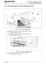
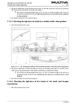
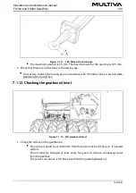
Figure. 7.1.2.1. - 171. Wheel bolts of the transport wheels

1.   Check that all the M20 x 1.5 wheel bolts (1) of the transport wheels are tight.

Each transport wheel has 6 bolts. There are 10 transport wheels on the FX300 and

13 on the FX400.

Tighten the bolts, if needed. If the gap between the tyres is narrow, tighten the

bolts from the next gap by using a ratchet and a handle. 

The bolts have been factory-installed with a locking compound. 

Operation and maintenance manual

1.00

FX300 and FX400 SeedPilot

137 (208)

Содержание FX300 SeedPilot

Страница 1: ...Operation and maintenance manual Seed drill FX300 and FX400 SeedPilot Translation of the original manual EN...

Страница 2: ...2 SeedPilot and SeedPilot ISOBUS control system 4 2 1 Control system components 4 2 1 1 Control unit 4 2 1 2 Seeding position sensor 4 2 1 3 Speed sensor 4 2 1 4 Shaft rotation guards 4 2 1 5 Hopper...

Страница 3: ...machine with a turnbuckle 5 3 4 Adjusting the lengthwise level of the machine with a drawbar cylinder 5 3 5 Using the machine lifting circuit ball valve 5 3 6 Ensuring the steerability of the tractor...

Страница 4: ...er target rate machine with gearbox 6 8 5 Seed calibration test in a machine without a gearbox 6 8 6 Seed calibration test in a machine with a gearbox on the seed side or a dual gearbox 6 8 7 Calibrat...

Страница 5: ...tiliser target rate 7 2 Lubrication 7 2 1 Quick instructions lubrication 7 2 2 Lubricating the transmission chains 7 2 2 1 Lubricating the chains in a machine without a gearbox 7 2 2 2 Lubricating the...

Страница 6: ...ulters 7 9 1 Replacing a coulter 7 9 1 1 Dismounting a coulter 7 9 1 2 Installing a coulter 7 9 2 Replacing a coulter disc 7 9 2 1 Detaching a disc 7 9 2 2 Installing the disc 7 9 3 Replacing a coulte...

Страница 7: ...207 208 9 5 Connection socket in accordance with SFS 2473 9 6 Calculating the stability of the tractor seed drill combination Operation and maintenance manual 1 00 FX300 and FX400 SeedPilot 7 208...

Страница 8: ...are designed for this particular seed drill The manufacturer bears no responsibility for spare parts and accessories provided by other suppliers Using them in certain circumstances may weaken the mac...

Страница 9: ...om transport wheels Adjustable hopper dividers Covering wheel scrapers Coulter pressure adjustment indicator Controller type choose one of the following Lykketronic area counter Comfort controller See...

Страница 10: ...ntrol systems Available on a machine with a gearbox on the fertiliser and seed side Dispersing axle Front platform Front levelling board Available with a wheel packer Middle markers Available with Com...

Страница 11: ...s or this operating manual Note that inappropriate use of fertilisers and plant protecting agents may cause damage to plants humans animals water system or soil Follow the instructions provided by the...

Страница 12: ...that all operators of the machine acquaint themselves with the machine s operating and safety instructions 1 5 Tightening torques The table below shows the tightening torques of steel screws and nuts...

Страница 13: ...period 5 Warranty does not cover damage caused by incorrect operation or maintenance in violation of the operating manual excessive loading or normal wear loss of income downtime other consequential...

Страница 14: ...hazard when the accessories are being adjusted Before adjusting the accessories make sure that the tractor is turned o the key is removed from the ignition and the parking brake is engaged Be careful...

Страница 15: ...eir ball valves are closed Prior to performing the calibration test ensure that the tractor parking brake is engaged the STOP ALL function is on in the SeedPilot or SeedPilot ISOBUS control system the...

Страница 16: ...oses and electric wires that the tractor is turned o and the key is removed from the ignition DANGER Never adjust or clean a moving seed drill DANGER Never stay on top of the seed drill or within its...

Страница 17: ...lectric equipment CAUTION Before servicing ensure that the machine lifting ball valve is closed and the cylinders are equipped with stoppers CAUTION Use original spare parts of the machine whenever se...

Страница 18: ...tion 1 pc 4 Hydraulic connection of the adjustment of the front levelling board position 1 pc 5 Danger of crushing when connecting and disconnecting the seed drill Minimum safe distance 5 m 1 pc 6 Cut...

Страница 19: ...d drill Table 3 3 7 Right side labels of the seed drill 1 Falling hazard do not climb on top of the wheel 2 pcs at both ends of the working platform 2 Falling hazard 2 pcs at both ends of the working...

Страница 20: ...eft side of the seed drill Table 3 3 8 Warning labels on the left side of the seed drill 1 Crushing and impact hazard when lifting and lowering the middle markers 2 pcs on both middle markers 2 Crushi...

Страница 21: ...ines without a gearbox or a gearbox on the seed side 2 Seeding quantities 1 pc underneath the transmission cover 3 Adjustment scale 0 pcs on a machine without a gearbox 1 pc on a machine with a gearbo...

Страница 22: ...d lights of the rear of the seed drill 1 Crushing and impact hazard when lifting and lowering the rear markers 2 pcs 2 Rear lights 2 pcs 3 Re ectors 2 pcs 4 Warning tape 2 pcs 5 Plate slow vehicle 1 p...

Страница 23: ...w of the seed drill Table 3 3 12 Overhead view of the seed drill 1 Label indicating the location of the operation manual 1 pc 2 Warning tape 2 pcs on both markers of the machine 3 Label indicating the...

Страница 24: ...e 3 3 13 Labels on the front platform 1 Falling hazard 2 pcs on both ends of the front platform 3 4 Using the middle marker ball valves Figure 3 4 10 Middle marker ball valves Operation and maintenanc...

Страница 25: ...servicing The ball valve of the middle marker is closed when the handle 1 is perpendicular to the hydraulic hose A Open the 2 middle marker ball valves 4 when putting the machine in its working positi...

Страница 26: ...instructions describe the Lykketronic area counter and the SeedPilot and SeedPilot ISOBUS control systems 4 1 Lykketronic area counter 4 1 1 Counter components Figure 4 1 1 11 Area counter components...

Страница 27: ...ansmission The 3 metre cable 4 is connected to the machine frame The 5 metre connecting cable 3 is connected to the 3 metre cable 4 1 2 Counter buttons and display Figure 4 1 2 13 Area counter 1 Displ...

Страница 28: ...ash Press the C key repeatedly until the value is 0 4 1 3 2 Setting the value of advance The advance is set to 150 0 cm The value is entered in centimetres 1 Press the C key repeatedly until the adva...

Страница 29: ...during use the battery voltage starts to decrease and the batteries should be changed The device switches o automatically if it has bot received a pulse from the sensor for 0 5 1 5 hours or if no key...

Страница 30: ...2 1 2 Seeding position sensor Figure 4 2 1 2 15 Seeding position sensor The seeding position sensor 1 recognises when the machine is in the transport or seeding position The seeding position sensor wo...

Страница 31: ...shaft rotation guards An inductive sensor 1 4 and sensor wheel 2 3 are located on the left edge of the feeder unit on both the fertiliser and seed sides viewed from the back of the machine The sensor...

Страница 32: ...of hopper level sensors to 4 The hopper level sensors are capacitive sensors If the seed or fertiliser level in the hopper is too low an alarm is triggered in the controller 4 2 1 6 Tramline clutches...

Страница 33: ...generated when a row is not seeded 4 2 1 7 Tramline extensions Figure 4 2 1 7 21 Tramline extensions The tramline clutch comes standard with one notched feeder roller see section 4 2 1 6 Tramline clu...

Страница 34: ...e of the fertiliser feed rate In machines without a gearbox or with one gearbox on the seed side the linear actuator is found in the feeder unit gure on the left In machines with a dual gearbox i e a...

Страница 35: ...e push button 1 is located under the transmission cover The button light is blinking when the linear actuator seeks the correct position during the fertiliser calibration test when a machine is equipp...

Страница 36: ...camera 1 is located at the rear of the machine A video image appears in the user interface when backing up the machine The reversing camera is optional 4 2 1 13 Work lights Figure 4 2 1 13 27 Work li...

Страница 37: ...4 2 2 SeedPilot control panel 4 2 2 1 SeedPilot control panel buttons Figure 4 2 2 1 28 Display 1 Power button 4 2 2 2 SeedPilot control panel settings Figure 4 2 2 2 29 Overview screen Bring up the m...

Страница 38: ...omma as the decimal separator in the Decimal point format 4 4 2 2 4 SeedPilot control panel environment setup Figure 4 2 2 4 31 Environment setup 1 Press the USER button 1 2 Press the ENVIRONMENT butt...

Страница 39: ...the Date format menu 3 Select the desired time format in the Time format menu 4 Set the current date in the Current date menu 5 Set the current time in the Current time menu 6 4 2 3 User interface Fi...

Страница 40: ...e end of the eld if for example a sensor is malfunctioning 4 Settings Figure 4 2 3 34 Drive screen and seeding settings automatic Figure 4 2 3 35 Drive screen and seeding settings manual Operation and...

Страница 41: ...Figure 4 2 3 36 Seeding settings Figure 4 2 3 37 Transport screen Operation and maintenance manual 1 00 FX300 and FX400 SeedPilot 41 208...

Страница 42: ...Figure 4 2 3 38 Manual mode Figure 4 2 3 39 Basic settings Operation and maintenance manual FX300 and FX400 SeedPilot 1 00 42 208...

Страница 43: ...Figure 4 2 3 40 Sensor settings Figure 4 2 3 41 Alarm and accessory settings Operation and maintenance manual 1 00 FX300 and FX400 SeedPilot 43 208...

Страница 44: ...ettings 3 Tramline counter correction See section 6 3 7 Tramline counter correction 4 Switching of the middle marker side See section 6 3 5 Using the middle marker automation 5 STOP ALL See section 6...

Страница 45: ...rtiliser target rate data from the Task Controller 2 TC Task Controller The box is green when the Task Controller is on Only in the SeedPilot ISOBUS control system 3 Location based variable rate seed...

Страница 46: ...feeder roller for small seed 5 Driving speed and area Displays the machine speed km h and seeded area ha If the lift sensor shows that the machine is in the raised position an arrow on the screen ind...

Страница 47: ...se 7 Product calibration See sections 6 8 3 Calibration test with adjusting of fertiliser target rate basic model and 6 8 4 Calibration test with adjusting of fertiliser target rate machine with gearb...

Страница 48: ...ng 4 2 4 2 Transport drive Figure 4 2 4 2 46 Transport drive 1 Driving speed screen When speed data is received from the tractor Only with the SeedPilot ISOBUS control system 2 Return 3 STOP ALL Shuts...

Страница 49: ...t ISOBUS control system 2 Rear markers The rear markers are in use when activated 3 Return 4 Tramlines Tramlines are on when activated 5 Lift inhibit function When activated only the middle markers ar...

Страница 50: ...ning properly The circle is red when the fertiliser level in the hopper is too low 4 Feed rate fertiliser Displays the fertiliser feed rate 5 Seed screen The screen displays the seed feed rate and dat...

Страница 51: ...green bar in the bar gauge and as a percentage 4 2 4 4 Settings Figure 4 2 4 4 49 Basic settings 1 Return 2 Sensor calibration See section 7 10 1 Sensor calibration 3 Travel distance calibration See...

Страница 52: ...Shaft rotation guard small seed 3 Main chain gear Disabled The alarm is not activated 4 Shaft rotation guard seed 5 Tramline clutch guard seed Monitors that the tramline clutch rotates when tramline i...

Страница 53: ...7 Linear actuator alarm The alarm is triggered when the linear actuator fails to reach the desired position Operation and maintenance manual 1 00 FX300 and FX400 SeedPilot 53 208...

Страница 54: ...the wheel packer only when the machine is on a level surface Figure 5 1 1 51 Lifting the wheel packer 1 Place the wheel packer 1 to the centreline and to the front of the machine and attach the lifti...

Страница 55: ...gure 5 1 1 53 Hydraulic hoses and electrical wires 6 Open the fastening screw 3 of the tube mounts and remove the top 4 7 Draw the hydraulic hoses through the guide 1 and on both sides of the cylinder...

Страница 56: ...rill cylinder retract 10 Connect the hydraulic hoses 3 6 Connect the hydraulic hoses of the drawbar cylinder only when the drawbar cylinder is installed 11 Push the hoses back towards the drawbar to e...

Страница 57: ...55 Drawbar cylinder Number Component Quantity 1 Cotter 8x71 2 pcs 2 Pin 45x110 2 pcs 3 Washer M45 4 pcs 1 Replace the washer 3 and fasten the drawbar cylinder to the seed drill with a mounting pin 2...

Страница 58: ...place with the cotter 3 3 Repeat steps 1 2 for the second turnbuckle of the cylinder 5 1 4 Mounting the front levelling board The front levelling board is an accessory Using the front levelling board...

Страница 59: ...evelling board weighs 250 kg 2 Follow the mounting instructions for the FX300 or FX400 Mounting the front levelling board on a FX300 Figure 5 1 4 58 Mounting the front levelling board on a FX300 Numbe...

Страница 60: ...t Quantity 1 Hex screw M24x60 7 pcs 2 Washer M24 26 pcs 3 Locking nut M24 13 pcs 4 Hex screw M24x75 3 pcs 5 Shim 5 pcs 6 Hex screw M24x120 3 pcs 1 Raise the front levelling board using lifting slings...

Страница 61: ...cs 1 Mount the markers on the shaft of the markers on both sides of the seed drill by using components 1 6 Tighten the bolts of the markers so that there is no clearance 5 1 6 Removing the transport s...

Страница 62: ...both sides of the seed drill 5 1 7 Mounting the scraper The scraper is an accessory Figure 5 1 7 62 Mounting the scraper Number Component Quantity 1 Hex screw M16X50 6 pcs 2 Washer M16 12 pcs 3 Scrape...

Страница 63: ...e rear harrow The rear harrow is an accessory DANGER The mounting of the rear harrow requires two people DANGER Use a hoisting accessory when mounting the rear harrow Figure 5 1 8 63 Mounting the rear...

Страница 64: ...seed drill with shackles 1 3 Figure 5 1 8 65 Lifting the rear harrow 3 Fasten a lifting sling 1 around the tube 2 DANGER Ensure that the capacity of the lifting sling and the lifting device is su cien...

Страница 65: ...etween the clamps 6 5 Attach the rear harrow tube to the rear harrow arms by fastening the clamp with washers 1 a hex screw 2 and a locking nut 5 Tighten the bolts of the rear harrow so that there is...

Страница 66: ...pacity of the lifting sling and the lifting device is su cient The rear markers weigh 75 kg 2 Lift the rear marker from its frame 2 using a lifting sling 1 and set the frame so that the rear marker ar...

Страница 67: ...x70 4 pcs 4 Hex screw M20x70 2 pcs 5 Washer M20 4 pcs 6 Washer M20 4 pcs 7 Locking nut M20 2 pcs 3 Attach the rear markers to the front levelling board actuating arms with washers 2 5 6 hex screws 3 4...

Страница 68: ...24 4 pcs 3 Linchpin 4 pcs 5 Take the cylinder from the working platform and mount it on the actuating arm with pins 1 and washers 2 6 Lock the mounting pin in place with the linchpin 3 7 Repeat steps...

Страница 69: ...Washer M8 8 pcs 4 U bolt 4 pcs For transport the rear railing 1 of the working platform has been turned inward 1 Open the bolts of the rear railing of the working platform 2 Turn the railing outward...

Страница 70: ...3 U bolt 2 pcs 4 Attach the end railing to the working platform with washers 2 U bolt 3 and locking nuts 1 5 Repeat step 4 for the second attachment point 5 2 Commissioning 5 2 1 Installing the Lykket...

Страница 71: ...the cabin from the fastening holes 2 by two fastening screws Attach the display in a location where view is not obstructed but where the display is easily viewable by turning one s glance while drivi...

Страница 72: ...l not be seeded but a tramline will be made Tramline automation settings are made on the Seeding settings The width 5 of the seed drill is displayed on the screen The number of seed drill widths appli...

Страница 73: ...ame as the width of the seed drill 1 In this case there are 8 passes thus making the application width 4 24 m When asymmetric tramline automation is selected tramlines 2 3 are made on passes 4 and 5 O...

Страница 74: ...Figure 5 2 3 1 77 Symmetric tramlines When symmetric tramline automation is selected tramlines 1 2 are made on the fth pass Operation and maintenance manual FX300 and FX400 SeedPilot 1 00 74 208...

Страница 75: ...marker delay when turned on and 5 is the rear marker delay when turned o The delay when turned on is the delay in seconds from when the machine has been lowered to when the marker solenoid opens and t...

Страница 76: ...connecting the seed drill to the tractor 1 If the machine is equipped with a wheel packer adjust the length of the wheel packer drawbar in accordance with section 5 3 1 Adjusting the length of the bo...

Страница 77: ...ct hydraulic hoses in pairs so that the directions of ow are correct The hydraulic hoses are marked with colour coded collars Check the tractor manual to ensure the hydraulic connections are suitable...

Страница 78: ...fting Figure 5 3 81 SeedPilot ISOBUS controller power cable 7 If the machine is equipped with a SeedPilot ISOBUS control system plug the controller power cable 1 into the ISOBUS connector on IBBC trac...

Страница 79: ...ccordance with the instructions in section 5 3 6 Ensuring the steerability of the tractor 12 When driving on a eld for the rst time set the middle markers in accordance with the instructions given in...

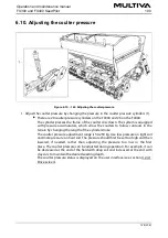
Страница 80: ...he ground support 2 Move the ground support up or down by the lever 1 3 Lock the ground support in the mounting hole Attach the mounting pin and the cotter The upper mounting hole 2 locks the ground s...

Страница 81: ...by the handle 1 and check visually that the machine is straight 5 When the machine is straight turn the plate downward to engage the lock 5 3 4 Adjusting the lengthwise level of the machine with a dr...

Страница 82: ...ve Figure 5 3 5 89 Lifting circuit ball valves DANGER Close the lifting circuit ball valve 2 before starting out and performing maintenance The ball valve of the lifting circuit is closed when the han...

Страница 83: ...seeding depth 5 3 7 Adjusting the middle markers Figure 5 3 7 90 Adjusting the middle markers 1 Loosen the two screws 1 2 Adjust the width of the marker axle 3 3 Adjust the toe in 2 by rotating the d...

Страница 84: ...instructions in section 5 3 5 Using the machine lifting circuit ball valve 6 Check the tyre pressure in accordance with section 7 1 3 Checking tyre pressure 7 Ensure that the machine is clean If neces...

Страница 85: ...working position 1 Open the machine lifting circuit ball valve in accordance with the instructions in section 5 3 5 Using the machine lifting circuit ball valve 2 If the machine is equipped with a See...

Страница 86: ...rned on before starting and running a calibration test DANGER Turning on the STOP ALL function alone is not su cient the middle marker ball valves must also be closed See the instructions in section3...

Страница 87: ...to select the desired calibration test result The corresponding number is displayed in the drive screen 3 The calibration test result is entered manually by pressing the desired number value 2 Instru...

Страница 88: ...ive screen Press the 10 button 2 to increase the fertiliser target rate by the preset step Press the 10 button 6 to decrease the fertiliser target rate by the preset step In this case the set step amo...

Страница 89: ...percentage of the fertiliser target rate In this case calibration preset A is 108 and calibration preset B is 77 of the fertiliser target rate of 325 kg ha Press the 100 button 3 to change the fertil...

Страница 90: ...the machine is raised when coming to a headland 6 3 5 Using the middle marker automation Figure 6 3 5 101 Selecting the middle markers and driving mode 1 Press the MIDDLE MARKER button 3 on the Seedin...

Страница 91: ...ITCHING OF THE MIDDLE MARKER SIDE button 1 The yellow arrow 2 shows the direction of the next turn left right 6 3 6 Middle markers manual control and forcing operation Figure 6 3 6 103 Selecting addit...

Страница 92: ...rs from lowering in both automatic and manual mode even if 4 and 2 are on The buttons are yellow when activated 6 3 7 Tramline counter correction Figure 6 3 7 105 Tramline counter correction The traml...

Страница 93: ...nsor is in use when the box is checked 6 3 9 Area counter use Figure 6 3 9 107 Area counters Field speci c counters display each eld s seeded area 3 e ective work time 2 and the total quantity of seed...

Страница 94: ...2 Press OK 2 to accept the reset 6 3 10 Manual mode selection The manual mode is selected when using the tramline and markers manually Figure 6 3 10 109 Manual mode selection 1 Press MANUAL 1 The but...

Страница 95: ...he e ective roller length with screw type control wheels Fine tuning is done from the machine s transmission by adjusting the gearbox control lever In seed drills without a gearbox the rough tuning of...

Страница 96: ...located under the seed drill s transmission cover The seeding tables for di erent varieties are presented below Figure 6 5 111 Seeding table for machines with standard equipment Figure 6 5 112 Seedin...

Страница 97: ...Figure 6 5 113 Seeding table seed gearbox 1 Figure 6 5 114 Seeding table seed gearbox 2 Operation and maintenance manual 1 00 FX300 and FX400 SeedPilot 97 208...

Страница 98: ...Figure 6 5 115 Seeding table seed gearbox 3 Figure 6 5 116 Seeding table seed and fertiliser gearbox 1 Operation and maintenance manual FX300 and FX400 SeedPilot 1 00 98 208...

Страница 99: ...nd fertiliser gearbox 3 6 6 Preparations preceding hopper lling 6 6 1 Preparations preceding hopper lling in a machine without a gearbox 1 Ensure that the stability of the tractor seed drill combinati...

Страница 100: ...ing the stability of the tractor seed drill combination 2 Ensure that the hopper is empty clean and dry If needed clean the hopper in accordance with the instructions in section 7 3 1 Cleaning the hop...

Страница 101: ...te position in the feeder units of the small seed hopper 6 6 4 Adjusting the hopper divider Figure 6 6 4 119 Adjusting the hopper divider DANGER Before adjusting the divider ensure that the hoppers ar...

Страница 102: ...di erent positions of the divider on the FX400 FX400 Seed L Fertiliser L Total L 1 1 500 3 300 4 800 2 1 700 3 100 4 800 3 1 850 2 950 4 800 4 2 050 2 750 4 800 5 2 200 2 600 4 800 6 2 350 2 450 4 800...

Страница 103: ...s The control wheel 1 is for seeds and control wheel 2 is for fertiliser If the machine is equipped with adjusting of fertiliser target rate there is no fertiliser control wheel The seed quantity incr...

Страница 104: ...ith the chain gears and the ne adjustment by adjusting the width of the roller Figure 6 6 6 122 Changing the chain gears and chain 1 Loosen the tensioning wheel 1 2 Remove the cotter 2 from the chain...

Страница 105: ...ding quantity increases when the value of the adjustment scale increases and vice versa Adjust the width of the feeder roller in accordance with section 6 6 5 Adjusting the width of the feeder roller...

Страница 106: ...ol lever is adjusted from the working platform 6 6 9 Adjusting the shut o plate position Figure 6 6 9 126 Adjusting the shut o plate position 1 Adjust the position of the shut o plates 1 of the feeder...

Страница 107: ...side of the small seed hopper The seeding tables are provided in section 6 5 Seeding quantities The main scale of seeding quantity is on the control wheel lock 2 and the secondary scale on the contro...

Страница 108: ...tion in the feeder units of the small seed hopper 1 Change the position of the control lever 1 on the notch scale Figure 6 6 11 130 Bottom ap positions in the feeder units of the small seed hopper Whe...

Страница 109: ...ryegrass the shut o plate must be closed two notches When seeding clover the shut o plate must be closed three notches All shut o plates should be in the same position 6 7 Filling the hoppers DANGER...

Страница 110: ...n top of the seed drill or inside the hoppers when the hoppers are being lled DANGER Avoid breathing seed dressing dust and fertiliser dust The seed dressing causes a serious health risk DANGER Read t...

Страница 111: ...rtiliser and seeds the vibration may cause arching in the hoppers In the autumn or after rain the fertiliser may absorb humidity in the feeders changing fertiliser uidity For this reason it is good to...

Страница 112: ...ibration test crank 3 to the calibration test axle Turn the crank until an even ow of fertiliser comes out of all feeders Empty the calibration trays 6 Rotate the axle counterclockwise by 1 round per...

Страница 113: ...d their lock 6 is turned to the side 4 Remove the cotter 4 of the seed side from the feed shaft chain gear If the machine is equipped with a small seed hopper remove the cotter pin 2 of the small seed...

Страница 114: ...close the middle marker shut o valves according to the instructions in section 3 4 Using the middle marker ball valves The linear actuator only moves when the feeder shaft is rotating to prevent the f...

Страница 115: ...he memory slot 2 for saving data Instructions on the calibration test memory slots are found in section 6 3 2 Calibration test result memory slots 8 Press START 1 Product calibration Figure 6 8 3 140...

Страница 116: ...he value Figure 6 8 3 142 Calibration test crank On the left a machine without a gearbox and on the right a machine equipped with a gearbox 2 Attach the calibration test crank 1 to the calibration tes...

Страница 117: ...The number of calibration test crank turns 2 are displayed on the screen If the linear actuator is already in the correct position the red box will not appear In this case move directly to step 4 3 Em...

Страница 118: ...tuator works only when seed shafts rotate until the feeder shaft begins rotating when starting the rst pass 9 Insert the cotter pins 10 Turn the crank to bring the calibration trays to the seeding pos...

Страница 119: ...libration test with adjusting of fertiliser target rate on a machine with a dual gearbox 2 Align the calibration trays 4 with the fertiliser side feeder shaft by turning the crank 1 to position 1B The...

Страница 120: ...for saving data Instructions on the calibration test memory slots are found in section 6 3 2 Calibration test result memory slots 8 Press START 1 Figure 6 8 4 150 Linear actuator The linear actuator 3...

Страница 121: ...tion test crank turns 1 will appear on the user interface page Figure 6 8 4 153 Push button Only in the SeedPilot ISOBUS control system When 5 turns have been made the light in the push button 1 stays...

Страница 122: ...to the seeding position 8 Put the transmission cover back in place 6 8 5 Seed calibration test in a machine without a gearbox DANGER If the machine is equipped with a SeedPilot or SeedPilot ISOBUS co...

Страница 123: ...econd using the calibration test crank An area of 100 m is obtained by turning the crank 22 rounds on the FX300 and 16 5 rounds on the FX400 7 Pull out the calibration trays and weigh the quantities t...

Страница 124: ...ration trays 5 with the seed side feeder shaft by turning the crank 1 to position 1A The crank position 1B is for the fertiliser side and the centre position is for seeding 3 Check that the calibratio...

Страница 125: ...achine is equipped with a SeedPilot or SeedPilot ISOBUS control system switch on the STOP ALL function in accordance with section 6 3 1 Using the STOP ALL function DANGER Shut o the tractor remove the...

Страница 126: ...rea of 100 m is obtained by turning the crank 22 rounds on the FX300 and 16 5 rounds on the FX400 7 Pull out the calibration trays of the small seed hopper and weigh the quantities they now contain Th...

Страница 127: ...lever is down the seeding depth is at maximum i e 8 cm When the lever is up the seeding depth is 0 cm The height adjustment is indexed in approx 0 5 cm increments 2 Repeat step 1 for all coulters Fig...

Страница 128: ...of the cylinder stroke The coulter pressure adjustment range is 50 250 kg Use less pressure on light soil and more pressure on hard soil The pressure should rst be set too high and then lowered if ne...

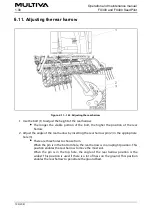
Страница 129: ...2 in the appropriate hole 3 There are three holes to choose from When the pin is in the bottom hole the rear harrow is in an upright position This position enables the rear harrow to move the most soi...

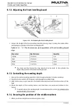
Страница 130: ...he higher the position of the front levelling board 6 13 Controlling the seeding depth 1 Drive at the normal seeding speed 8 12 km h approximately 10 metres and stop 2 Stop the tractor switch o the po...

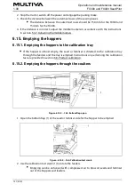
Страница 131: ...r is almost empty the seed or fertiliser is directed to the calibration tray through the feeders and the tray is emptied Instructions on performing the calibration test are provided in section 6 8 Pro...

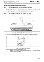
Страница 132: ...ibration test of small seed hopper 6 16 2 Emptying the small seed hopper through pipes Figure 6 16 2 167 Bottom ap of the small seed hopper open 1 Open the small seed hopper bottom ap by turning the c...

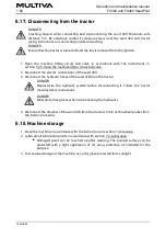
Страница 133: ...m the tractor DANGER Depressurise the hydraulic system before disconnecting it Follow the tractor manufacturer s instructions DANGER Wear protective gloves when disconnecting the hydraulics 4 Disconne...

Страница 134: ...ifting cylinders 1 3 The stoppers are placed on the outermost cylinders 1 3 5 Depressurise the coulter pressure circuit by holding the tractor valve open for approx 10 seconds The coulter pressure sta...

Страница 135: ...ifting cylinder 2 onto which the stoppers are placed The FX400 has 3 lifting cylinders 1 3 The stoppers are placed on the outermost cylinders 1 3 Place a stand or other suitable support under the mach...

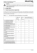
Страница 136: ...res 2 Every 50 hectares 3 Every 500 hectares or once per operating season 7 1 2 Checking bolt tightness X X 7 1 3 Checking tyre pressure X X 7 1 4 Checking the bearing clearance of the wheel packer hu...

Страница 137: ...1 of the transport wheels are tight Each transport wheel has 6 bolts There are 10 transport wheels on the FX300 and 13 on the FX400 Tighten the bolts if needed If the gap between the tyres is narrow...

Страница 138: ...ng gear 1 Check that all the 24 M16 ange bearing bolts 1 of the transport wheel assembly are tight Each bearing has four bolts There are six bearings Tighten the bolts if needed If the gap between the...

Страница 139: ...el packer bar 1 2 Detach the wheel packer bar by lifting it Figure 7 1 2 3 174 Wheel bolts of the wheel packer 3 Check that all the 20 M18 wheel bolts 1 of the wheel packer are tight Tighten the bolts...

Страница 140: ...to torque 300 Nm Figure 7 1 2 4 176 Bolts of the coulter covering wheel and depth adjustment 2 Check that the 2 M16 3 and M20 4 bolts on all the coulter covering wheels are tight Tighten the bolts if...

Страница 141: ...ng platform are tight Tighten the bolts if needed 2 Check that the 4 M16 bolts 1 near the lifting cylinder are tight Tighten the bolts if needed Figure 7 1 2 5 178 Working platform U bolts 3 Check tha...

Страница 142: ...f the wheel packer available as an accessory is 3 0 bar 7 1 4 Checking the bearing clearance of the wheel packer hubs Figure 7 1 4 180 Checking the bearing clearance of the wheel packer hubs 1 Insert...

Страница 143: ...own and lifting it up with your nger The maximum allowed chain de ection A is 10 mm If needed tighten the chains in accordance with section 7 5 1 Tightening the chains in a machine without a gearbox 3...

Страница 144: ...ver Figure 7 1 5 3 183 Checking the tightness of the transmission chains in a machine with a dual gearbox 2 Check the de ection of the transmission chain 2 fertiliser side chain 3 and the seed side ch...

Страница 145: ...If needed tighten the chains in accordance with section 7 5 4 Tightening the transmission chains of the small seed hopper 3 Put the transmission cover back in place 7 1 6 Checking the tightness of th...

Страница 146: ...drive clutch The clutch should be inspected once per year seeding season Figure 7 1 7 187 Inspecting the clutch 1 Check the clearance of the exible coupling element of the clutch 1 Check the clearance...

Страница 147: ...After adjusting tighten the locking nut 1 7 1 9 Checking the condition of hydraulics 1 Check the tightness of the hydraulic system 2 If needed tighten the joints 3 Make sure that the hoses are intact...

Страница 148: ...eplacing the towing eye 7 1 12 Checking the gearbox oil level Figure 7 1 12 190 Gearbox oil level 1 Check the oil level in the gearbox es The oil level should be at 40 45 mm from the bottom of the ll...

Страница 149: ...s not rotate clean the discs if needed in accordance with section 7 3 4 Cleaning the coulter discs If the disc still does not rotate replace the disc if needed in accordance with section 7 9 2 Replaci...

Страница 150: ...ent moves even when the seed shafts do not rotate 7 2 Lubrication After the commissioning of the machine all lubrication points should be lubricated after the rst 10 hectares The coulter discs are equ...

Страница 151: ...xle mounting X 2 7 2 5 Lubricating wheel axle bearings X 6 7 2 6 Lubricating the lifting cylinder X FX300 2 FX400 6 7 2 7 Lubricating the towing eye X 7 2 8 Lubricating the middle marker cylinders X 4...

Страница 152: ...cs and not only in the reel 3 Put the transmission cover back in place 7 2 2 2 Lubricating the chains in a machine with a gearbox on the seed side 1 Raise the transmission cover Figure 7 2 2 2 194 Lub...

Страница 153: ...between the chain discs and not only in the reel 3 Put the transmission cover back in place 7 2 2 4 Lubricating the small seed hopper transmission chains 1 Raise the transmission cover Figure 7 2 2 4...

Страница 154: ...re that oil also ows between the chain discs and not only in the reel 3 Reattach the housing cover and fasten the two fastening bolts of the cover Always use new locknuts to fasten 7 2 3 2 Lubricating...

Страница 155: ...g 3 Reattach the housing cover and fasten the two fastening bolts of the cover Use new locknuts to fasten 7 2 4 Lubricating the rear axle mounting Figure 7 2 4 200 Rear axle mounting 1 Lubricate the t...

Страница 156: ...Lubricating the li ing cylinder Figure 7 2 6 202 Lifting cylinder 1 Lubricate the lifting cylinder s The FX300 has 1 lifting cylinder 2 and the FX400 has 3 lifting cylinders 1 3 There is a grease nip...

Страница 157: ...lubricant on the towing eye 7 2 8 Lubricating the middle marker cylinders Figure 7 2 8 204 Middle marker cylinders 1 Lubricate the 2 middle marker cylinders 1 There is a grease nipple at the top and b...

Страница 158: ...ders 1 Lubricate the 2 rear marker cylinders 1 There is 1 grease nipple 2 in the bearing housing of both cylinders 7 2 10 Lubricating the wheel packer pins and wheel hubs Figure 7 2 10 206 Wheel packe...

Страница 159: ...n both pins of the wheel packer bar Figure 7 2 10 207 Detaching the wheel packer bar 3 Detach the two cotters 2 of the wheel packer bar 1 4 Detach the wheel packer bar by lifting it Figure 7 2 10 208...

Страница 160: ...velling board cylinders 1 There is one lubricating nipple at the top of both cylinders 7 2 12 Lubricating the drawbar cylinder Figure 7 2 12 210 Drawbar cylinder 1 Lubricate the drawbar cylinder 1 The...

Страница 161: ...e gloves when cleaning the hoppers Clean the seed hopper when the variety to be seeded changes and at the end of the seeding season Clean the fertiliser hopper at the end of the seeding season Figure...

Страница 162: ...d seed hopper 3 4 with a detergent and warm water 6 If needed clean the hoppers with power wash CAUTION Do not allow water to enter electrical instruments 7 Dry the hoppers with pressurised air 8 Clos...

Страница 163: ...AUTION Do not allow water to enter electrical instruments 5 Dry the hopper with pressurised air 6 Close the bottom ap of the feeder unit 7 3 3 Cleaning the paint surface Wear protective goggles and pr...

Страница 164: ...ves when cleaning the discs of the coulters Figure 7 3 4 216 Discs of the coulters 1 Clean the discs 1 of the coulters with a power washer Clean the clearance between the scraper and covering wheel as...

Страница 165: ...l seed hopper feeder units Wear protective goggles and protective gloves when cleaning the feeder Clean the feeder units at the end of the seeding season Figure 7 3 6 218 Feeder roller 1 If there is s...

Страница 166: ...e wheels DANGER Ensure that the seed drill is properly in place and that the machine is in the transport position Ensure that the seed drill cannot move in any direction DANGER The wheel assembly dism...

Страница 167: ...e cylinders on the working platform Figure 7 4 1 221 Dismounting the rear harrow 3 If the machine is equipped with a rear harrow dismount the rear harrow by removing the bolts 2 washers 3 4 and nuts 5...

Страница 168: ...ry when dismounting the rear harrow Tie a lifting sling 1 around the tube 2 Figure 7 4 1 223 Transport supports 4 Install the transport supports 2 on both sides of the seed drill with M20x50 bolts 1 O...

Страница 169: ...ween the middle and the outermost wheel assembly to prevent the middle wheel assembly from falling Ensure that the bolts do not penetrate the back of the plate 2 3 If you are dismounting the left hand...

Страница 170: ...ution when the wheel assembly comes loose 7 4 2 Disassembling a wheel assembly Figure 7 4 2 227 Detaching a ange bearing 1 Open the locking screw 1 2 Remove the ange bearing 2 from the axle Use an ext...

Страница 171: ...should be dismounted from the side of the centre tyre bolts in the pack 7 4 3 Mounting a wheel assembly 1 Clean the surfaces before installing a wheel assembly 2 Clean the threads of bolts Figure 7 4...

Страница 172: ...230 Nm Use new locking nuts 2 Remove the transport supports 3 If necessary mount the scraper in accordance with section 5 1 7 Mounting the scraper the rear harrow in accordance with section 5 1 8 Moun...

Страница 173: ...eel to the right 5 Tighten the tensioning wheel 6 Tighten the fertiliser side chain by pushing the chain gear 3 down 7 Tighten the chain gear nut 3 8 Check the chains for de ection The de ection shoul...

Страница 174: ...arbox 2 Loosen the gearbox chain 3 by loosening the nut of the chain gears 1 5 3 Loosen the fertiliser side chain 2 by loosening the nut of the chain gear 6 4 Tighten the seed side chain 4 by pushing...

Страница 175: ...d Tighten the 3 bolts 2 of the bearing housing 6 Tighten the chain 6 by moving the casing vertically and the chain 4 by moving the casing horizontally 7 Tighten the three casing bolts 5 and the three...

Страница 176: ...ut by turning the wheel simultaneously until light resistance is felt in the bearing 1 5 Loosen the nut until the closure pin ts into the next slot where the bearing is rotating freely 6 Lock the pin...

Страница 177: ...chain 2 Open the mounting nut 1 located at the end of the chain guide 3 Tighten the wheel drive chain 2 by moving the guide towards the transmission axle 4 Tighten the mounting nut 1 of the chain gui...

Страница 178: ...ng screw 2 in the clutch body 2 Separate the components of the clutch 1 by pulling the clutch on the axle towards the wheel drive mechanism 3 Detach the exible coupling element 3 of the clutch 7 7 2 2...

Страница 179: ...ew 2 7 8 Towing eye 7 8 1 Replacing the towing eye 7 8 1 1 Detaching the towing eye Figure 7 8 1 1 242 Towing eye 1 Remove the 12 bolts 1 of the towing eye 2 Remove the towing eye 2 7 8 1 2 Installing...

Страница 180: ...DANGER Use a lifting aid to lift and move the coulter The coulter weighs more than 60 kg and has sharp edges Figure 7 9 1 1 244 Lowering coulters to the ground 1 Lower the coulters to the ground and...

Страница 181: ...of the coulter Do not remove the bolt right away but loosen all four bolts equally 5 Remove the bolts 1 installation plate 2 and 4 dampening rubbers 3 6 Move the coulter from its location 7 9 1 2 Inst...

Страница 182: ...to eliminate any gap between the mounting plates Use new locking nuts with a strength rating of 10 when mounting Figure 7 9 1 2 248 Mounting the coulter cylinder 6 Insert the bottom cylinder bolt M20...

Страница 183: ...ten the hose clamps 1 4 7 9 2 Replacing a coulter disc 7 9 2 1 Detaching a disc If necessary remove the coulter in accordance with the instructions in section 7 9 1 1 Dismounting a coulter Figure 7 9...

Страница 184: ...ousing 3 Use a bearing puller to remove the bearing housing 7 9 2 2 Installing the disc Install the bearing in accordance with section 7 9 3 2 Installing the bearing Figure 7 9 2 2 252 Installing the...

Страница 185: ...n the ve M12 x 1 5 mounting bolts 2 7 9 3 Replacing a coulter bearing 7 9 3 1 Detaching the bearing Remove the coulter disc in accordance with the instructions in section 7 9 2 1 Detaching a disc Figu...

Страница 186: ...ng 2 from the bearing housing 1 Pull the bearing using a clamp 7 9 3 2 Installing the bearing Figure 7 9 3 2 256 Installing the bearing 1 Clean the bearing housing 1 2 Install a new bearing 2 Install...

Страница 187: ...anged when the bearing is changed 7 9 4 Replacing a coulter covering wheel 7 9 4 1 Dismounting the covering wheel Figure 7 9 4 1 258 Dismounting the covering wheel 1 Remove the locknut 1 of the coveri...

Страница 188: ...M20 nut 2 Use new locking nuts when installing 7 9 5 Adjusting the scrapers 7 9 5 1 Adjusting the disc scraper DANGER Beware the sharp edges of the discs Figure 7 9 5 1 260 Disc scraper 1 Loosen the b...

Страница 189: ...s 1 2 of the cover wheel scraper 3 2 Adjust the distance between the scraper and the cover wheel by moving the scraper up or down The distance between the scraper and the cover wheel should be 2 3 mm...

Страница 190: ...he transport position The blue bar 1 moves along the scale 4 Press SET 2 7 10 2 Travel distance calibration 7 10 2 1 Travel distance calibration while driving The control system PIN code for travel di...

Страница 191: ...radar 1 only in SeedPilot ISOBUS the default value 5 and the new value obtained in calibration 6 are displayed on the page The system calibrates a new travel distance value based on the number 3 of pu...

Страница 192: ...must be between 16 and 24 Any values outside this range will not be saved The factory setting is 18 55 3 Press OK 2 Pressing the OK button closes the input eld and returns the screen to its start pag...

Страница 193: ...libration diagnostics data and linear actuator data I O calibration diagnostics data 1 and linear actuator data 2 are displayed in Settings Maintenance may request information from these pages Operati...

Страница 194: ...ng the actuator Remove the obstruction if necessary 2 Run the actuator in the direction opposite to what was running before the alarm Shaft not rotating even though the machine is running 1 Check for...

Страница 195: ...1 Make sure that the wires and connectors are intact 2 Rotate the shaft with a calibration test crank while tapping the clutch body If the suggested measures do not work contact authorised service Re...

Страница 196: ...1 The bottom ap position is incorrect 1 Check the position of the bottom ap in accordance with the instructions in section 6 6 8 Adjusting the bottom ap position or section 6 6 11 Adjusting the botto...

Страница 197: ...s closed 1 Open the machine lift ball valve in accordance with the instructions in section 5 3 5 Using the machine lifting circuit ball valve 2 The quick coupling is open 2 Check the connection of the...

Страница 198: ...ematics 3 Electrical schematics 4 SeedPilot component and connection list 5 Connection socket in accordance with SFS 2473 6 Calculating the stability of the tractor seed drill combination Operation an...

Страница 199: ...0303 L1010001 Multiva FORTE FX400 starting from serial number 000 090304 L1010001 meet the requirements of Machinery Directive 2006 42 EC with respect to the construction of machinery Furthermore the...

Страница 200: ...Hydraulic schematics FX300 and FX400 1 Hydraulic schematics FX300...

Страница 201: ...Hydraulic schematics FX300 and FX400 2...

Страница 202: ...Hydraulic schematics FX300 and FX400 3 Hydraulic schematics FX400...

Страница 203: ...Hydraulic schematics FX300 and FX400 4...

Страница 204: ...Electrical schematics FX300 and FX400 1 Electrical schematics...

Страница 205: ...Electrical schematics FX300 and FX400 2...

Страница 206: ...CAB CABLE CONNECOR B01 LEVEL SENSOR FERTILISER B02 LEVEL SENSOR SEED B06 AREA SENSORR B11 FERTILISER SHAFT ROTATION MONITOR B12 SEED SHAFT ROTATION MONITOR B13 SMALL SEED LEVEL SENSOR B14 SMALL SEED...

Страница 207: ...Connection socket according to SFS 2473 1 L Left turn signal 2 54G Free 3 31 Ground 4 R Right turn signal 5 58R Right rear light lic plate light 6 54 Brake light 7 58L Left rear light...

Страница 208: ...manual 2 See the implement manual 3 To be measured Figure 1 Calculating the stability of the tractor seed drill combination kg Tractor s dead weight 1 kg Front axle load of an empty tractor 1 kg Rear...

Отзывы: