Instruction manual (Translation of the original instructions)
CM150032EN - 16.06.15 - 05 (11.07.18)
49
/76
Self-moving Compact wheel loader, articulated frame, equipped with
multipurpose quick coupler, MULTIONE 6 Series
MultiOne SRL
8.3.5.2 Mechanical disconnection of the attachment with manual release system
WARNING
THERE ARE RESIDUALS RISKS N. 1, N. 2, N. 3 (SEE PAR. 3.2).
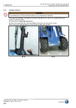
To disconnect the attachment with manual release system proceeds as follows:
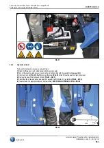
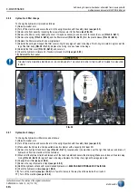
1) Lift and push back the two release levers (FIG. 24 - Ref. 3) from the quick coupler in order to disengage the two plugs.
2) Turn on the machine (see par. 8.3.2).
3) Move to the right the multifunction joystick in order to rotate forward the quick coupler of the machine. If necessary translate
backward a few cm.
4) Move “Forward” the multifunction joystick in order to lower the lifting arm and disassembly the attachment.
8.3.5.3 Mechanical disconnection of the attachment with hydraulic release system (option)
If the machine is supplied with hydraulic release system proceed as follows:
1) Turn on the machine (see par. 8.3.2).
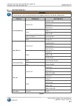
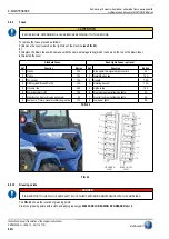
2) Press and hold the attachment release button
(TAB. 5 - Ref. 1) and at the same time activate the control of the flow of
couplings in “Forward” position (see par. 4.3.3).
3) Operating carefully decouple the coupler of the attachment.
4) Release the attachment release button
(TAB. 5 - Ref. 1) and replace the control of the flow of couplings in central position.
8.3.5.4 Use of the attachment
WARNING
TO USE THE ATTACHMENT PLEASE REFER TO THE INSTRUCTION ATTACHMENT MANUAL.
YOU MUST KEEP THE ATTACHMENT ASSEMBLED TO THE MACHINE MORE CLOSE AS POSSIBLE TO THE GROUND WHEN MOVING.
8.3.6
Turning off the machine
To turn off the machine proceed as follows:
1) Stop the machine without a steering.
2) Withdraw and lower the lifting arm and/or put the possible assembled attachment on the ground.
3) Set to the minimum the throttle, Pos. “Turtle”.
4) Insert the parking brake (see par. 8.3.7).
5) Release the pressure of the hydraulic system as described at (see par. 8.3.4.3).
6) Put the key in Pos. “0”.
7) Remove the key from the control panel and store it in a safe place.
8.3.7
Parking brake
To insert the parking brake proceed as follows:
6.3 model.
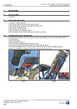
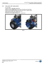
1) To insert the parking brake lift up and pull back the lever (FIG. 28 - Ref. 1).
2) To disengage the parking brake lift up and push forward the lever (FIG. 28 - Ref. 2).
6.3+ and 6.3S model
1) Put the starting key in Pos. ”1”.
2) Press the parking switch (FIG. 28 - Ref. 3), the light
turn on.
OPERATION -8


