background image


"Tank Control II" menu - Filling and operation 

Controlling external devices 


30252060-02-EN 

V2.20161017 

47 


4. 

To activate or deactivate the external device, press: 


  The status of the external device is displayed in the lower area of the screen. [

 45] 


  Press: 


  You have changed the mode of the external device. 


Viewing the configuration of the external devices 

You can display an overview of external device configuration.  


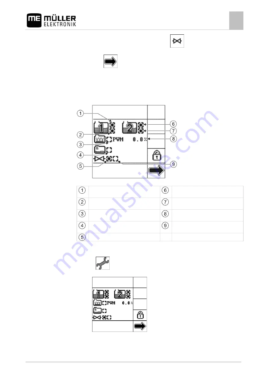
Overview of external devices 


Overflow sensor from manufacturer of tank 1, 
in this case: connected 


Overflow sensor from manufacturer of tank 2, 
in this case: connected 


Empty tank sensor from manufacturer of tank 
1, in this case: connected 


Empty tank sensor from manufacturer of tank 
2, in this case: not connected 


Agitator, in this case: with speed control and 
deactivated. 


Current agitator speed in percent. 


Filling pump, in this case: without speed 
control and deactivated. 


Ball valve is open, in this case: deactivated. 


Ball valve is shut, in this case: activated. 


1. 

Open the "Tank Control II" menu. 

2. 

Press: 


  The following screen will appear: 


3. 

Check that all the external devices are connected correctly and are activated or deactivated. 

9.5.3 

Procedure 

www.ROLTRONIK.pl

Содержание TANK-Control II

Страница 1: ...Operating Instructions TANK Control II Version V2 20161017 30252060 02 EN Read and follow these operating instructions Keep these operating instructions in a safe place for later reference w w w R O L...

Страница 2: ...60 02 EN As of software version 6 4 Original language German M ller Elektronik GmbH Co KG Franz Kleine Stra e 18 33154 Salzkotten Germany Phone 49 0 5258 9834 0 Fax 49 0 5258 9834 90 Email info muelle...

Страница 3: ...t of operating instructions 10 3 4 Layout of references 10 4 Installation instructions 12 4 1 Safety during installation 12 4 2 System requirements 12 4 3 Installing the sensor 12 4 3 1 Step 1 Drill h...

Страница 4: ...Control II menu on the terminal in the tractor cab 39 9 2 Calculating the volume of spray required 40 9 3 Filling the tank 41 9 4 Displaying the workable area 44 9 5 Controlling external devices 44 9...

Страница 5: ...use TANK Control II is intended exclusively for use in agriculture Intended use also means operating and maintaining the device in accordance with the manufacturer s specifications The manufacturer sh...

Страница 6: ...TICE This is a notice It warns that there is a risk involved in the next step 2 Step involving risk Alarm messages on the screen While working with the field sprayer an alarm message may appear on the...

Страница 7: ...ion of conformity This product has been manufactured in conformity with the following national and harmonised standards as specified in the current EMC Directive 2004 108 EC EN ISO 14982 Disposal When...

Страница 8: ...ontrol II do TANK Control II is a system which consists of a computer and a sensor The computer is an integral part of a control unit The sensor measures the actual fill level in the tank Summary of T...

Страница 9: ...er you can find all the information you need to identify the product Have these details ready when you contact Customer Services Information on the nameplate Client s item number If the product was ma...

Страница 10: ...information shown on the screen shots in these Operating Instructions may be different from that displayed on the terminal Layout of operating instructions The operating instructions explain step by s...

Страница 11: ...252060 02 EN V2 20161017 11 Example of a reference 10 References can be identified by their square brackets and an arrow The number following the arrow shows you on what page the section starts where...

Страница 12: ...sure that a second person is watching you and can help you in an emergency System requirements Software version 6 4 at least must be installed on the job computer for the field sprayer Installing the...

Страница 13: ...push the sensor tube and flange through the hole Using the flange 140 as a drilling template mark the screw positions on the tank 3 Drill 4 holes 8 5 mm diameter at the positions marked they will be...

Страница 14: ...asher A6 4 Base of tank Nut M6 1 Push a Viton gasket 25x6 onto the tube socket 2 Push the tube socket through the hole in the tank base from above 3 Push the second Viton gasket 25x6 onto the tube soc...

Страница 15: ...40 onto the sensor tube from below 2 Push the Viton gasket 140 onto the sensor tube from below 3 Push the float onto the sensor tube The 0 marking on the float must point upwards 4 Push washer 24 2x12...

Страница 16: ...the top of the tank 2 Screw the sensor tube into the tube socket on the tank base 3 Push a washer A8 4 large and a Viton gasket 25x8x3 onto each of the 4 hexagonal screws M8 4 Push the screws upwards...

Страница 17: ...at the corrugated tube does not deform if secured with cable ties Do not attach the corrugated tube to hydraulic lines Ensure that the corrugated tube is fixed to solid non vibrating parts Remove all...

Страница 18: ...t may move or be activated As a result people can be injured or property damaged Before pressing the keys or function keys Take all the steps described in the machine s Operating Instructions in order...

Страница 19: ...thing shown on the screen Elements of a screen Screen icon This icon shows which screen you are viewing Cursor Shows which field you have selected Main area Content of the screen displayed Function ic...

Страница 20: ...all the functions to load The following screen appears on the control unit The start screen displays three menus Service Sensors and Tank Control II These menus are all described in the next chapters...

Страница 21: ...rt screen you can also set the screen brightness and contrast Opening the Service menu To open the Service menu 1 Start the control unit The start screen appears 2 Select the Service line 3 Press this...

Страница 22: ...een will appear 2 Press until the required system of measurement is set The system of measurement on the screen changes 3 Restart the control unit Deactivating CAN communication You can disconnect or...

Страница 23: ...the and keys to select the position required The position selected is highlighted in this case the date 21 4 Press this key The following screen will appear 5 Enter the settings required You have the...

Страница 24: ...reen brightness and contrast You can adjust the contrast and brightness of the display You have the following options Function icon Meaning Increase contrast Reduce contrast Increase brightness Reduce...

Страница 25: ...re tank for calibration Field sprayer manufacturer Before calibration Calibration Determine sensor values Field sprayer manufacturer After the first sensor has been installed on a new model of field s...

Страница 26: ...libration due to incorrect fill volume If the configuration is wrong the fill level cannot be measured accurately This makes all calculations imprecise When calibrating the tank Use a flow meter or a...

Страница 27: ...e other 8 Press You have successfully completed the 100 litre calibration Carrying out basic initialisation During basic initialisation the TANK Control II control unit uses a signal to activate the s...

Страница 28: ...er 4 Press You have initialised the sensor Entering the tank size Before calibration you must enter the tank size 1 Open the Sensors menu 2 Press The following screen will appear 3 Press this key The...

Страница 29: ...tart calibration you must plan the float heights at which you want to enter the fill level Possible tank shape with calibration points Maximum fill level Calibration point 29 Calibration point 01 e g...

Страница 30: ...his is how to plan the calibration 1 Check whether your tank has any bulges as they can affect the float height 2 Note that the tank must be completely empty at calibration point 00 You cannot select...

Страница 31: ...orrect fill volume If the configuration is wrong the fill level cannot be measured accurately This makes all calculations imprecise When calibrating the tank Use a flow meter or a weighbridge WARNING...

Страница 32: ...appear 3 Empty the tank completely 4 Press The following screen will appear You have reached calibration point 00 The fill level is exactly 0 litres The float height is 15mm 5 Press The following scr...

Страница 33: ...el In the example we assume a fill level of exactly 30 litres 11 Write down the current fill level You will then have a record of the values so you will not have to repeat the entire calibration proce...

Страница 34: ...this key The data input screen appears 17 Enter the current tank fill level In the example we assume a fill level of exactly 400 litres 18 Write down the current fill level 19 Press this key The follo...

Страница 35: ...ues entered and correct them manually 22 Press You have completed automatic calibration Entering calibration values manually You can input calibration values manually if you have already carried out a...

Страница 36: ...settings required Use the values from the identical tank 7 Press this key 8 Repeat steps 4 to 7 for all the values you want to change 9 Press when you have finished inputting the data You have complet...

Страница 37: ...float position Current float position taking account of the filter Minimum float position Function icon Sensitivity High sensor sensitivity Normal sensor sensitivity Low sensor sensitivity 1 Open the...

Страница 38: ...ad the fill level in the tank Calculate application rates If you are using one tank and one sensor the Tank Control II menu looks like this Tank Control II menu for one tank Tank fill level Set fillin...

Страница 39: ...you can access all the other screens you need for filling Opening the Tank Control II menu on the terminal in the tractor cab To open the Tank Control II menu on the terminal in the tractor cab 1 Star...

Страница 40: ...how much spray liquid you need to spray the field and how often you will need to fill the tank Calculator for working out the volume of spray required Data required for the calculation You need to kno...

Страница 41: ...the volume that will be required in the last tank in this case one full tank 1434l Filling the tank You can fill a tank manually or with the help of external devices If you intend to use external dev...

Страница 42: ...t the fill level you want to define fill level 1 or fill level 2 4 Press this key The data input screen appears 5 Set the fill level for the fill limit selected 6 Press this key 7 Repeat steps 3 to 6...

Страница 43: ...ther the external devices are activated 45 11 Fill the tank up to the fill limit selected 12 When you want to stop filling press The main area of the screen shows the area that you can spray with the...

Страница 44: ...iquid from tank 2 Total area that you can spray For example if you apply the same spray liquid from both tanks To change the display if you are using TANK Control II with two tanks and two sensors 1 O...

Страница 45: ...nal devices Icons Meaning Activated and in manual mode Deactivated and in manual mode Activated and in automatic mode Deactivated and in automatic mode 1 Open the Tank Control II menu 2 Press until th...

Страница 46: ...vices are deactivated when you or TANK Control II stop filling the tank External devices screen External device is in automatic mode in this case not activated The function icon for the external devic...

Страница 47: ...this case connected Overflow sensor from manufacturer of tank 2 in this case connected Empty tank sensor from manufacturer of tank 1 in this case connected Empty tank sensor from manufacturer of tank...

Страница 48: ...available Function icon or key Meaning Change mode Change status Increase speed Reduce speed Set on time before reaching maximum speed and off time before reaching minimum speed Filling pump with rot...

Страница 49: ...s Without additional filling pump With additional filling pump The settings that you can enter differ according to the method of use of the ball valve The following settings are available Function ico...

Страница 50: ...mp has reached the set speed in this case 5 seconds later Set the stop time Stop time icon Meaning The ball valve shuts when the filling pump stops The ball valve shuts before the filling pump stops i...

Страница 51: ...nimum fill level You can enter the following settings You can define a minimum fill level in this case 100l If you have defined a minimum fill level in automatic mode TANK Control II takes care of the...

Страница 52: ...10 You can define a minimum and a maximum fill level in this case 100l and 1000l In manual mode the following setting is used The PWM value for control of the rotary speed corresponds to the value you...

Страница 53: ...ensor the procedure is as follows 1 Open the Sensors menu 2 Press The following screen will appear 3 Enter the password 14232314 The following screen will appear 4 Select 5 Press this key The data inp...

Страница 54: ...s for the first sensor You just have to select the sensor you want to calibrate 1 Open the Sensors menu The Sensors menu appears with a second tank The menu also has a function icon for the second con...

Страница 55: ...n the Tank Control II menu 2 Press 3 Enter the password 14232314 4 Press until the following screen appears 5 Press the key to activate this selection field if a filling pump is used The screen change...

Страница 56: ...ercentage to change the maximum or minimum filling pump speed 10 Press this key The data input screen appears 11 Enter the percentage required 12 Press this key 13 Repeat steps 9 to 12 for the other p...

Страница 57: ...K Control II switches off 8 Restart TANK Control II to use the new settings Configuring an agitator 1 Open the Tank Control II menu 2 Press 3 Enter the password 14232314 4 Press until the following sc...

Страница 58: ...field the screen changes 8 Press or to set the PWM frequency You will find the correct PWM frequency in the technical specifications for the agitator In this case the PWM frequency is 500Hz 9 Select...

Страница 59: ...een appears 7 Enter the fill level that you want to simulate in this case 1000l The frequency value changes You have successfully simulated a fill level Managing system settings You can restore the pr...

Страница 60: ...ter the password 14232314 4 Press until the following screen appears 5 Press to restore the system settings OR Press to save your changes in the system One of the following screens appears OR 6 Press...

Страница 61: ...ermination resistance 120 Ohm selectable can be changed via DIL switch on the printed circuit board Mechanical specifications Sensor tube 18 x 1 5 Tube material Stainless steel 1 4571 DIN 17457 Thread...

Страница 62: ...r 1 brown 2 grey 3 blue 4 white 5 black 6 green yellow 12V Earth CAN High in CAN Low in CAN High out CAN Low out Configuration Switch OFF ON 1 Sensor No 1 Sensor No 2 2 CAN open CAN 120 Ohm 3 4 CAN st...

Страница 63: ...e screen brightness 24 Set filling up to fill limit 1 41 Reduce screen brightness 24 Set the part tank volume required for the remaining area as a fill limit 41 Increase screen contrast 24 Start filli...

Страница 64: ...y 36 Enter a figure in the protected area Carry out automatic filling 31 Enter a figure in the protected area Enter calibration values manually 35 Enter a figure in the protected area Scroll up throug...

Страница 65: ...w w w R O L T R O N I K p l...

Страница 66: ...w w w R O L T R O N I K p l...

Отзывы: