


Level Plus
®
Tank SLAYER
®
Operation Manual
I
20
I
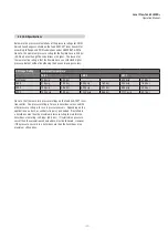
8. Commissioning
8.1 Training
Commissioning should only be conducted by qualified service
personnel according to IEC 60079-14 or MTS trained service
technicians and local regulations. MTS offers web based and in person
training for installation, commissioning, maintenance, and repair. MTS
also offers factory direct services for these same functions. Contact
MTS to discuss training or factory direct services before starting.
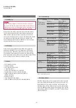
8.2 Tools
• 9/16
"
Socket and ratchet
• Channel Lock pliers
• 3/16
"
Hex Key (Allen wrench)
• 1
"
Open End wrench
• RS485 to USB Converter (MTS Part # 380114)[Modbus and DDA]
• Windows Based PC
• Linear Regulated Power Supply
• MTS Setup Software
• HART
®
to USB Converter (MTS Part # 380068)
8.3 Setup software
MTS offers Setup Software that is shipped with the level transmitter
and is also available for download from www.mtssensors.com. The
Setup Software is to be used for installation, commissioning, and
troubleshooting. For further details on how to use the setup software
consult the Modbus Interface Manual (MTS Part# 551700), the DDA
Interface Manual (MTS Part# 551701), and HART
®
Interface Manual
(MTS Part#: 551702).
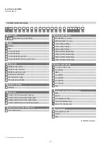
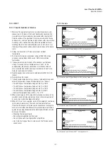
8.4 Commissioning steps
NOTICE
For Additional details consult the protocol specific Modbus Interface
Manual (MTS Part #551700), DDA Interface Manual (MTS Part
#551701), and HART
®
Interface Manual (MTS Part #551702).
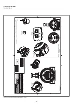
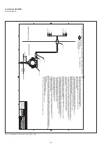
8.4.1 Modbus or DDA
1. Consult chapter 4.3 before starting.
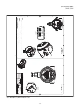
2. Remove level transmitter from shipping container.
3. Remove bottom fixing nut, washer, spacer, and stop collar.
4. Insert flexible hose into float(s) making sure float(s) are in the
active range. Install product float first.
5. Connect power, RS485 to USB converter, and PC.
6. Open MTS Setup Software.
7. Establish Communication.
8. For DDA Interface – Set Address. Default 192.
9. For Modbus Interface – Set Address, Enter Strap Table, Setup
Volume Correction Method. Default address 247.
10. Disconnect Power and Communication. Remove floats. Prepare
flexible level transmitter for transport to the top of the tank.
11. Complete Installation in chapter 6.4.
12. Have qualified technician perform hand measurement. Enter hand
measurement into MTS Setup Software and calibrate.
13. Store all settings as backup file according to site name and tank
number.
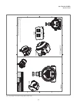
8.4.2 HART
®
1. Consult chapter 4.3 before starting
2. Remove level transmitter from shipping container.
3. Remove bottom fixing nut, washer, spacer, and stop collar.
4. Insert flexible hose into float(s) making sure float(s) are in the
active range.
5. Connect power, HART
®
to USB converter, and PC
6. Open MTS Setup Software.
7. Establish Communication.
8. Set/Update 4 and 20 mA setpoints
9. Disconnect Power and Communication. Remove floats. Prepare
flexible level transmitter for transport to the top of the tank.
10. Complete Installation in chapter 6.4.
11. Have qualified technician perform hand measurement. Enter hand
measurement into MTS Setup Software and calibrate.
12. Store all settings as backup file according to site name and tank
number.


