background image

Safety • Assembly • Operation • Tips & Techniques • Maintenance • Troubleshooting • Parts Lists • Warranty

Warning: 

This unit is equipped with an internal combustion engine and should not be used on or near any uniiproved forest-covered, brush-

covered or grass-covered land unless the engine’s exhaust system is equipped with a spark arrester meeting applicable local or state laws (if any). 
If a spark arrester is used, it should be maintained in effective working order by the operator. In the State of California the above is required by law 
(Section 4442 of the California Public Resources Code). Other states may have similar laws. Federal laws apply on federal lands. A spark arrester 
for the muffler is available through your nearest engine authorized service dealer or contact the service department, P.O. Box 361131 Cleveland, 
Ohio 44136-0019.

MTD LLC, P.O. BOX 361131 CLEVELAND, OHIO 44136-0019

READ SAFETY RULES AND INSTRUCTIONS CAREFULLY BEFORE OPERATION

IMPORTANT

OPERATOR’S MANUAL

PRINTED IN U.S.A

06/22/2006

FORM NO. 769-01275D

Two-Stage Snow Thrower — E, F Style

Содержание 769-01275D

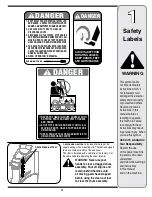
Страница 1: ...ned in effective working order by the operator In the State of California the above is required by law Section 4442 of the California Public Resources Code Other states may have similar laws Federal laws apply on federal lands A spark arrester for the muffler is available through your nearest engine authorized service dealer or contact the service department P O Box 361131 Cleveland Ohio 44136 001...

Страница 2: ...bling this product or have any questions regarding the controls operation or maintenance of this unit you can seek help from the experts Choose from the options below Safety Labels 3 Safe Operation Practices 4 Setting Up Your Snow Thrower 6 Operating Your Snow Thrower 8 MakingAdjustments 12 Maintaining Your Snow Thrower 14 Off SeasonStorage 18 Trouble Shooting 19 Illustrated Parts List 20 Warranty...

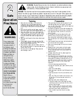
Страница 3: ...o the top of the auger housing with a mounting clip The tool is designed to clear a chute assembly of ice and snow This item is fastened with a cable tie at the factory Cut the cable tie before operating the snow thrower WARNING Never use your hands to clear a clogged chute assembly Shut off engine and remain behind handles until all moving parts have stopped before using the clean out tool to cle...

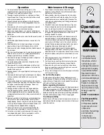
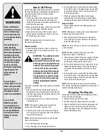
Страница 4: ...nd machine adjust to outdoor temperature before starting to clear snow 9 To avoid personal injury or property damage use extreme care in handling gasoline Gasoline is extremely flammable and the vapors are explosive Serious personal injury can occur when gasoline is spilled on yourself or your clothes which can ignite Wash your skin and change clothes immediately a Use only an approved gasoline co...

Страница 5: ...ck their proper operation regularly Refer to the maintenance and adjust ment sections of this manual 2 Before cleaning repairing or inspecting machine disen gage all control levers and stop the engine Wait until the auger impeller come to a complete stop Disconnect the spark plug wire and ground against the engine to prevent unintended starting 3 Check bolts and screws for proper tightness at freq...

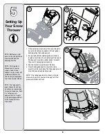
Страница 6: ...sembly over the base 4 Close the flange keepers to secure the chute assembly to the chute base The flange keepers will click into place when properly secure NOTE If the flange keepers will not easily click into place use the palm of your hand to apply swift firm pressure to the back of each NOTE Two replacement auger shear pins and bow tie cotter pins are provided for your convenience Store in a s...

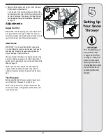
Страница 7: ...sily picked up and thrown by the auger causing personal injury or damage to the snow thrower The snow thrower skid shoes are adjusted upward at the factory for shipping purposes Adjust them downward if desired prior to operating the snow thrower Refer to Skid Shoes on page 13 NOTE If you choose to operate the snow thrower on a gravel surface keep the skid shoes in position for maximum clearance be...

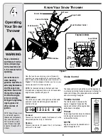
Страница 8: ...aids in starting the engine Throttle Control The throttle control is located on the engine It regulates the speed of the engine and will shut off the engine when pushed down completely Primer Depressing the primer forces fuel directly into the engine s carburetor to aid in cold weather starting Oil Fill Engine oil level can be checked and oil added through the oil fill WARNING Read understand and ...

Страница 9: ...rted in order for the engine to start Remove the ignition key when the snow thrower is not in use Do not turn the ignition key in an attempt to start the engine Doing so may cause it to break Recoil Starter Handle This handle is used to manually start the engine Electric Starter Button Pressing the electric starter button engages the engine s electric starter when plugged into a 120V power source ...

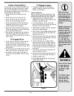
Страница 10: ... disconnecting the extension cord always unplug the end at the three prong wall outlet before unplugging the opposite end from the snow thrower Recoil Starter 1 Rotate choke control to FULL choke position cold engine start NOTE If the engine is already warm place choke control in the OFF position instead of FULL 2 Push the primer two or three times for cold engine start making sure to cover vent h...

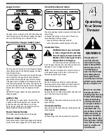
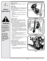
Страница 11: ... at the start of each winter Check the adjustment of the auger control as follows 1 When the auger control is released and in the disengaged up position the cable should have very little slack It should NOT be tight 2 In a well ventilated area start the snow thrower engine as instructed on the previous page Make sure the throttle is set in the FAST position 3 While standing in the operator s posit...

Страница 12: ...turn The unit should not roll freely 3 With the drive control released move the shift lever back and forth between the R2 position and the F6 position several times There should be no resistance in the shift lever 4 If any of the above tests failed the drive cable is in need of adjustment Proceed as follows 5 Loosen the lower hex nut on the drive cable bracket See Figure 4 6 Position the bracket u...

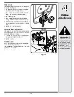
Страница 13: ... on each side and carriage bolts Move skid shoes to desired position 2 Make certain the entire bottom surface of skid shoe is against the ground to avoid uneven wear on the skid shoes 3 Retighten nuts and bolts securely Chute Bracket Adjustment If the spiral at the bottom of the chute directional control is not fully engaging with the chute assembly the chute bracket can be adjusted To do so 1 loo...

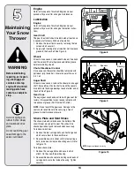
Страница 14: ...aft At least once a season remove the shear pins on auger shaft Spray lubricant inside shaft around the spacers Also lubricate the flange bearings found at either end of the shaft See Figure 9 Gear Case The auger gear case has been filled with grease at the factory If disassembled for any reason lubricate with two ounces of grease Part Number 737 0168 NOTE Do not overfill the gear case Damage to t...

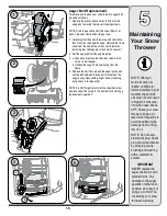
Страница 15: ...m around the auger pulley and slip the belt between the support bracket and the auger pulley Reassemble auger belt by following instructions in reverse order NOTE Do NOT forget to reinstall the shoulder screw and reconnect the spring to the frame after installing a replacement auger belt NOTE Although multi viscosity oils 5W30 10W30 etc improve starting in cold weather these multi viscosity oils a...

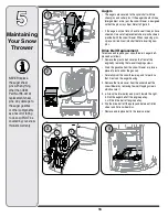
Страница 16: ...e gasoline from the snow thrower or place a piece of plastic under the gas cap Carefully pivot the snow thrower up and forward so that it rests on the auger housing 2 Remove the frame cover from the underside of the snow thrower by removing four self tapping screws which secure it 3 a Grasp the idler pulley and pivot it toward the right b Roll the auger belt off the engine pulley c Lift the drive ...

Страница 17: ...ownward and to the left before carefully sliding the friction wheel assembly off the shaft NOTE If you re replacing the friction wheel assembly as a whole discard the worn part and slide the new part onto the hex shaft Follow the steps above in reverse order to reassemble components If you re disassem bling the friction wheel and replacing only the rubber ring proceed as follows 4 Remove the four ...

Страница 18: ...s and will cause serious starting problems 1 Run the engine until the fuel tank is empty and it stops due to lack of fuel Do not attempt to pour fuel from the engine WARNING Never use engine or carbu retor cleaning products in the fuel tank or permanent damage may occur 2 Remove the spark plug and pour one 1 ounce of engine oil through the spark plug hole into the cylinder Cover spark plug hole wi...

Страница 19: ...enter 1 Carburetor not adjusted properly Loss of power 1 Connect and tighten spark plug wire 2 Remove ice and snow from gas cap Be certain vent hole is clear 3 Contact MTD Service Center 1 Spark plug wire loose 2 Gas cap vent hole plugged 3 Exhaust port plugged Unit fails to propel itself 1 Adjust drive control cable Refer to Making Adjustments 2 Replace drive belt 1 Drive control cable in need of...

Страница 20: ...20 Styles E F ...

Страница 21: ...y Auger 26 684 04073 Housing Assembly Auger 28 29 684 04107 Spiral Assembly LH 30 684 04108 Spiral Assembly RH 31 731 04870 Spacer 1 25 OD x 75 ID x 1 00 32 736 0188 Washer Flat 76 x 1 49 x 06 33 741 0493A Bushing Flange 80 ID x 91 OD 34 790 00087A Housing 1 Hex Bearing 35 790 00117 Shave Plate 2 25 x 21 66 790 00120 Shave Plate 2 25 x 23 66 790 00121 Shave Plate 2 25 x 25 66 790 00118 Shave Plate...

Страница 22: ...22 Styles E F ...

Страница 23: ...Lock 21 732 04238 Spring Torsion 0 8156 ID x 3038 22 725 04220 Wire Harness Lamp 23 735 0199A Bumper Rubber 62 OD x 22 24 736 0262 Washer Flat 385 x 870 x 092 25 738 04118 Bolt Shoulder 5 16 18 x 0 905 26 738 04122 Screw Shoulder 43 x 1 3 1 4 20 27 731 04869 Chute Flange Keeper 28 746 04228 Cable Speed Selector 29 746 0605 Houlder Cable Barrel LH 30 747 04263 Eye Bolt Chute Crank 31 790 00202 Shif...

Страница 24: ...40 33 30 24 36 18 5 25 37 19 6 31 7 30 24 26 13 23 45 47 44 23 28 43 2 7 5 34 24 30 51 58 52 61 35 27 7 14 55 48 46 7 59 59 49 41 2 1 11 4 66 A B B A 8 26 16 64 7 29 17 3 9 54 60 57 56 60 20 10 15 12 38 69 45 65 23 67 68 70 Styles E F ...

Страница 25: ... 25 741 0245 Bearing Hex Flange x 75 ID 26 741 0563 Bearing Ball 17 x 40 x 12 27 746 04229 Clutch Cable Wheel 44 95 28 746 04228 Cable Speed Selector 29 748 0190 Spacer 508 ID x 75 OD x 68 30 756 0625 Roller Cable 31 790 00096 Front Guide Bracket Auger Cable 32 790 00180 Frame 33 790 00206A Guide Bracket Auger Cable 34 790 00207A Guide Bracket Drive Cable 35 790 00226 Cover Frame 36 See Chart Whee...

Страница 26: ...NOTES 26 ...

Страница 27: ...NOTES 27 ...

Страница 28: ... of the exterior finish due to use or exposure d Service completed by someone other than an authorized service dealer e MTD does not extend any warranty for products sold or exported outside of the United States its possessions and territories except those sold through MTD s authorized channels of export distribution f Replacement parts that are not genuine MTD parts g Transportation charges and s...

Отзывы: