background image

10

SECTION 5:  MAKING ADJUSTMENTS

WARNING: 

Never attempt to make any

adjustments while the engine is running,
except where specified in operator’s
manual.

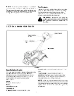
Handle Adjustment

The handle height may be adjusted to the desired 
height. Refer to the handle adjustment in Know Your 
Tiller section.

Belt Tension Adjustment

Periodic adjustment of the belt tension may be required 
due to normal stretch and wear on the belt. Adjustment 
is needed if the tines or wheels seem to hesitate while 
turning, but the engine maintains the same speed.

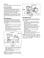
To adjust the tension on the belt, refer to Final Clutch 
Adjustment in Assembly Instructions.

After belt tension has been adjusted, if the belt is 
excessively stretched, you may need to adjust the idler 
pulley rod. This can easily be checked.

With the engine off and the clutch control bail 
disengaged, shift the gear selection handle to each 
forward mode. If the indicator bracket touches the idler 
pulley rod (with the clutch control bail disengaged), then 
an adjustment is necessary.

Disconnect and ground out spark plug wire against 
the engine.

Remove the belt cover as described under Belt 
Replacement in the Maintenance section.

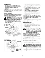
Remove the hairpin clip and spring washer from the 
idler pulley rod. Refer to Figure 9.

Move the idler pulley rod to the lower hole in the 
idler bracket.

Replace the spring washer and hairpin clip.

Check clearance of the idler pulley rod to the 
indicator bracket by shifting to each forward mode, 
as before.

Engine Adjustment

Refer to the separate engine manual for engine 
adjustment instructions.

SECTION 6:  MAINTAINING YOUR TILLER

WARNING: 

Disconnect the spark plug

wire and ground it against the engine
before performing any repairs or
maintenance.

Engine

Refer to the separate engine manual for engine 
maintenance instructions.

Maintain 

engine oil

 as instructed in the separate 

engine manual packed with your unit. Read and follow 
instructions carefully.

Service 

air cleaner

 every ten hours under normal 

conditions. Clean every hour under extremely dusty 
conditions. Poor engine performance and flooding 
usually indicates that the air cleaner should be 
serviced. To service the air cleaner, refer to the 
separate engine manual packed with your unit.

IMPORTANT:

 Never run your engine without air cleaner 

completely assembled.

The 

spark plug

 should be cleaned and the gap reset 

every 25 hours of engine operation. Spark plug 
replacement is recommended at the start of each tiller 
season; check engine manual for correct plug type and 
gap specification.

Clean the engine

 regularly with a cloth or brush. Keep 

the cooling system (blower housing area) clean to 
permit proper air circulation which is essential to engine 
performance and life. Be certain to remove all dirt and 
combustible debris from muffler area.

Lubrication

Transmission

The transmission is pre-lubricated and sealed at the 
factory. It requires no checking unless the transmission 
is disassembled. To fill with grease, lay the right half of 
the transmission on its side, add 22 ounces of 
Benalene 920 grease, and assemble the left half to it. 
This grease can be obtained at your nearest authorized 
dealer by ordering part number 737-0300.

Clutch Handle

Lubricate the pivot point on the clutch handle and the 
cable at least once a season with light oil. The control 
must operate freely in both directions.

Pivot Points

Lubricate all pivot points and linkages at least once a 
season with light oil.

Tine Shafts

Remove tine assemblies and lubricate the tine shafts at 
least once a season.

Содержание 454

Страница 1: ...ith a spark arrester meeting applicable local or state laws if any If a spark arrester is used it should be maintained in effective working order by the operator In the State of California the above is required by law Section 4442 of the California Public Resources Code Other states may have similar laws Federal laws apply on federal lands A spark arrester for the muffler is available through your...

Страница 2: ...future reference please copy the model number and the serial number of the equipment in the space below ENGINE INFORMATION The engine manufacturer is responsible for all engine related issues with regards to performance power rating specifications warranty and service Please refer to the engine manufacturer s Owner s Operator s Manual packed separately with your unit for more information CONTACTIN...

Страница 3: ... Loose fitting clothes or jewelry can be caught in movable parts Never operate this machine in bare feet or sandals 3 Disengage clutch levers and shift if provided into neutral N before starting the engine 4 Never leave this machine unattended with the engine running 5 Never attempt to make any adjustments while engine is running except where specifically recommended in the operator s manual 6 To ...

Страница 4: ...y attachments and accessories approved by the manufacturer Failure to do so can result in personal injury 21 If situations occur which are not covered in this manual use care and good judgment Contact your dealer or telephone 1 800 800 7310 for assistance and the name of your nearest servicing dealer Maintenance Storage 1 Never tamper with safety devices Check their proper operation regularly 2 Ch...

Страница 5: ...Unthread the T knob from the top of the depth stake and remove the flat washer and hex bolt Remove the hairpin clip from the clevis pin See Figure 1 Raise the tine shield hinge flap assembly and insert the depth stake assembly in the slot under the tine shield and up through the tine shield assembly Insert clevis pin through the tine shield and depth stake assemblies Secure with hairpin clip Inser...

Страница 6: ... Service the engine with oil and gasoline before checking this adjustment Refer to the separate engine manual packed with your tiller for proper fuel and engine oil recommendations Position the tiller so the front counterweight is against a solid object such as a wall With the gear selection lever in NEUTRAL start the engine Refer to the separate engine manual Standing on the right side of the til...

Страница 7: ...ction handle is located in the center of the handle on the tiller It is used to select NEUTRAL REVERSE or one of the FORWARD mode Pull or push the handle so that the indicator on top of shift cover points to the operating mode desired See Figure 6 Neutral Transmission is in neutral Reverse Reverse wheel drive Forward Modes Wheels Forward Forward wheel drive only Tines Reverse Forward wheel drive a...

Страница 8: ...s and warnings on the machine and in this manual before operating Before Starting Gas And Oil Fill Up Service the engine with gasoline and oil as instructed in the separate engine manual packed with your tiller Read instructions carefully WARNING Use extreme care when handling gasoline Gasoline is extremely flammable and the vapors are explosive Never fuel machine indoors or while the engine is ho...

Страница 9: ... depth stake to the desired setting and secure with the clevis pin and hairpin clip See Figure 7 To adjust the side shields remove the wing nuts Move the side shield to the desired position and replace the wing nuts Tighten securely Operating the Tiller Select the depth stake setting Start engine as instructed on the previous page Move gear selection handle to one of the forward modes or reverse W...

Страница 10: ... the engine before performing any repairs or maintenance Engine Refer to the separate engine manual for engine maintenance instructions Maintain engine oil as instructed in the separate engine manual packed with your unit Read and follow instructions carefully Service air cleaner every ten hours under normal conditions Clean every hour under extremely dusty conditions Poor engine performance and f...

Страница 11: ... engine pulley by removing two hex bolts and lock washers See Figure 9 Remove belt and reassemble new belt Follow instructions in reverse order NOTE Upon reassembly make certain the belt is routed over the idler pulley and inside of belt keepers by engine pulley See Figure 9 Figure 9 Off Season Storage If the tiller will not be used for a period longer than 30 days the following steps should be ta...

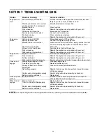
Страница 12: ... stabilizer is used Clear vent Drain fuel tank Refill with fresh fuel Refer to the engine manual packed with your unit Refer to the engine manual packed with your unit Engine over heats Engine oil level low Dirty air cleaner Air flow restricted Carburetor not adjusted properly Fill crankcase with proper oil Refer to the engine manual packed with your unit Refer to the engine manual packed with you...

Страница 13: ...13 Notes ...
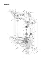
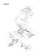
Страница 14: ...54 52 13 29 35 16 53 35 16 46 31 28 12 45 17 17 44 36 6 3 33 15 27 5 36 43 4 20 40 21 1 34 18 10 42 23 7 22 36 8 47 32 37 50 25 10 9 24 36 51 34 45 26 41 36 35 16 29 19 49 44 33 14 35 16 2 14 28 35 16 14 11 48 14 ...

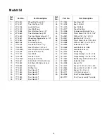
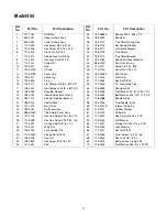
Страница 15: ... Gear 30T 24 717 1584 Spur Gear 30T 25 717 1585 Spur Gear 44T 26 717 1587 Spur Gear 44T 27 717 1594 Spur Gear 16T 28 721 0378 Seal 1 0 Shaft 29 721 0379 Seal 75 Shaft 31 726 0277 Taper Cap Ring 32 732 0496 Compression Spring 50 Leg 33 736 0163 Thrust Wash 1 03 I D X 1 62 34 736 0351 Fl Wash 76 I D x 1 5 O D 35 736 0407 Bell Wash 45 I D x 1 0 36 736 0518 Thrust Wash 445 x 1 92 x 060 37 736 3088 Fl ...

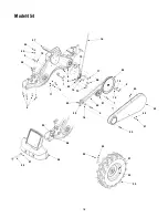
Страница 16: ...20 18 8 23 10 1 60 61 37 62 25 34 27 64 30 39 63 26 32 36 33 31 29 66 26 41 30 30 24 28 35 40 26 49 44 50 59 51 65 53 55 56 54 57 58 44 46 42 4 9 11 16 6 3 14 7 19 5 17 2 60 61 12 15 12 38 21 22 67 70 70 68 69 27 26 ...

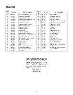
Страница 17: ...Nut 5 16 18 31 726 0106 Cap Nut 32 738 0849 Hex Screw 5 16 18 x 75 33 747 0432 Rod 34 750 0885A Spacer 322 x 625 x 2 0 35 786 0090 Shoulder 36 786 0113 Tine Shield Hinge Flap 37 786 0176 RH Handle Bracket 38 786 0177 LH Handle Bracket 39 786 0178 Tine Shield 40 786 0179 Tine Shield Bracket 41 786 0180 Shoulder Spacer Bracket 42 686 0109 Shift Crank Ass y 44 710 1017 Screw 1 4 14 x 625 46 715 0120 ...

Страница 18: ...18 Model 454 18 17 24 19 27 45 44 12 26 9 6 1 8 25 14 28 20 2 11 4 22 23 16 5 21 7 13 15 3 40 43 42 41 39 32 33 31 30 29 36 34 37 38 35 10 ...

Страница 19: ... 0064A Idler Bracket 26 786 0186 Belt Keeper Bracket 27 786 0187 Shift Cover Bracket 28 786 0193 Idler Belt Keeper 29 634 0238 Wheel Assembly RH 16 0 x 4 6 634 0239 Wheel Assembly LH 16 0 x 4 6 734 0808 Tire Only 16 2 x 4 6 30 634 0108 Wheel Rim Assembly 31 734 0255 Air Valve 32 711 1017 Clevis Pin 33 714 0104 Internal Cotter Pin 34 710 0382 Hex Bolt 1 2 13 x 5 0 35 712 0206 Hex Nut 1 2 13 36 731 ...

Страница 20: ...djustments and normal deterioration of the exterior finish due to use or exposure d Service completed by someone other than an authorized service dealer e MTD does not extend any warranty for products sold or exported outside of the United States its possessions and territories except those sold through MTD s authorized channels of export distribution f Replacement parts that are not genuine MTD p...

Отзывы: