background image

23

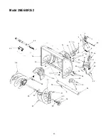
Model 31AE640F352

REF.

NO.

PART

NO.

DESCRIPTION

1

710-1652

Hex Washer Screw 1/4-20 x .625

2

731-1324

Belt Cover

3

732-0710

Extension Spring

4

710-0627

Hex Screw 5/16-24 x .75

5

710-3005

Hex Cap Screw 3/8-16 x 1.25

6

05896A

Drive Clutch Idler Bracket

7

748-0234

Shoulder Spacer

8

756-0987

Pulley Half

9

754-0346

V-Belt

10

756-0986

Pulley Half

11

736-0270

Bell Washer

12

710-0230

Hex Cap Screw 1/4-28 x .50

13

756-0313

Flat Idler

14

710-1245A

Lock Hex Cap Screw 5/16-24

15

712-0181

Lock Jam Nut 3/8-16

16

756-0569

Pulley Half

17

736-0242

Bell Washer

18

736-0505

Flat Washer

19

754-0430A

Belt

20

756-0967

Auger Pulley

21

736-0247

Flat Washer 3/8 x 1.25 OD

22

736-0331

Bell Washer

23

710-0696

Hex Cap Screw 3/8-24

24

748-0360

Pulley Adapter

25

710-0654A

Hex Screw 3/8-16 x 1.0

26

629-0071

Extension Cord, Three-Prong

REF.

NO.

PART

NO.

DESCRIPTION

1

2

3

4

5

6

7

4

8

9

10

11

12

13

15

14

16

17

18

19

20

19

16

16

16

20

21

22

23

24

25

26

IMPORTANT: 

For a proper working machine, use Factory Approved Parts.

V-BELTS 

are specially designed to engage and disengage safely. A substitute

(non OEM) V-Belt can be dangerous by not disengaging completely.

Содержание 31AE640F352

Страница 1: ... applicable local or state laws if any If a spark arrester is used it should be maintained in effective working order by the operator In the State of California the above is required by law Section 4442 of the California Public Resources Code Other states may have similar laws Federal laws apply on federal lands A spark arrester for the muffler is available through your nearest engine authorized s...

Страница 2: ...py the model number and the serial number of the equipment in the space below ENGINE INFORMATION The engine manufacturer is responsible for all engine related issues with regard to performance power rating specifications warranty and service Please refer to the engine manufacturer s Owner s Operator s Manual packed separately with your unit for more information CALLING CUSTOMER SUPPORT Please do N...

Страница 3: ... the auger impeller 2 Always wear safety glasses or eye shields during operation and while performing an adjustment or repair to protect your eyes Thrown objects which ricochet can cause serious injury to the eyes 3 Do not operate without wearing adequate winter outer garments Do not wear jewelry long scarves or other loose clothing which could become entangled in moving parts Wear footwear which ...

Страница 4: ...cessories approved by the manufacturer e g wheel weights tire chains cabs etc 20 If situations occur which are not covered in this manual use care and good judgment Contact your dealer or telephone 1 800 800 7310 for assistance and the name of your nearest servicing dealer MAINTENANCE AND STORAGE 1 Never tamper with safety devices Check their proper operation regularly Refer to the maintenance and...

Страница 5: ... the lower handle See Figure 1 Raise the upper handle assembly until it aligns with lower handle Be sure both cables are aligned with cable roller guides located in the lower rear of snow thrower frame Secure the upper handle and lower handle with the plastic wing nuts cupped washers and carriage bolt eyebolt on the left side previously removed Adjust the eyebolt on the chute directional control s...

Страница 6: ...to stop This same control also locks the auger control so you can turn the chute directional control without interrupting the snow throwing process If the auger control is engaged with the traction control engaged the operator can release the auger control on the left handle and the augers will remain engaged Release the traction control to stop both the augers and wheel drive auger control must a...

Страница 7: ...ontrol Test on page 8 of this manual Attach spark plug wire to spark plug Make certain the metal loop on end of the spark plug wire inside the boot is fastened securely over the metal tip on the spark plug See Figure 5 Figure 5 Make certain the fuel shut off valve if so equipped is in the OPEN vertical position Make certain the auger and traction controls are in the disengaged released position Mo...

Страница 8: ...ug to prevent accidental starting while equipment is unattended To prevent starter freeze up Run engine for a few minutes before stopping to help dry off any moisture on the engine Electric Starter Connect power cord to switch box on engine then to 120 volt AC receptacle With the engine running push starter button and spin the starter for several seconds The unusual sound made by spinning the star...

Страница 9: ...the rear of the auger housing 4 Use the shovel shaped end of the clean out tool to remove any snow and ice in the discharge chute WARNING Never use your hand to clear a clogged discharge chute Shut off engine and remain behind handles until all moving parts have stopped before unclogging 5 Refasten the clean out tool to the mounting clip on the rear of the auger housing re start the engine 6 While...

Страница 10: ...action control cable and unthread the cable one turn If the wheels do not stop when you engage the traction control grip loosen the jam nut on the traction control cable and thread the cable in one turn Recheck the adjustment and repeat as necessary Tighten the jam nut to secure the cable when correct adjustment is reached WARNING Drain the gasoline out of snow thrower engine place a piece of plas...

Страница 11: ...damage to the snow thrower Drive Wheels The wheels may be adjusted for two different methods of operation The adjustment is made by placing the click pins in one of two different holes on the right side of the unit See Figure 10 Figure 9 Figure 10 One Wheel Driving Insert the click pin only through the outside hole of the axle not the rim on the right side of the snow thrower This position gives p...

Страница 12: ...o 737 0168 IMPORTANT Do not overfill the gear case Damage to the seals could result Be sure the vent plug is free of grease in order to relieve pressure Auger Shaft At least once a season remove shear bolts on auger shaft Oil or spray lubricant inside shaft Also lubricate the auger bearings at least once a season See Figure 11 Chute Directional Control The worm gear on the chute directional contro...

Страница 13: ...e new shave plate making sure heads of the carriage bolts are to the inside of the housing Tighten securely Belt Replacement WARNING Disconnect the spark plug wire from the spark plug and ground Auger Belts NOTE It is necessary to remove both auger belts in order to change either one If changing just one belt be certain to check the condition of the other belt Remove the plastic belt cover on the ...

Страница 14: ...ve the klick pins which secure the wheels and remove the wheels from the axle Using a wrench to hold the shaft loosen but do not completely remove the hex nut and bell washer on left end of gear shaft See Figure 17 Lightly tap the hex nut to dislodge the ball bearing from the right side of frame Remove the hex nut and bell washer from left end of shaft Slide the gear shaft to the right and slide t...

Страница 15: ...ine or stale fuel Water or dirt in fuel system Carburetor out of adjustment Move choke lever to OFF position Clean fuel line fill tank with clean fresh gasoline Fuel may not last over thirty days unless a fuel stabilizer is used Drain fuel tank Refill with fresh fuel Refer to the engine manual packed with your unit or have carburetor adjusted by an authorized service dealer Loss of power Spark plu...

Страница 16: ...10 11 13 12 14 3 15 16 17 18 20 18 20 21 22 26 27 28 29 30 31 35 36 44 45 27 26 47 48 49 51 52 53 54 54 55 56 57 58 59 60 17 19 SECTION 10 MODEL 31AE640F352 PARTS LIST 61 26 34 23 57 24 39 32 33 63 25 54 37 38 40 41 43 50 26 42 62 ...

Страница 17: ...16 18 x 1 75 30 720 0274 Grip 31 749 0951 Lower Handle 32 710 1003 Hex Washer Screw 33 731 1393 Handle Panel for top mount lamp 34 736 0451 Saddle Washer 35 736 0242 Bell Washer 340 ID x 872 OD 36 747 0621 Lower Shift Rod 37 726 0100 Push Cap 38 720 0201A Chute Knob 39 749 0953A Upper Handle LH 749 0952A Upper Handle RH 40 705 5204A Chute Crank 42 747 0697 Chute Crank Eyebolt 43 735 0234 Rubber Gr...

Страница 18: ...40F352 30 30 2 3 4 4 5 5 6 4 7 7 8 9 10 11 12 1 5 13 14 15 16 17 18 1 19 20 41 22 23 24 25 25 26 28 29 43 1 1 31 32 33 34 8 35 Drive Clutch Cable Auger Clutch Cable 36 20 37 38 39 40 27 42 21 Auger Clutch Cable 44 45 ...

Страница 19: ...k Pin 27 684 0042B Friction Wheel Assembly 28 656 0012A Friction Disc Wheel 29 684 0013B Wheel Shift Rod Assembly 30 710 0599 Self tapping Screw 1 4 20 x 5 31 748 0190 Spacer 32 684 0021 Friction Wheel Bracket Assembly 33 732 0264 Extension Spring 34 712 0711 Jam Nut 3 8 24 35 746 0898B Drive Cable 36 738 0830 Axle 16 Wheels 37 790 00010 Friction Plate 38 735 0243B Friction Wheel Rubber 39 718 030...

Страница 20: ...20 1 2 3 4 5 6 7 8 9 10 11 12 14 15 9 10 9 18 19 20 21 22 23 13 25 23 22 26 27 28 13 30 18 9 33 9 18 35 36 38 39 41 40 42 37 40 39 34 16 13 18 43 44 24 Model 31AE640F352 ...

Страница 21: ...ushing 20 784 5647 Chute Crank Bracket 21 731 1379C Chute Adapter 22 712 0324 Hex Lock Nut 1 4 20 23 736 0463 Flat Washer 24 731 2635 Mount Chute Clean out Tool 25 710 0703 Carriage Screw 1 4 20 x 75 26 710 0604A Hex Washer TT Screw 5 16 18 27 736 0169 Lock Washer 3 8 28 712 0798 Hex Nut 3 8 16 30 784 5580 Snow Shoe 31 731 2643 Chute Clean out Tool 32 731 2635 Mount Chute Clean out Tool 33 784 557...

Страница 22: ...09A Spiral Axle 26 5 714 0161 Key 6 715 0143 Pin Spiral 7 717 0528 Worm Gear 20T 8 717 0526 Worm Shaft 9 718 0186 Thrust Collar 10 721 0325 Grease Plug 11 721 0327 Grease Seal 12 736 0351 Flat Washer 76 x 1 5 x 030 13 736 0369 Flat Washer 508 x 1 0 x 020 14 736 0445 Flat Washer 76 x 1 5 x 060 15 741 0662 Flange Bearing 75 x 1 0 x 59 16 741 0663 Flange Bearing 75 x 1 0 x 925 17 618 0121A Gearbox As...

Страница 23: ... 24 15 712 0181 Lock Jam Nut 3 8 16 16 756 0569 Pulley Half 17 736 0242 Bell Washer 18 736 0505 Flat Washer 19 754 0430A Belt 20 756 0967 Auger Pulley 21 736 0247 Flat Washer 3 8 x 1 25 OD 22 736 0331 Bell Washer 23 710 0696 Hex Cap Screw 3 8 24 24 748 0360 Pulley Adapter 25 710 0654A Hex Screw 3 8 16 x 1 0 26 629 0071 Extension Cord Three Prong REF NO PART NO DESCRIPTION 1 2 3 4 5 6 7 4 8 9 10 11...

Страница 24: ...ce items such as lubricants filters blade sharpening tune ups brake adjustments clutch adjustments deck adjustments and normal deterioration of the exterior finish due to use or exposure d MTD LLC does not extend any warranty for products sold or exported outside of the United States its posses sions and territories except those sold through MTD LLC s authorized channels of export distribution e P...

Отзывы: