background image

P55-GD61 seres

MS-7583 (v1.x) Manboard

G52-75831X7

Содержание P55-GD61 Series

Страница 1: ... P55 GD61 series MS 7583 v1 x Mainboard G52 75831X7 ...

Страница 2: ...I is registered trademark of American Megatrends Inc Award is a registered trademark of Phoenix Technologies Ltd Sound Blaster is registered trademark of Creative Technology Ltd Realtek is registered trademark of Realtek Semiconductor Corporation JMicron is registered trademark of JMicron Technology Corporation Netware is a registered trademark of Novell Inc Revision History Revision Revision Hist...

Страница 3: ...e noted Never pour any liquid into the opening that could damage or cause electrical shock If any of the following situations arises get the equipment checked by service personnel The power cord or plug is damaged Liquid has penetrated into the equipment The equipment has been exposed to moisture The equipment does not work well or you can not get it work according to User s Manual The equipment h...

Страница 4: ...ect the interference by one or more of the measures listed below Reorient or relocate the receiving antenna Increase the separation between the equipment and receiver Connect the equipment into an outlet on a circuit different from that to which the receiver is connected Consult the dealer or an experienced radio television technician for help Notice 1 The changes or modifications not expressly ap...

Страница 5: ...e FRANÇAIS En tant qu écologiste et afin de protéger l environnement MSI tient à rappeler ceci Au sujet de la directive européenne EU relative aux déchets des équipement élec triques et électroniques directive 2002 96 EC prenant effet le 13 août 2005 que les produits électriques et électroniques ne peuvent être déposés dans les décharges ou tout simplement mis à la poubelle Les fabricants de ces é...

Страница 6: ...ducten die de merknaam MSI dragen en verkocht zijn in de EU Deze goederen kunnen geretourneerd worden op lokale inzamelingspunten SRPSKI Da bi zaštitili prirodnu sredinu i kao preduzeće koje vodi računa o okolini i prirodnoj sredini MSI mora da vas podesti da Po Direktivi Evropske unije EU o odbačenoj ekektronskoj i električnoj opremi Di rektiva 2002 96 EC koja stupa na snagu od 13 Avgusta 2005 pr...

Страница 7: ...t v místních sběrnách MAGYAR Annak érdekében hogy környezetünket megvédjük illetve környezetvédőként fellépve az MSI emlékezteti Önt hogy Az Európai Unió EU 2005 augusztus 13 án hatályba lépő az elektromos és elek tronikus berendezések hulladékairól szóló 2002 96 EK irányelve szerint az elektromos és elektronikus berendezések többé nem kezelhetőek lakossági hulladékként és az ilyen elektronikus be...

Страница 8: ...5 Chapter 2 Hardware Setup 2 1 Quick Components Guide 2 2 CPU Central Processing Unit 2 3 Memory 2 7 Power Supply 2 9 Back Panel 2 10 Connectors 2 12 Jumpers 2 18 Button 2 19 Slots 2 20 LED Status Indicators 2 26 Chapter 3 BIOS Setup 3 1 Entering Setup 3 2 The Main Menu 3 4 Standard CMOS Features 3 6 Advanced BIOS Features 3 8 Integrated Peripherals 3 10 Power Management Setup 3 12 H W Monitor 3 1...

Страница 9: ...el SATA RAID B 1 Introduction B 2 BIOS Configuration B 3 Installing Driver B 10 Installing Software B 12 RAID Migration Instructions B 16 Recovery Volume Creation B 23 Degraded RAID Array B 26 Appendix C JMicron RAID Introduction C 1 Introduction C 2 JMicron RAID BIOS Utility C 3 Deleting RAID set C 7 Installing Driver C 11 JMicron RAID Configurer C 13 ...

Страница 10: ......

Страница 11: ...rd The P55 GD61 Series mainboards are based on Intel P55 chipsets for optimal system efficiency Designed to fit the advanced Intel Lynnfield LGA1156 processor the P55 GD61 Series deliver a high performance and professional desktop platform solution Chapter 1 Getting Started ...

Страница 12: ...lease visit http www msi com index php func testreport LAN Supports Dual LAN 10 100 1000 by Realtek RTL8111DL Audio Chip integrated by Realtek ALC889 True Blu ray Audio ALC888S VC2 Flexible 8 channel audio with jack sensing Compliant with Azalia 1 0 Spec IDE 1 IDE port by JMicron JMB363 Supports Ultra DMA 66 100 133 mode Supports PIO Bus Master operation mode SATA 6 SATAII SATA1 6 ports by Intel P...

Страница 13: ...al 1 Power button 1 OC Genie button 2 Base clock control buttons Slots 2 PCI Express 2 0 x16 slots if you intend to install two expansion cards into both PCI_E2 PCI_E5 slots these two PCIE x16 lanes will auto arrange from x16 x0 to x8 x8 1 PCI Express 2 0 x4 slot 2 PCI Express 2 0 x1 slots 2 PCI slots support 3 3V 5V PCI bus Interface Form Factor ATX 30 5cm X 24 4 cm Mounting 9 mounting holes If y...

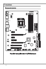
Страница 14: ...JUSB2 JUSB1 JFP2 JFP1 PCI_E1 PCI_E2 PCI_E3 PCI_E4 PCI_E5 PCI1 PCI2 LGA 1156 DIMM2 DIMM1 DIMM4 DIMM3 ATX1 LED1 LED3 LED5 LED2 LED4 LED6 SYSFAN2 SYSFAN3 CPUFAN FDD 1 BATT POWER1 IDE1 SATA1_2 SATA7 SATA3_4 SATA5_6 JCI1 JBAT1 Top mouse Bottom keyboard Top LAN Jack Bottom USB ports USB ports T M B Line In Line Out Mic T RS Out M CS Out B SS Out OC Genie USB ports ...

Страница 15: ...ATA Cable Optional Power Cable USB Bracket Optional Standard Cable for IDE Devices CrossFireX Video Link Cable Packing Checklist The pictures are for reference only and may vary from the packing contents of the product you purchased Back IO Shield User s Guide ...

Страница 16: ......

Страница 17: ...tion be careful in holding the components and follow the installation procedures For some components if you install in the wrong orientation the components will not work properly Use a grounded wrist strap before handling computer components Static electricity may damage the compo nents Chapter 2 Hardware Setup ...

Страница 18: ...7 Base clock control buttons p 2 19 OC Genie p 2 19 POWER1 p 2 9 POWER2 p 2 19 SYSFAN3 p 2 14 ATX1 p 2 9 IDE1 p 2 12 SYSFAN2 p 2 14 FDD1 p 2 12 SATA1 7 p 2 13 JFP1 JFP2 p 2 15 JUSB1 3 p 2 15 JCOM1 p 2 14 JSPDO1 p 2 16 JCD1 p 2 16 JAUD1 p 2 16 PCI p 2 25 JCI1 p 2 13 JTPM1 p 2 17 PCIE p 2 20 SYSFAN1 p 2 14 JBAT1 p 2 18 ...

Страница 19: ...ation Replacing the CPU While replacing the CPU always turn off the ATX power supply or unplug the power supply s power cord from the grounded outlet first to ensure the safety of CPU Overclocking This mainboard is designed to support overclocking However please make sure your components are able to tolerate such abnormal setting while doing overclocking Any attempt to operate beyond product speci...

Страница 20: ...e CPU cooler correctly Wrong installation will cause the damage of your CPU mainboard Open the load level 1 Lift the load lever up to fully open position 2 The CPU socket has a plastic cap on it to protect the contact from damage Before you install CPU always cover it to protect the socket pin Romove the cap as the arrow shows 3 After confirming the CPU direction for correct mating put down the CP...

Страница 21: ...e load lever while pressing down lightly onto the load plate 6 Secure the lever near the hook end under the retention tab 7 Make sure the four hooks are in por per position before you install the cooler 8 Important Confirm if your CPU cooler is firmly installed before turning on your system Do not touch the CPU socket pins to avoid damaging Alignment Key ...

Страница 22: ...earance of your mainboard may vary depending on the model you purchase Please refer to the documentation in the CPU fan package for more details about the CPU fan installation Align the holes on the mainboard with the heatsink Push down the cooler until its four clips get wedged into the holes of the mainboard 9 Press the four hooks down to fasten the cooler 10 Turn over the mainboard to confirm t...

Страница 23: ... The following illustrations explain the population rules for Dual Channel mode 1 DIMM2 DIMM1 DIMM4 DIMM3 2 DIMM2 DIMM1 DIMM4 DIMM3 Important DDR3 memory modules are not interchangeable with DDR2 and the DDR3 standard is not backwards compatible You should always install DDR3 memory modules in the DDR3 DIMM slots In Dual Channel mode make sure that you install memory modules of the same type and d...

Страница 24: ...it in until the golden finger on the memory module is deeply inserted in the DIMM slot The plastic clip at each side of the DIMM slot will automatically close when the memory module is properly seated Manually check if the memory module has been locked in place by the DIMM slot clips at the sides Notch Volt Important You can barely see the golden finger if the memory module is properly inserted in...

Страница 25: ...3 V 1 4 1 2 V 2 3 3 V 1 5 G r o u n d 3 G r o u n d 1 6 P S O N 4 5 V 1 7 G r o u n d 5 G r o u n d 1 8 G r o u n d 6 5 V 1 9 G r o u n d 7 G r o u n d 2 2 5 V 1 0 1 2 V 2 0 R e s 8 P W R O K 2 3 5 V 1 1 1 2 V 2 1 5 V 9 5 V S B 2 4 G r o u n d 1 2 3 3 V ATX 8 pin Power Connector POWER1 This connector is used to provide 12V power output to the CPU 7 1 2 V 3 G r o u n d 5 1 2 V 1 G r o u n d 8 1 2 V...

Страница 26: ...mouse or other USB compatible devices ESATA USB Combo Port The ESATA USB combo port is for attaching the ESATA external hard drive or USB device LAN The standard RJ 45 LAN jack is for connection to the Local Area Network LAN You can connect a network cable to it LED Color LED State Condition Left Yellow Off LAN link is not established On Steady state LAN link is established On brighter pulsing The...

Страница 27: ... jacks Line In Blue Line In is used for external CD player tape player or other audio devices Line Out Green Line Out is a connector for speakers or headphones Mic Pink Mic is a connector for microphones RS Out Black Rear Surround Out in 4 5 1 7 1 channel mode CS Out Orange Center Subwoofer Out in 5 1 7 1 channel mode SS Out Gray Side Surround Out 7 1 channel mode ...

Страница 28: ... f a sd dd f f as df dd dd dd df da sf da sa sd f as d as d as dd dd dd df as as df sd ff sd f ad f f f a sd f f f d f F l o p p y D M S I F l o p p y D M S I K dk l kd kf k kk f d kk l dd f k kk sd df dd f as dk a df d df dd ad df df dd dd df ad f ad kj as j d kd f d f a sd dd f f as df dd dd dd df da sf da sa sd f as d as d as dd dd dd df as as df sd ff sd f ad ff fa sd ff fd f F l o p p y D M S...

Страница 29: ... fd fd d dd df ad f ad kj as j d kd f d f a sd d df fa sd fd d dd dd df da sf da sa sd f as d as d as d dd dd dd f a s as d f s df f s df ad f f fa sd ff fd f SATA5_6 SATA3_4 SATA1_2 SATA7 SATA1 6 supported by Intel P55 SATA7 supported by JMicron JMB363 Important Please do not fold the Serial ATA cable into 90 degree angle Otherwise data loss may occur during transmission Chassis Intrusion Connect...

Страница 30: ... e n s o r 4 C o n t r o l 1 G r o u n d 2 1 2 V 3 S e n s o r CPUFAN SYSFAN1 2 3 Important Please refer to the recommended CPU fans at processor s official website or consult the vendors for proper CPU cooling fan CPUFAN support Smart fan control You can install Control Center utility that will automatically control the CPUFAN speeds according to the actual CPUFAN tem peratures Fan cooler set wit...

Страница 31: ... D L E D P o w e r S w i t c h P o w e r L E D 7 9 R e s e r v e d 8 6 4 2 JFP1 JFP2 Front USB Connector JUSB1 JUSB2 JUSB3 This connector compliant with Intel I O Connectivity Design Guide is ideal for con necting high speed USB interface peripherals such as USB HDD digital cameras MP3 players printers modems and the like 1 0 N C 8 G r o u n d 6 U S B 1 4 U S B 1 2 V C C 1 V C C 3 U S B 0 5 U S B ...

Страница 32: ...nterface for digital audio transmission 1 V C C 2 S P D I F 3 G r o u n d S PDIF Bracket Optional Front Panel Audio Connector JAUD1 This connector allows you to connect the front panel audio and is compliant with Intel Front Panel I O Connectivity Design Guide 1 M I C L 3 M I C R 1 0 H e a d P h o n e D e t e c t i o n 5 H e a d P h o n e R 7 S E N S E _ S E N D 9 H e a d P h o n e L 8 N o P i n 6...

Страница 33: ...manual for more details and usages 1 0 N o P i n 1 4 G r o u n d 8 5 V P o w e r 1 2 G r o u n d 6 S e r i a l I R Q 4 3 3 V P o w e r 2 3 V S t a n d b y p o w e r 1 L P C C l o c k 3 L P C R e s e t 5 L P C a d d r e s s d a t a p i n 0 7 L P C a d d r e s s d a t a p i n 1 9 L P C a d d r e s s d a t a p i n 2 1 1 L P C a d d r e s s d a t a p i n 3 1 3 L P C F r a m e ...

Страница 34: ...uration With the CMOS RAM the system can automatically boot OS every time it is turned on If you want to clear the system configuration set the jumper to clear data Important You can clear CMOS by shorting 2 3 pin while the system is off Then return to 1 2 pin position Avoid clearing the CMOS while the system is on it will damage the mainboard JBAT1 Keep Data Clear Data 1 1 1 ...

Страница 35: ... the default for next reboot Important Please install the DDR3 1333 and up memory and equip better heat sink cooler with OC Genie function We do not guarantee the OC Genie overclocking range and the damages or risks caused by the OC Genie overclocking behavior The usage of OC Genie is at your own risk Overclocking is never guaranteed by MSI Power On Button POWER2 This button is used to turn on or ...

Страница 36: ...nsion card PCI Express x16 Slot PCI Express x1 Slot PCI Express x4 Slot Important When adding or removing expansion cards make sure that you unplug the power sup ply first Meanwhile read the documentation for the expansion card to configure any necessary hardware or software settings for the expansion card such as jumpers switches or BIOS configuration ...

Страница 37: ...performance ATI CrossFireXTM technol ogy allows you to expand your system s graphics capabilities It allows you the ability to scale your system s graphics horsepower as you need it supporting two ATI RadeonTM HD graphics cards making this the most scalable gaming platform ever The mainboard can auto detect the CrossFireXTM mode by software therefore you don t have to enable the CrossFireXTM in BI...

Страница 38: ... a setting in the CatalystTM Control Center that needs to be enabled for CrossFireXTM to operate The following aspect appears in CatalystTM Control Center 3 Select the Advanced View from the view drop menu Important A CrossFireXTM system has four possible display modes SuperTiling Scissor Mode Alternate Frame Rendering Super Anti aliasing for more details please consult the graphics card manual fr...

Страница 39: ...equired to connect the golden fingers on the top of these two graphics cards refer to the picture below Please note that although you have installed two graphics cards only the video outputs on the first card will work Hence you only need to connect a monitor to the first PCI Express card 1 Multi GPU Link Card Important If you intend to install TWO x16 graphics cards make sure that these two graph...

Страница 40: ...Check the Enable multi GPU box to enable it for the onboard graphics cards concerning the details of multi GPU settings please refer to your graphics card manual Restart your system and a pop up message will show in the system tray confirming the Multi GPU has been enabled Important If you want to remove one graphics card and quit the function make sure the MultiGPU function is disabled 2 3 ...

Страница 41: ...ocumentation for the expansion card to configure any necessary hardware or software settings for the expansion card such as jumpers switches or BIOS configuration PCI Interrupt Request Routing The IRQ acronym of interrupt request line and pronounced I R Q are hardware lines over which devices can send interrupt signals to the microprocessor The PCI IRQ pins are typically connected to the PCI bus p...

Страница 42: ...f the LEDs will light blue when CPU is in 6 phase power mode 5 of the LEDs will light blue when CPU is in 5 phase power mode 4 of the LEDs will light blue when CPU is in 4 phase power mode 3 of the LEDs will light blue when CPU is in 3 phase power mode 2 of the LEDs will light blue when CPU is in 2 phase power mode 1 of the LEDs will light blue when CPU is in 1 phase power mode APS LEDs ...

Страница 43: ...ows you to configure the system for op timum use You may need to run the Setup program when An error message appears on the screen during the system booting up and requests you to run SETUP You want to change the default settings for cus tomized features Chapter 3 BIOS Setup ...

Страница 44: ...ms under each BIOS category described in this chapter are under continuous update for better system performance Therefore the description may be slightly dif ferent from the latest BIOS and should be held for reference only Upon boot up the 1st line appearing after the memory count is the BIOS version It is usually in the format A7583IMS V1 0 062009 where 1st digit refers to BIOS maker as A AMI W ...

Страница 45: ...can make changes to You can use the arrow keys to select the item The on line description of the highlighted setup function is displayed at the bottom of the screen Sub Menu If you find a right pointer symbol as shown in the right view ap pears to the left of certain fields that means a sub menu can be launched from this field A sub menu contains additional options for a field parameter You can us...

Страница 46: ...rated Peripherals Use this menu to specify your settings for integrated peripherals Power Management Setup Use this menu to specify your settings for power management H W Monitor This entry shows your PC health status Green Power Use this menu to specify the power phase BIOS Setting Password Use this menu to set the password for BIOS Cell Menu Use this menu to specify your settings for frequency v...

Страница 47: ...r BIOS Load Fail Safe Defaults Use this menu to load the default values set by the BIOS vendor for stable system performance Load Optimized Defaults Use this menu to load the default values set by the mainboard manufacturer specifically for optimal performance of the mainboard Save Exit Setup Save changes to CMOS and exit setup Exit Without Saving Abandon all changes and exit setup ...

Страница 48: ...This allows you to set the system to the date that you want usually the current date The format is day month date year day Day of the week from Sun to Sat determined by BIOS Read only month The month from Jan through Dec date The date from 1 to 31 can be keyed by numeric function keys year The year can be adjusted by users Time HH MM SS This allows you to set the system time that you want usually ...

Страница 49: ...A This item allows you to set the type of floppy drives installed Hold on The setting determines whether the system will stop of an error is detected at boot When the system stops of the errors preset it will halt on for 15 seconds and then au tomatically resume its operation Available options are All Error The system stops when any error is detected No Error The system doesn t stop for any detect...

Страница 50: ...on by unauthorized users or computer viruses When enabled the BIOS data cannot be changed when attempt ing to update the BIOS with a Flash utility To successfully update the BIOS you will need to disable this Flash BIOS Protection function You should enable this function at all times The only time when you need to disable it is when you want to update the BIOS After updating the BIOS you should im...

Страница 51: ...PS Multi Processor Specification version to be used for the operating system You need to select the MPS version supported by your operating system To find out which version to use consult the vendor of your operating system Primary Graphic s Adapter This setting specifies which graphic card is your primary graphics adapter PCI Latency Timer This item controls how long each PCI device can hold the ...

Страница 52: ...Onboard LAN Controller This setting allows you to enable disable the onboard LAN controller LAN Option ROM This item is used to decide whether to invoke the Boot ROM of the onboard LAN Extra RAID IDE Controller This item allows you to enable disable the onboard extra RAID IDE controller RAID Mode This item is used to select mode for extra RAID connector HD Audio Controller This setting is used to ...

Страница 53: ...ed PCI busmastering for reading writing to IDE drives On Chip SATA Controller This item allows users to enable or disable the on chip SATA controller RAID Mode This item is used to select mode for on chip SATA connectors I O Devices Press Enter to enter the sub menu and the following screen appears COM Port 1 Select an address and corresponding interrupt for the serial port ...

Страница 54: ...If your operating system supports ACPI such as Windows 2000 XP you can choose to enter the Standby mode in S1 POS or S3 STR fashion through the setting of this field Settings are S1 The S1 sleep mode is a low power state In this state no system context is lost CPU or chipset and hardware maintains all sys tem s context S3 The S3 sleep mode is a lower power state where the in formation of system co...

Страница 55: ...failure or interrupt occurred Wake Up Event Setup Press Enter and the following sub menu appears Wake up Event By Setting to BIOS activates the following fields and use the following fields to set the wake up events Setting to OS the wake up events will be defined by OS Resume From S3 By USB Device The item allows the activity of the USB device to wake up the system from S3 Sus pend to RAM sleep s...

Страница 56: ... saving modes through any event on onboard LAN device Resume By RTC Alarm The field is used to enable or disable the feature of booting up the system on a scheduled time date Date Time HH MM SS If Resume By RTC Alarm is set to Enabled the system will automatically resume boot up on a specific date hour minute second specified in these fields using the and to select the date time settings Available...

Страница 57: ...an enable a fan target value here If the current CPU fan temperature reaches to the target value the smart fan function will be activated It provides several sections to speed up for cooling down automatically CPU Min FAN speed This item will be hidden when CPU Smart FAN Target sets to Disabled This item al lows users to select the percentage of minimum speed limit for the CPU fan SYS FAN 1 2 Cont...

Страница 58: ...djust the CPU power phase according to the loading of CPU to reach the best power saving function Mainboard LED Control This item is used to turn on Auto turn off Disabled the power phase LEDs of the mainboard GreenPower Genie Icore I12V Vcore V12V These items show the amperage of Core 12V Read only ...

Страница 59: ...pear on the screen U Key This item is used to enable disable USB driver device as a key Make U Key at This item is used to specify the USB driver device as a key Change Supervisor Password This item is used to set the supervisor password Change User Password This item is used to set the user password ...

Страница 60: ...o enter it every time you try to enter Setup System This prevents an unauthorized person from changing any part of your system configuration About Supervisor Password User Password Supervisor password Can enter and change the settings of the setup menu User password Can only enter but do not have the right to change the settings of the setup menu User Access Level This item is used to limit the us...

Страница 61: ...7583 3 19 MS 7583 Cell Menu Important Change these settings only if you are familiar with the chipset Current CPU DRAM QPI Frequency These items show the current frequencies of CPU Memory and QPI Read only ...

Страница 62: ...IST The Enhanced Intel SpeedStep technology allows you to set the performance level of the microprocessor whether the computer is running on battery or AC power This field will appear after you installed the CPU which supports speedstep technology Intel C STATE C state is a power management state that significantly reduces the power of the processor during idle This field will appear after you ins...

Страница 63: ...cessor with HT Technology Chipset An Intel Chipset that supports HT Technology BIOS A BIOS that supports HT Technology and has it enabled OS An operating system that supports HT Technology For more information on Hyper threading Technology go to http www intel com products ht hyperthreading_more htm Execute Bit Support Intel s Execute Disable Bit functionality can prevent certain classes of malici...

Страница 64: ... is not guaranteed OC Stepping This item will be enabled after you set the overclocking frequency in the Adjust CPU Base Frequency MHz And the following items will appear This items will help the system to overclock step by step after system booting up Start OC Stepping From MHz This item is used to set the initial base clock The system will boot with the initial base clock and start to overclock ...

Страница 65: ... CH2 CAS Latency CL This controls the CAS latency which determines the timing delay in clock cycles before SDRAM starts a read command after receiving it CH1 CH2 tRCD When DRAM is refreshed both rows and columns are addressed separately This setup item allows you to determine the timing of the transition from RAS row ad dress strobe to CAS column address strobe The less the clock cycles the faster...

Страница 66: ... timing automatically to be determined by BIOS Setting to Manual allows you to set the following advanced memory tim ings Memory Ratio This item allows you to set the memory multiplier Adjusted DRAM Frequency MHz It shows the adjusted DRAM frequency Read only QPI Ratio This item allows you to set the QPI multiplier Adjusted QPI Frequency MHz It shows the adjusted QPI frequency Read only ClockGen T...

Страница 67: ...educes the EMI generated by modulating the pulses so that the spikes of the pulses are reduced to flatter curves Important If you do not have any EMI problem leave the setting at Disabled for optimal system stability and performance But if you are plagued by EMI select the value of Spread Spectrum for EMI reduction The greater the Spread Spectrum value is the greater the EMI is reduced and the sys...

Страница 68: ...ress the Power button to reboot the system three times Please note that to avoid electric current to affect other devices or components we suggest an interval of more than 10 seconds among the reboot actions At the fourth reboot BIOS will determine that the previous overclocking is failed and restore the default settings automatically Please press any key to boot the system normally when the follo...

Страница 69: ...IOS via the USB Storage drive directly Update BIOS ROM chip data from selected file which was be download from official website and must be saved in the root directory of the USB Stor age drive It only supports particular file name which is the official BIOS file name from us Boot After allocated particular BIOS file system will boot from this BIOS file which saved in the root directory of USB dri...

Страница 70: ...se refer to the block diagram below about the M Flash function Due to the special design of some graphics cards will cause dark screen during M flash operation and you may refer the beeps from the system to confirm the current M flash process ...

Страница 71: ...o USB drive storage drive Save File to Selected Device Please setup a specific folder in specific USB drive storage drive to save BIOS file from BIOS ROM chip data Note it only supports FAT FAT32 file system drive Save File Name as Please setup a specific name for the BIOS file which will be saved into the USB drive storage drive Note we suggest you using the official name as the default name Save...

Страница 72: ...ttings to selected profile and they are also used to load the settings from the selected profile OC Retry Count When the overclocking is failed setting this item to 1 3 5 will allow system to reboot 1 3 5 times with the overclocking configuration If the overclocking was failed every time the system will restore the defaults ...

Страница 73: ...r optimal performance of the mainboard The Fail Safe Defaults are the default values set by the BIOS vendor for stable system performance When you select Load Fail Safe Defaults a message as below appears Selecting Ok and pressing Enter loads the BIOS default values for the most stable minimal system performance When you select Load Optimized Defaults a message as below appears Selecting Ok and pr...

Страница 74: ......

Страница 75: ... provides 10 channel DAC that simul taneously supports 7 1 sound playback and 2 channels of independent stereo sound output multiple streaming through the Front Out Left and Front Out Right chan nels Appendix A Realtek Audio ...

Страница 76: ...or later before installing the driver The following illustrations are based on Windows XP environment and could look slightly different if you install the drivers in different operating systems Insert the application DVD into the DVD ROM drive The setup screen will automati cally appear Click Realtek HD Audio Drivers button 1 2 Important The HD Audio Configuration software utility is under continu...

Страница 77: ...A 3 MS 7583 Click Next to install the Realtek High Definition Audio Driver 3 Click Finish to restart the system 4 Click here Click here Select this option Click here ...

Страница 78: ... use the 2 4 6 or 8 channel audio feature now Click the audio icon from the system tray at the lower right corner of the screen to activate the HD Audio Configuration It is also available to enable the audio driver by clicking the Realtek HD Audio Manager from the Control Panel Double click ...

Страница 79: ...idor Bathroom Sewer pipe Arena and Auditorium for quick enjoyment You may choose the provided sound effects and the equalizer will adjust automatically If you like you may also load an equalizer setting or make an new equalizer setting to save as an new one by using the Load EQ Setting and Save Preset button click Reset EQ Setting button to use the default value or click Delete EQ Setting button t...

Страница 80: ...The settings are saved perma nently for future use Load Whenever you would like to use preload settings simply click this the whole list will be shown for your selection Enable Disable To disable you can temporar ily stop the sound effect without losing the settings Reset 10 bands of equalizer would go back to the default setting Delete To delete the pre saved settings which are created from previ...

Страница 81: ...w in Others you will find more optimized settings available to you Karaoke Mode Karaoke mode brings Karaoke fun back home Simply using the music you usually play Karaoke mode can help you eliminate the vocal of the song or adjust the key to accom modate your range Vocal Cancellation Single click on Voice Cancellation the vocal of the song would be eliminated while the background music is still in ...

Страница 82: ...fter you pluging the speakers into the jacks on the front panel Multi Stream Function Realtek audio supports an outstanding feature called Multi Stream which means you may play different audio sources simultaneously and let them output respectively from the indicated real panel or front panel This feature is very helpful when 2 people are using the same computer together for different purposes Cli...

Страница 83: ...m the rear panel which is the default setting Then you must to select the Realtek HD Audio 2nd output from the scroll list first and use a different program to play the second audio source for example use Winamp to play MP3 files You will find that the second audio source MP3 music will come out from the Line Out audio jack of Front Panel ...

Страница 84: ... single or multiple volume controls or to completely mute sound output Tool Show the following volume controls This is to let you freely decide which volume control items to be displayed Advanced controls Enable playback multi streaming With this function you will be able to have an audio chat with your friends via headphone stream 1 from front panel while still has music stream 2 from back panel ...

Страница 85: ...completely mute sound input Tool Show the following volume controls This is to let you freely decide which volume control items to be displayed Enable recording multi streaming Important Realtek audio allows you to record the CD Line Mic and Stereo Mix channels simul taneously frees you from mixing efforts At any given period you may choose 1 of the following 4 channels to record ...

Страница 86: ...eaker for 5 1 Speaker Output 8CH Speaker for 7 1 Speaker Output Speaker Configuration Plug the speakers in the corresponding jack Dialogue connected device will pop up for your selection Please select the device you have plugged in If the device is being plugged into the correct jack you will be able to find the icon beside the jack changed to the one that is same as your device If not correct Rea...

Страница 87: ...front panel Please check if front jacks on your system are so called AC 97 jacks If so please check this item to disable front panel jack detection Mute rear panel output when front headphone plugged in Enable auto popup dialogue when device has been plugged in Once this item checked the dialog Connected device would automatically pop up when device plugged in ...

Страница 88: ...the signal from degrading when it is converted to analog Output Sampling Rate 44 1KHz This is recommend while playing CD 48KHz This is recommended while playing DVD or Dolby 96KHz This is recommended while playing DVD Audio 192KHz This is recommended while playing High quality Audio Output Source Output digital audio source The digital audio format such as wav mp3 midi etc will come out through S ...

Страница 89: ...d make testing sound If any speaker fails to make sound then check whether the cable is inserted firmly to the connector or replace the bad speakers with good ones Or you may click the auto test button to test the sounds of each speaker automatically Center Front Right Side Right Subwoofer Rear Right Front Left Side Left Rear Left ...

Страница 90: ...om being recorded by micro phone together with your sound For example you might have chance to use VOIP function through Internet with your friends The voice of your friend will come out from speakers playback However the voice of your friend might also be recorded into your microphone then go back to your friend through Internet In that case your friend will hear his her own voice again With AEC ...

Страница 91: ...7583 3D Audio Demo In this tab you may adjust your 3D positional audio before playing 3D audio applications like gaming You may also select different environment to choose the most suitable environment you like ...

Страница 92: ...Audio Controller Audio Codec You may also select the language of this utility by choosing from the Language list Also there is a selection Show icon in system tray Switch it on and an icon will show in the system tray Right click on the icon and the Audio Accessories dialogue box will appear which provides several multimedia features for you to take advantage of ...

Страница 93: ...annel Audio Function mode properly in the software utility connect your speakers to the correct phone jacks in accordance with the setting in software utility 2 Channel Mode for Stereo Speaker Output Line In Line Out Front channels MIC No function No function No function 1 2 3 4 5 6 ...

Страница 94: ...A 20 Realtek Audio 4 Channel Mode for Stereo Speaker Output Line In Line Out Front channels MIC Line Out Rear channels No function No function 1 2 3 4 5 6 ...

Страница 95: ...A 21 MS 7583 6 Channel Mode for Stereo Speaker Output Line In Line Out Front channels MIC Line Out Rear channels Line Out Center and Subwoofer channel No function 1 2 3 4 5 6 ...

Страница 96: ...els MIC Line Out Rear channels Line Out Center and Subwoofer channel Line Out Side channels Important To enable 7 1 channel audio out function on Windows Vista operating system you have to install the Realtek Audio Driver Or the mainboard will support 5 1 channel audio out only 1 2 3 4 5 6 ...

Страница 97: ...This appendix will assist users in configuring and en abling RAID functionality on platforms Appendix B Intel SATA RAID ...

Страница 98: ...ata striping at the byte level and also stripe error correction informa tion This results in excellent performance and good fault tolerance Level 5 is one of the most popular implementations of RAID RAID 10 Not one of the original RAID levels multiple RAID 1 mirrors are created and a RAID 0 stripe is created over these Intel Matrix RAID Technology is the advanced ability for two RAID volumes to sh...

Страница 99: ...te and reset RAID volumes Using the Intel Matrix Stroage Manager Option ROM Creating Deleting and Resetting RAID Volumes The Serial ATA RAID volume may be configured using the RAID Configuration utility stored within the Intel RAID Option ROM During the Power On Self Test POST the following message will appear for a few seconds Important The Drvice Model Serial and Size in the following example mi...

Страница 100: ...ap pear Create RAID Volume Select option 1 Create RAID Volume and press Enter key The following screen appears Then in the Name field specify a RAID Volume name and then press the TAB or Enter key to go to the next field Use the arrow keys to select the RAID level best suited to your usage model in RAID Level 1 2 ...

Страница 101: ...r arrow or down arrow keys to scroll through the available values and pressing the Enter key to select and advance to the next field The available values range from 4KB to 128 KB in power of 2 increments The strip value should be chosen based on the planned drive usage Here are some typical values RAID0 128KB RAID10 64KB RAID5 64KB Then select the capacity of the volume in the Capacity field The d...

Страница 102: ...le if you want the first volume to span the first half of the two disks re type the size to be half of what is shown by default The second volume when created will automati cally span the remainder of two hard drives Then the following screen appears for you to confirm if you are sure to create the RAID volume Press Y to continue 6 Then the following screen appears to indicate that the creation is...

Страница 103: ...currently boots to RAID and you delete the RAID volume in the Intel RAID Option ROM your system will become unbootable Select option 2 Delete RAID Volume from the main menu window and press Enter key to select a RAID volume for deletion Then press Delete key to delete the selected RAID volume The following screen appears Press Y key to accept the volume deletion ...

Страница 104: ...y RAID structures from the drives The following screen appears Press Y key to accept the selection Important You will lose all data on the RAID drives and any internal RAID structures when you perform this operation Possible reasons to Reset Disks to Non RAID could include issues such as incom patible RAID configurations or a failed volume or failed disk ...

Страница 105: ...ions Select option 4 Recovery Volume Options and press Enter to change recovery volume mode The following screen appears Recovery mode will change from Continuous Update to On Request after you en able Only Recovery Disk or Only Master Disk ...

Страница 106: ...Press the S key to select Specify Additional Device You should be prompted to insert a floppy disk containing the Intel RAID driver into the A drive Note For Windows XP you can use the USB floppy drive only For Windows Vista you can use CD DVD USB drive 1 2 3 For Windows Vista During the Operating system installation after selecting the location to install Vista click on Load Driver button to inst...

Страница 107: ...Intel RAID Drivers The drivers will be automatically installed Confirming Windows Vista XP Driver Installation From Windows Vista XP open the Control Panel from My Computer followed by the System icon Choose the Hardware tab then click the Device Manager tab Click the in front of the SCSI and RAID Controllers hardware type The driver Intel R PCH SATA RAID Controller should appear 1 2 3 4 1 2 3 ...

Страница 108: ...m which the system is booting or a hard drive that contains important data For this reason you cannot remove or un install this driver from the system after installation however you will have the ability to un install all other non driver components Insert the MSI DVD and click on the RAID block and then choose INTEL RAID Drivers to install the software Click on this item Choose this item ...

Страница 109: ...MS 7583 B 13 MS 7583 The InstallShield Wizard will begin automatically for installation showed as following Click on the Next button to proceed the installation in the welcoming window ...

Страница 110: ... 14 Intel SATA RAID Intel SATA RAID The window shows the components to be installed Click Next button to continue After reading the license agreement in the following window click Yes button to con tinue ...

Страница 111: ...83 B 15 MS 7583 The following window appears to show the Readme File Information It shows the sys tem requirements and installation information Once the installation is complete the following window appears ...

Страница 112: ...elerator RAID Driver during Windows Setup Refer to Installing Software for instructions on installing the driver during Windows Setup Install the Intel Matrix Storage Console after the operating system is installed To create a volume from an existing disk complete the following steps Important A Create from Existing Disk operation will delete all existing data from the added disk and the data cann...

Страница 113: ...m Existing Disk To create a RAID volume from an existing disk choose Action Create RAID Volume from Existing Hard Drive The Create RAID Volume from Existing Hard Drive Wizard pops up to lead you for the following procedure Click Next to continue ...

Страница 114: ... data storage RAID 5 Useful RAID 5 can be used on three or more disks with zero or more spare disks The resulting RAID 5 device size will be N 1 S where N is the how many drive S is the size of the smallest drive in the array If one of the disks fail all data are still intact It can rebuild the disk from the parity information If spare disks are available recon struction will begin immediately aft...

Страница 115: ...ips 16KB Best for sequential transfers 32KB Good for sequential transfers 64KB Good general purpose strip size 128KB Best performance for most desktops and workstations 2 Select the source disk Then select the source disk that you wish to use and then click to move it to the Selected field Then click Next to continue It is very important to note which disk is the source disk the one containing all...

Страница 116: ...member disk the target disk that you wish to use and then click to move it to the Selected field Then click Next to continue Please note that the existing data on the selected hard drive s will be deleted perma nently Do not forget to back up all the important data before continuing ...

Страница 117: ...pace will be worked as RAID 1 volume which is the new technology called Intel Matrix RAID Then click Next to continue 5 Start Creating RAID Volume from Existing Hard Drive Wizard Before you continue the procedure of RAID volume creation from existing hard drive read the dialogue box below carefully Please note that once you click Finish the existing data on the selected hard drive s will be delete...

Страница 118: ...us While you can still continue using your computer during the migration process once the migration process starts it cannot be stopped If the migration process gets interrupted and your system is rebooted for any reason it will pick up the migration process where it left off You will be provided with an estimated completion time the remaining time will depend on your system once the migration pro...

Страница 119: ...lected as the recovery drive Back up all important data before beginning these steps Recovery Volume in Advanced Mode Creation To create a recovery volume in Advanced mode use the following steps Open the Intel Matrix Storage Console Start All Programs Intel Matrix Stor age Manager Intel Matrix Storage Console Select Advanced Mode in the View menu Select Create Recovery Volume in the Actions menu ...

Страница 120: ...tel SATA RAID Select a hard drive to be used as the recovery hard drive for the recovery volume 7 Modify the recovery volume name if you wish Select a hard drive to be used as the master hard drive for the recovery volume 5 6 ...

Страница 121: ...MS 7583 B 25 MS 7583 Select an update policy 8 Select Finish to begin recovery volume creation 9 ...

Страница 122: ...the procedure below that corre sponds to the current situation Missing Hard Drive Member Make sure the system is powered off Reconnect the hard drive Reboot the system to Windows the rebuild will occur automatically Failed Hard Drive Member Make sure the system is powered off Replace the failed hard drive with a new one that is of equal or greater capacity Reboot the system to Intel RAID Option RO...

Страница 123: ...em When prompted to rebuild the RAID volume click Yes The Intel R Storage Utility will be launched Right click the new hard drive and select Rebuild to this Disk The Rebuild Wizard will be launched which will guide you through the process of rebuilding to the new hard drive 5 6 7 ...

Страница 124: ......
Страница 125: ...n configuring and en abling RAID functionality on platforms The JMicron RAID solution supports RAID level 0 strip ing RAID level 1 mirroring RAID level 10 striping and mirroring and JBOD Concatenate Appendix C JMicron RAID Introduction ...

Страница 126: ...AID 1 provides data redundancy by mirroring data between the hard drives and provides enhanced read performance RAID 10 Not one of the original RAID levels multiple RAID 1 mirrors are created and a RAID 0 stripe is created over these JBOD provides a method for combining drives of different sizes into one large disk Important This mainboard supports RAID 0 RAID 1 or JBOD mode only The least number ...

Страница 127: ...sk Drive Create a new legacy RAID set Delete RAID Disk Drive Delete a legacy RAID set Revert HDD to Non RAID Revert an existed RAID HDD to non RAID Solve Mirror Conflict Sovle a mirror conflict Rebuild Mirror Drive Rebuild data when RAID 1 or RAID 10 data mirroring is lost Save And Exit Setup Save all settings and exit the BIOS utility Exit Without Saving Exit the BIOS utiltiy without any saving H...

Страница 128: ...AID set Select Create RAID Disk Drive Then press Enter 1 Then in the Name field specify a RAID set name and then press the Enter to go to the next field 2 Choose a 0 Striped a 1 Mirror or a JBOD Concatenate combination set and then press Enter to go to the next step 3 ...

Страница 129: ...ection 4 Then select the block value stripe value for the RAID array by using the upper arrow or down arrow keys to scroll through the available values and pressing the Enter key to select and advance to the next field The available values range from 4KB to 128 KB The default and typical value for RAID 0 is 128KB This field only available for RAID 0 mode 5 ...

Страница 130: ...nfirm Cre ation field The Creation field will display a message to ask you to confirm the creation Then press Y key to proceed with the RAID set creation 6 7 Then the following screen appears to indicate that the creation is finished 8 Go to the Save And Exit Setup field and press Enter a message will display to ask you to confirm the setup Then press Y key to save the setting and exit the BIOS ut...

Страница 131: ...D set Select Delete RAID Disk Drive Then press Enter 1 In the RAID Disk Driver List menu use Space key to select the RAID set you want to delete Then press Del key Press Y to accept the deletion when a deletion message is appeared 2 3 ...

Страница 132: ...isks you want to revert then click Enter key The fol lowing screen appears press Y key to remove any RAID structures from the drives Important You will lose all data on the RAID drives and any internal RAID structures when you perform this operation Possible reasons to Revert HDD to non RAID could include issues such as incom patible RAID configurations or a failed volume or failed disk ...

Страница 133: ...ws you to set the source drive and rebuild the Mirror drive accord ing to the contents of the source drive To solving a Mirror conflict Select Solving a Mirror Conflict and press Enter In the Hard Disk Driver List menu use Space key to select the disks you want to set as source drive Using the TAB move to the RAID Disk Drive List menu and highlight the RAID set that you want to rebuild Press Del t...

Страница 134: ...e Press Y to confirm otherwise press N This option allows you to rebuild the Mirror drive later and synchronize the data between two hard disks To rebuild a Mirror drive Select Rebuild Mirror Drive and press Enter Using the TAB move to the RAID Disk Drive List menu and highlight the RAID set that you want to rebuild Press Del to begin rebuilding the Mirror configuration A status bar at the bottom ...

Страница 135: ... for 32 bit OS or Flop py64 for 64 bit OS to a formatted floppy drive The driver diskette for JMicron RAID Controller is done When prompted insert the floppy disk you created in step 3 and press Enter You should be shown a list of available SCSI Adapters Select the appropriate JMicron RAID controller and press ENTER The next screen should confirm that you have selected the JMicron RAID controller ...

Страница 136: ...river tab click on JMicron JMB362 Drivers The drivers will be automatically installed Confirming Windows Vista XP Driver Installation From Windows Vista XP open the Control Panel from My Computer followed by the System icon Choose the Hardware tab then click the Device Manager tab Click the in front of the SCSI and RAID Controllers hardware type The driver JMicron JMB36X Controller should appear 1...

Страница 137: ...leting a RAID Array Rebuilding RAID Arrays Solving Mirror Conflict View RAID Array Configurations Left click the Show Disks button and the information of all hard disks will display on the right side of the window Left click the name of the disk array and the information of all hard disks of the selected disk array will display on the right side of the window The information of the disk array will...

Страница 138: ...creation Create RAID from Existing Disk You can combine the Existing Disk Source disk may content OS and Data with other HD must be larger than source Disk to be RAID The data on Source Disk will be re served After RAID is built system will need to reboot Left Click the Create RAID from Existing Disk icon on the toolbar A CREATING RAID FROM EXISTING DISK wizard dialogue will display on the screen ...

Страница 139: ...RAID Way 1 Right click the name of the disk array you want to delete and the Remove menu will appear Select the Remove Raid of the pop up menu 1 A warning message appears to remind you that the data will be lost Press the Yes button if you really want to delete the disk array 2 ...

Страница 140: ...rd dialogue will display on the screen following the de scription of every step to complete the deletion 1 2 Rebuild RAID RAID 1 can be rebuild while RAID 0 JBOD cannot be rebuild There are two ways you can choose to rebuild RAID Way 1 Right click the name of the disk array you want to rebuild and the Rebuild menu will appear 1 ...

Страница 141: ...d Raid A REBUILD RAID WIZARD dialogue will display on the screen following the de scription of every step to complete the rebuilding 2 3 Way 2 If the disk array needs to rebuild then the rebuild button will be enabling on the toolbar 1 ...

Страница 142: ...D dialogue will display on the screen following the de scription of every step to complete the rebuilding 2 3 Solve Mirror Conflict If the conflict occurs it will show the REBUILDING RAID WIZARD dialogue to ask you if you want to rebuild RAID following the description of every step to rebuild the RAID ...

Отзывы: