


2-12
Hardware Setup
MS-98K1
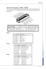
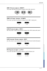
LVDS Inverter Connector: JINVDD1
The connector is provided for LCD backlight options.
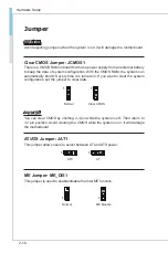
LVDS Connector: JLVDS1
The LVDS (Low Voltage Differential Signal) connector provides a digital interface
typically used with flat panels. After connecting an LVDS interface flat panel to
the JLVDS1, be sure to check the panel datasheet and set the LVDS jumper to
proper power voltage.
39.
LV
DS
B_
CL
K#
27.
LV
DS
B_
DA
TA
#1
25.
LV
DS
B_
DA
TA
1
23.
GN
D
21.
LV
DS
A_
DA
TA
#3
19.
LV
DS
A_
DA
TA
3
17.
GN
D
15.
LV
DS
A_
DA
TA
#1
13.
LV
DS
A_
DA
TA
1
11.L
VD
S_
BL
ON
9.L
_B
KLT
_C
TR
L#
7.L
VD
S_
DD
C_
CL
K
5.L
CD
_V
DD
3.L
CD
_V
DD
1.+
12V
40.
LV
DS
A_
CL
K#
28.
LV
DS
B_
DA
TA
#0
26.
LV
DS
B_
DA
TA
0
24.
GN
D
22.
LV
DS
A_
DA
TA
#2
20.
LV
DS
A_
DA
TA
2
18.
GN
D
16.
LV
DS
A_
DA
TA
#0
14.
LV
DS
A_
DA
TA
0
12.
LV
DS
_D
ET
EC
T#
_C
10.
LV
DS
_V
DD
_E
N
8.L
VD
S_
DD
C_
DA
TA
6.L
CD
_V
DD
4.+
12V
2.+
12V
37.
LV
DS
B_
CL
K
35.
GN
D
33.
LV
DS
B_
DA
TA
#3
31.
LV
DS
B_
DA
TA
3
29.
GN
D
38.
LV
DS
A_
CL
K
36.
GN
D
34.
LV
DS
B_
DA
TA
#2
32.
LV
DS
B_
DA
TA
2
30.
GN
D
Important
Pin 12 is a detect pin. When using a customized LVDS cable, pin 12 should be a
signal ground with a low impedance. Otherwise, LVDS will not function.
Содержание MS-98K1
Страница 1: ...i MS 98K1 v1 x Industrial Computer Board...
Страница 8: ......
Страница 43: ...3 11 MS 98K1 GPIO Group Configuration GPO0 GPO7 These settings control the operation mode of the specified GPIO...
Страница 57: ...3 25 MS 98K1...
Страница 65: ...3 33 MS 98K1 GPIO Group Configuration GPO0 GPO7 These settings control the operation mode of the specified GPIO...


