


2-11
Hardware Setup
MS-98K1
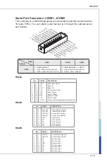
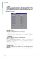
Front Panel Connector: JFP1
This front panel connector is provided for electrical connection to the front panel
switches & LEDs and is compliant with Intel Front Panel I/O Connectivity Design
Guide.
PW LED (+)
PW LED (-)
PW SW (+)
PW SW (-)
Key
2
4
6
8
10
1
3
5
7
9
HDD LED (+) HDD LED (-) Reset SW (-) Reset SW(+)
NC
LED(+)
Voltage(V)
Current(mA)
Power
5
18.51
HDD
5
18.51
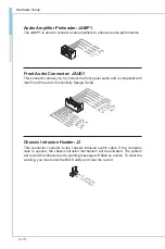
LPC Debug Port Connector: JTPM1
This connector works as LPC debug port.
1.LP
C_F
RAM
E#
2.LP
C_A
D3
3.LP
C_A
D2
4.LP
C_A
D1
5.LP
C_A
D0
6.L_
LDR
Q0#
7.TP
M_C
LK
8.SE
RIRQ
_R
9.PL
TRS
T_TP
M#
10.V
CC5
11.VC
C3
12.G
ND
13.N
A
14.G
ND
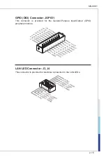
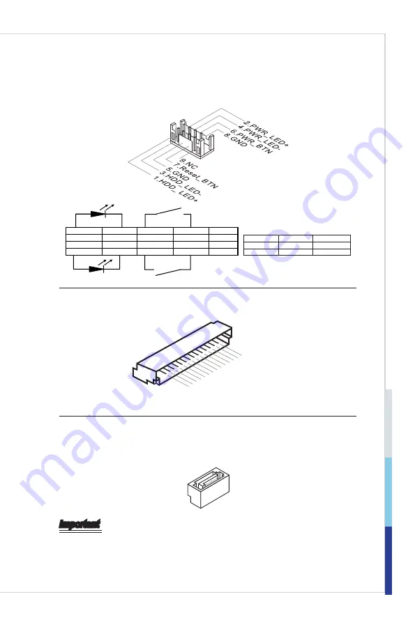
Serial ATA Connector: SATA1, SATA2
This connector is a high-speed Serial ATA interface port. Each connector can
connect to one Serial ATA device.
Important
Please do not fold the SATA cable into a 90-degree angle. Otherwise, data loss
may occur during transmission.
Содержание MS-98K1
Страница 1: ...i MS 98K1 v1 x Industrial Computer Board...
Страница 8: ......
Страница 43: ...3 11 MS 98K1 GPIO Group Configuration GPO0 GPO7 These settings control the operation mode of the specified GPIO...
Страница 57: ...3 25 MS 98K1...
Страница 65: ...3 33 MS 98K1 GPIO Group Configuration GPO0 GPO7 These settings control the operation mode of the specified GPIO...


