i
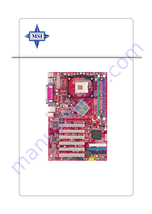
865P Neo
Version 1.0
G52-M6742X1-K01
MS-6742 (v1.X) ATX Mainboard
Страница 1: ...i 865P Neo Version 1 0 G52 M6742X1 K01 MS 6742 v1 X ATX Mainboard...
Страница 2: ...ith the instruction manual may cause harmful interference to radio communications Operation of this equipment in a residential area is likely to cause harmful interference in which case the user will...
Страница 3: ...ernational Business Machines Corporation Microsoft is a registered trademark of Microsoft Corporation Windows 98 2000 NT XP are registered trademarks of Microsoft Corporation NVIDIA the NVIDIA logo Du...
Страница 4: ...module 9 All cautions and warnings on the equipment should be noted 10 Never pour any liquid into the opening that could damage or cause electri cal shock 11 If any of the following situations arises...
Страница 5: ...PC Alert 4 1 8 D Bracket Optional 1 10 S Bracket Optional 1 12 Chapter2 HardwareSetup 2 1 Quick Components Guide 2 2 Central Processing Unit CPU 2 3 CPU Core Speed Derivation Procedure 2 3 CPU Install...
Страница 6: ...S Bracket SPDIF Connector JSP1 Optional 2 18 Front Panel Connectors JFP1 JFP2 2 20 Front Panel Audio Connector JAUD1 2 21 Front USB Connectors JUSB2 2 22 D Bracket 2 Connector JDB1 Optional 2 23 Jump...
Страница 7: ...rals 3 23 PC Health Status 3 26 Frequency Voltage Control 3 27 Set Supervisor User Password 3 29 Load Optimized Fail Safe Defaults 3 30 Appendix Using4 or6 ChannelAudioFunction A 1 Installing C Media...
Страница 8: ...6742 v1 X ATX mainboard The 865P Neo is based on Intel 865P and ICH4 chipsets for optimal system efficiency Designed to fit the advanced Intel Pentium 4 processors in 478 pin package the 865P Neo del...
Страница 9: ...1 1 controller 480Mb sec 2 channel Ultra ATA 100 bus Master IDE controller SMBus 2 0 support Integrated LAN controller AC 97 2 2 interface MainMemory h Supports two 64 bit wide DDR data channels h Av...
Страница 10: ...dio codec C Media 9739A Compliance with AC97 v2 2 Spec Meet PC2001 audio performance requirement Can support SPDIF Out via S Bracket only LAN Optional hRealtek 8101L Integrated 10 100 Ethernet MAC and...
Страница 11: ...JAUD1 JDB1 ATX Power Supply IDE 2 IDE 1 Winbond W83627THF Realtek RTL8101L Optional Top mouse Bottom keyboard USB ports T LAN jack B USB ports Cd1 JPW1 JBAT1 Codec T Line In M B Mic Line Out FDD1 AGP...
Страница 12: ...s To overclock the CPU FSB Front Side Bus frequency under the Windows operating system click FSB and use the right and left arrow keys to select the desired FSB and then click Apply to apply the new s...
Страница 13: ...d the follow ing screen will appear Five buttons are placed on the leftmost pane of the screen Click the desired button to start the update process z z z z z Live BIOS Updates the BIOS online z z z z...
Страница 14: ...will appear You can specify how often the system will automatically search for the BIOS drivers version or change the LAN settings right from the dialog box You can right click the MSI Live Monitor ic...
Страница 15: ...he program main screen will be immediately shown on the screen with the abnormal item highlighted in red This will continue to be shown until the condition returns to the normal status Users can use t...
Страница 16: ...below with information about the CPU and chipset Right click the mouse to select the skin you want to switch to Cute MSIRemindsYou 1 The new feature COOLER XP will work only if your mainboard supports...
Страница 17: ...ocking users These users can use the feature to detect if there are any problems or failures D Bracket 2 supports both USB 1 1 2 0 spec D Bracket 2 Description System Power ON The D LED will hang here...
Страница 18: ...e video adapter BIOS Sign On This will start showing information about logo processor brand name etc Testing Base and Extended Memory Testing base memory from 240K to 640K and extended memory above 1M...
Страница 19: ...l audio operation for wonderful surround sound effect or connect to Sony Philips Digital Interface SPDIF speakers for audio transmission with better quality The S Bracket offers two types of SPDIF con...
Страница 20: ...ules and expansion cards as well as how to setup the jumpers on the mainboard Also it provides the instructions on connecting the peripheral devices such as the mouse keyboard etc While doing the inst...
Страница 21: ...U p 2 3 Back Panel I O p 2 10 JPW1 p 2 9 JDB1 p 2 23 JSP1 p 2 18 JFP1 p 2 20 AGP Slot p 2 26 PCI Slots p 2 26 IDE1 IDE2 p 2 17 FDD1 p 2 15 JSP4 p 2 25 CPUFAN1 p 2 16 SYSFAN1 p 2 16 JFP2 p 2 20 JAUD1 p...
Страница 22: ...verheating If you do not find the heat sink and cooling fan contact your dealer to pur chase and install them before turning on the computer MSIRemindsYou Overheating Overheating will seriously damage...
Страница 23: ...he pins should be completely embedded into the socket and can not be seen Please note that any violation of the correct installation procedures may cause permanent damages to your mainboard 5 Press th...
Страница 24: ...the CPU Follow the instructions below to install the Heatsink Fan 2 Position the heatsink onto the reten tion mechanism 1 Locate the CPU and its retention mechanism on the motherboard 3 Mount the fan...
Страница 25: ...2 6 MS 6742 ATX Mainboard 5 Connect the fan power cable from the mounted fan to the 3 pin fan power connector on the board fan power cable NOTES...
Страница 26: ...ar to conventional SDRAM but doubles the rate by transferring data twice per cycle It uses 2 5 volts as opposed to 3 3 volts used in SDR SDRAM and requires 184 pin DIMM mod ules rather than 168 pin DI...
Страница 27: ...ill automatically close MSI Reminds You You can barely see the golden finger if the module is properly inserted in the socket Volt Notch Install at least one DIMM module on the slots Memory modules ca...
Страница 28: ...ect to the ATX power supply make sure the plug of the power supply is inserted in the proper orientation and the pins are aligned Then push down the power supply firmly into the connector ATX 12V Powe...
Страница 29: ...mouse You can plug a PS 2 mouse directly into this connector The connector location and pin assignments are as follows PIN SIGNAL DESCRIPTION 1 Mouse DATA Mouse DATA 2 NC No connection 3 GND Ground 4...
Страница 30: ...in Definition PS 2 Keyboard 6 pin Female 2 1 3 4 5 6 USB Connectors The mainboard provides a UHCI Universal Host Controller Interface Universal Serial Bus root for attaching USB devices such as keyboa...
Страница 31: ...Differential Pair 1 7 NC Not used 8 NC Not used Serial Port Connectors COM A and COM B The mainboard offers two 9 pin male DIN connectors as serial port COM A The ports are 16550A high speed communic...
Страница 32: ...connector for microphones 1 8 Stereo Audio Connectors Line Out Line In MIC MSIRemindsYou For advanced audio application CMedia 9739A is provided to offer support for 6 channel audio operation and can...
Страница 33: ...CP mode 13 1 14 25 PIN SIGNAL DESCRIPTION 1 STROBE Strobe 2 DATA0 Data0 3 DATA1 Data1 4 DATA2 Data2 5 DATA3 Data3 6 DATA4 Data4 7 DATA5 Data5 8 DATA6 Data6 9 DATA7 Data7 10 ACK Acknowledge 11 BUSY Bus...
Страница 34: ...ors to connect to FDD IDE HDD LAN USB Ports and CPU System Power Supply FAN Floppy Disk Drive Connector FDD1 The mainboard provides a standard floppy disk drive connector that supports 360K 720K 1 2M...
Страница 35: ...nnected to the 12V the black wire is Ground and should be connected to GND If the mainboard has a System Hardware Monitor chipset on board you must use a specially designed fan with speed sensor to ta...
Страница 36: ...r than earlier record breaking Ultra ATA 100 technology and is backwards compatible with the existing Ultra ATA interface IDE1 Primary IDE Connector The first hard drive should always be connected to...
Страница 37: ...offers 2 SPDIF jacks for digital audio transmission one for optical fiber connection and the other for coaxial and 2 analog Line Out jacks for 4 channel audio output To attach the fiber optic cable t...
Страница 38: ...put 10 SOUT L Audio left surrounding output 11 GND Ground 12 GND Ground JSP1 Pin Definition Optional S Bracket SPDIF jack optical SPDIF jack coaxial Analog Line Out jack Connect to JSP1 MSIRemindsYou...
Страница 39: ...MSG LED pull up 3 HD_LED_N Hard disk active LED 4 FP PWR SLP MSG LED pull up 5 RST_SW_N Reset Switch low reference pull down to GND 6 PWR_SW_P Power Switch high reference pull up 7 RST_SW_P Reset Swi...
Страница 40: ...rcuits 5 AUD_FPOUT_R Right channel audio signal to front panel 6 AUD_RET_R Right channel audio signal return from front panel 7 HP_ON Reserved for future use to control headphone amplifier 8 KEY No pi...
Страница 41: ...ases data transfer rate up to a maximum throughput of 480Mbps which is 40 times faster than USB 1 1 and is ideal for connecting high speed USB inter face peripherals such as USB HDD digital cameras MP...
Страница 42: ...se refer to D Bracket 2 in Chapter 1 Pin Signal 1 DBG1 high for green color 2 DBR1 high for red color 3 DBG2 high for green color 4 DBR2 high for red color 5 DBG3 high for green color 6 DBR3 high for...
Страница 43: ...attery to keep the data of system configuration With the CMOS RAM the system can automatically boot OS every time it is turned on If you want to clear the system configuration use the JBAT1 Clear CMOS...
Страница 44: ...t keep the jumper on to use the 6 channel audio For more information on the S Bracket please refer to p 2 18 S Bracket SPDIF Connector JSP1 Optional and the Appendix Using 4 or 6 Channel Audio Functio...
Страница 45: ...The slot supports 8x 4x AGP card PCI Peripheral Component Interconnect Slots The PCI slots allow you to insert the expansion cards to meet your needs When adding or removing expansion cards make sure...
Страница 46: ...nterrupt signals to the microprocessor The PCI IRQ pins are typically connected to the PCI bus INT A INT D pins as follows Order 1 Order 2 Order 3 Order 4 PCI Slot 1 INT A INT B INT C INT D PCI Slot 2...
Страница 47: ...etup program and allows you to configure the system for optimum use You may need to run the Setup program when An error message appears on the screen during the system booting up and requests you to r...
Страница 48: ...ility by pressing F11 When the same message as listed above appears on the screen press F11 to trigger the boot menu The POST messages might pass by too quickly for you to respond in time If so restar...
Страница 49: ...Performance defaults BIOS Setup defaults provide stable performance settings for all devices and the system while High Perfor mance defaults provide the best system performance but may affect the sys...
Страница 50: ...the values in the chipset registers and optimize your system s performance Power Management Features Use this menu to specify your settings for power management PNP PCI Configurations This entry appea...
Страница 51: ...r Password Use this menu to set Supervisor Password Set User Password Use this menu to set User Password LoadOptimalDefaults Use this menu to load factory default settings into the BIOS for stable sys...
Страница 52: ...alue you prefer System Time This allows you to set the system time that you want usually the current time The time format is hour minute second System Date This allows you to set the system to the dat...
Страница 53: ...r sector number Maximum Capacity Read the maximal HDD capacity LBA Mode Select Auto for a hard disk 512 MB un der Windows and DOS or Disabled un der Netware and UNIX Block Mode Select Auto to enhance...
Страница 54: ...1st 2nd 3rd The items allow you to set the sequence of boot devices where AMIBIOS attempts to load the operating system The settings are IDE 0 The system will boot from the first HDD IDE 1 The system...
Страница 55: ...vice BBS 4 The system will boot from the 5th BBS BIOS Boot Specification compliant device BBS 5 The system will boot from the 6th BBS BIOS Boot Specification compliant device BBS 6 The system will boo...
Страница 56: ...the hard disk becomes offline Settings Enabled Disabled BootUpNum Lock This item is to set the Num Lock status when the system is powered on Setting to On will turn on the Num Lock key when the system...
Страница 57: ...nable or disable the Hyper Threading function Setting to Enabled will increase the system performance Settings Enabled Disabled MPSRevision This field allows you to select which MPS Multi Processor Sp...
Страница 58: ...Disabled Enabled APICACPISCIIRQ This field is used to enable or disable the APIC Advanced Programmable Interrupt Controller Due to compliance to PC2001 design guide the system is able to run in APIC...
Страница 59: ...of the installed DRAM Settings are SPD 266MHz 333MHz Auto Configure SDRAM Timing by SPD Selects whether DRAM timing is controlled by the SPD Serial Presence Detect EEPROM on the DRAM module Setting to...
Страница 60: ...ay When DRAM is refreshed both rows and columns are addressed separately This setup item allows you to determine the timing of the transition from RAS row address strobe to CAS column address strobe T...
Страница 61: ...P for video purposes The aperture is a portion of the PCI memory address range dedicated to graphics memory address space Host cycles that hit the aperture range are forwarded to the AGP without any t...
Страница 62: ...his state no system context is lost CPU or chipset and hardware maintains all system context S3 STR The S3 sleep mode is a lower power state where the in formation of system configuration and open app...
Страница 63: ...Out Minute After the selected period of system inactivity all devices except the CPU shut off Settings Disabled 1 2 4 8 10 20 30 40 50 60 Power Button Function This feature sets the function of the po...
Страница 64: ...e power saving modes Settings Monitor Ignore Set WakeUp Events Press Enter and the following sub menu appears USB Device Wakeup From S3 S4 This item allows the activity of the USB device to wake up th...
Страница 65: ...enable or disable the feature of booting up the system on a scheduled time date from the soft off S5 state Settings Enabled Disabled RTCAlarmDate Hour Minute Second If Resume On RTC Alarm is set to En...
Страница 66: ...ded System Configuration Data NVRAM Non volatile Random Access Memory is where the BIOS stores resource information for both PNP and non PNP devices in a bit string format When the item is set to Yes...
Страница 67: ...riority PCI Slot2 Slot5 IRQ Priority PCI Slot3 IRQ Priority PCI Slot4 IRQ Priority These items specify the IRQ line for each PCI slot Setting options 3 4 5 7 9 10 11 Auto Selecting Auto allows BIOS to...
Страница 68: ...assed to devices that are configurable by the system BIOS The available DMA pool is determined by reading the ESCD NVRAM If more DMAs must be removed from the pool the end user can reserve the DMA by...
Страница 69: ...iver installed such as DOS and SCO Unix Set to No Mice only if you want to use any USB device other than the USB mouse Setting options Disabled No Mice All Device OnboardLAN This setting is used to en...
Страница 70: ...OM3 2E8 COM4 and Disabled OnboardParallelPort This field specifies the base I O port address of the onboard parallel port Selecting Auto allows AMIBIOS to automatically determine the correct base I O...
Страница 71: ...OS determines the IRQ for the parallel port automatically Parallel Port DMA Channel This feature needs to be configured only when Parallel Port Mode is set to the ECP mode When Parallel Port is set to...
Страница 72: ...onitor function is available only if there is hardware monitoring mechanism onboard CPU SystemTemperature CPU SystemFanSpeed Vcore 3 3V 5 0V 12 0V 12 0V 5 0V Battery 5V SB These items display the curr...
Страница 73: ...ikes of the pulses are reduced to flatter curves If you do not have any EMI problem leave the setting at No for optimal system stability and performance But if you are plagued by EMI setting to Enable...
Страница 74: ...et the CPU Vcore Adjust to Yes DDR Power Voltage Adjusting the DDR voltage can increase the DDR speed Any changes made to this setting may cause a stability issue so changing the DDR voltage for long...
Страница 75: ...When a password has been set you will be prompted to enter it every time you try to enter Setup This prevents an unauthorized person from changing any part of your system configuration Additionally wh...
Страница 76: ...erformance of the mainboard The Fail Safe Defaults are the default values set by the BIOS vendor for stable system performance When you select Load Optimized Defaults a message as below appears Pressi...
Страница 77: ...e Xear 3DTM technology a value add PC audio total solution In addtion C Media designs a Universal Driver Architecture UDA driver which has a flexible interface so that it can be applied to different p...
Страница 78: ...the best field dynamically adapted to different appliances and sound sources h A new multi channel listening mode is provided Earphone plus You can use open aired earphones in place of rear speakers t...
Страница 79: ...ying 3D audio applications like gaming 7 Demo Program Multi channel Music Multi channel Music Demo Program has three 5 1 channel melodies for playing You can also click on the speakers respectively to...
Страница 80: ...d the rest of speakers to S Bracket Use the back panel only without S Bracket If you do not have a S Bracket you can connect all speakers to the audio connectors on the back panel After installing the...
Страница 81: ...the window tray on the bottom and choose Open Then the C Media 3D Audio Configuration will appear Click on the Speaker Output tab to configure the audio Speaker Output 1 Without the optional S Bracke...
Страница 82: ...center signal is delivered by tip of the stereo plug and the bass signal is by ring of it as the figure showed below However some speakers have opposite definition Please use this option to solve the...
Страница 83: ...creen showed below Check the Speaker Test tab in the right side It shows the speaker figure and test environment complying with your speaker type settings as follows You can click Auto Test button or...
Страница 84: ...S PDIF digital output in real time This is useful to transfer the analog audio from one device to the S PDIF interface of another such as the external decoder or the amplifier of Home Theater h No Out...
Страница 85: ...nverted to digital format you have to click Select Source button and select one analog source in the Select Source window Actually the selected item synchronizes with the recording panel of Microsoft...
Страница 86: ...e level of digital audio you can enable Loudness AGC It provides extra 3dB to 12dB gain to all channels The driver has also been designed with a sophisticated auto gain control minimizing the signal c...
Страница 87: ...may select the microphone input you are going to use But if your system does not support 2 microphone inputs then you won t see two items The real panel microphone jack is sometimes shared by center...
Страница 88: ...Xear 3D tab and the following screen appears C Media UDA driver now supports Xear 3D 5 1 Virtual SPEAKER SHIRFTER and sound effects Just click the left button in Xear 3D tab and the new friendly fanc...
Страница 89: ...ron ment effects 3 environment sizes and 10 band pre set equalizer 1 Sound Effect You may choose the provided environ ments by clicking the buttons Bathroom Concert Hall Sewer Pipe and Music Pub or us...
Страница 90: ...ck each speaker to test your connection configuration Moreover it can help you to adjust your virtual speakers for multi channel audio applications like DVD 2 Demo Program This part contains multi cha...
Страница 91: ...e running The default setting for SPEAKER SHIFTER is OFF thus you have to click on it to make it ON in which all the speakers are available to adjust YoumaymoveFront Left Front Right Rear Left Rear Ri...
Страница 92: ...ound Effect tab in the Xear 3D Advanced Program Demo Program will not be installed automatically Please click C Media Sound Drivers again for the complete installation of C Media applications Please n...
Страница 93: ...el Audio Function A 17 The Xear3D Sound Play3D Demo program is showed as follows Five built in Sound Sources Six Envornment Effects which will synchronize with the Environment setting on Sound Effect...
Страница 94: ...ng 3D audio applications like gaming When clicking each of the Moving Path icons Drag Path Horizontal Circle Vertical Circle Z Path and Random Curve a rea moving ball indicates the 3D source source po...
Страница 95: ...s S Bracket is an optional accessory It gives access to analog and digital audio output by integrating both SPDIF Sony Philips Digital Interface and analog LINE OUT connectors To use the S Bracket you...
Страница 96: ...uld still attach the speakers to BACK PANEL s Line Out connector during 2 channel audio mode even though S Bracket s Line Out connectors function properly 1 MIC 2 Line Out Front channels 3 Line In 4 O...
Страница 97: ...two speakers to back panel s Line Out connector and four speakers to both Line Out connectors of S Bracket 1 MIC 2 Line Out Front channels 3 Line In 4 Optical SPDIF jack 5 Coaxial SPDIF jack 6 Line Ou...
Страница 98: ...only For digital audio output use the SPDIF Sony Philips Digital Interface connectors supplied by S Bracket First connect the SPDIF speakers to the appropriate SPDIF jack and then select the audio cha...
Страница 99: ...verclocking on Intel 865P chipset 1 MemorySpeed CPUFSBOverclockingSupportMatrix O Yes X Not avaliable CPUFSB800MHz DDR400isnotthedefaultspecificationofthismainboard If you decided to use Intel s FSB 8...
Страница 100: ...CPU FSB 133 will not be autodetected by the motherboard So user need to set the FSB manually to 133 Q Why my motherboard BIOS sticker is Phoenix BIOS but when I boot up my system I saw that Award BIO...
Страница 101: ...ownloadtheMSILiveUpdateutilityfromhttp www msi com tw support liveupdate livedriver htmbutitkeepsonfailing A This can be solved by one of the following suggestions 1 Dont install zonealarm 2 Disable W...
Страница 102: ...OS unless you really have to Q HowdoIupdatetheBIOS A Please refer to http www msi com tw support bios note htm for details Q HowdoIidentifytheBIOSversion A Upon boot up the 1st line appearing after th...
Страница 103: ...M Insert this floppy disk in the floppy drive Turn On the system and press and hold Ctrl Home to force update It will read the AMIBOOT ROM file and recover the BIOS from the A drive When 4 beeps are h...
Страница 104: ...unused frequency band of 2 45 GHz that is available globally with some variation of bandwidth in different countries In addition to data up to three voice channels are available Each device has a uni...
Страница 105: ...y circuits for transmitting and receiv ing data a PC chipset provides the electronic interfaces between all subsystems Clock Cycle Clock cycle or tick is the smallest unit of time recognized by a devi...
Страница 106: ...mass storage devices of up to 8 4 gigabytes whereas the old standard was limited to 528 MB Because of its lower cost enhanced EIDE has replaced SCSI in many areas There are four EIDE modes defined The...
Страница 107: ...rrupt Request Line IRQs are hardware lines over which devices can send interrupt signals to the microprocessor When you add a new device to a PC you sometimes need to set its IRQ number by setting a D...
Страница 108: ...s LPT1 LPT2 and LPT3 It is frequently used by the OS to identify a printer Overclocking Overclocking is resetting your computer so that the microprocessor runs faster than the manufacturer specified s...
Страница 109: ...vices to computers SCSI interfaces provide for faster data transmission rates up to 80 megabytes per second than standard serial and parallel ports In addition you can attach many devices to a single...