background image

DF-8500 

气体探测器


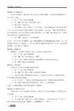
[M-14] -- 

手动增益标定


本菜单用于对探测器的增益进行手动标定。注:请尽量利用

M-02

进行自动增益标

定,仅在现场由于风速过大或者其他因素导致气体流量不稳定,从而不能利用

M-02

完成

自动增益标定时才使用

M-14

手动完成增益标定。


1


通入

M-03

中显示的浓度的标定气体一分钟之后。


2


按“

+

”键,选择菜单

M-14


3


按“

ON

”键,此时出现密码输入菜单。


4


输入密码(见

4.4

节)。


5


若密码输入正确,则进入

M-14

的下一层菜单,此时会闪烁显示

M-03

中显示的

浓度,表示此时准备进行手动增益标定工作,按“

OFF

”键则取消手动增益标定工作返

回菜单项

M-14

;按“

ON

”键则完成增益标定工作,并且自动返回到测量模式,此时可

以看到浓度显示已经为

M-03

中指定的浓度。


6


拿掉增益标定气体。


注意:对于氧气,硫化氢和一氧化碳等常规气体,请确保在探测器上电一小时


以后再进行增益标定,对于环氧乙烷,甲醇,氯乙烯等稀有气体,此时间需要


加大到二十四小时。


4.3 


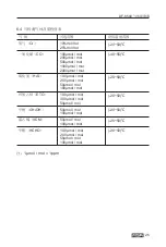
为确保产品的性能稳定,梅思安推荐用户每三个月进行一次标定,标定流

量为

0.25

/

分,并且标定应该采用梅思安规定的标定帽。长期不进行标定或


者使用不正确的标定流量及不正确的标定帽会对产品的性能造成不良影响。


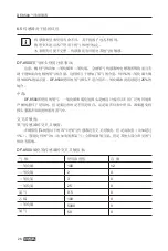
尽管设备出厂前已经标定,但是仍然建议安装后进行二次标定。传感器的使用期


和化学曝露度决定标定操作的频率。


调试时必须标定设备,之后也应定期标定,保证传感器的最佳操作


推荐标定前连接所有标定部件,以便在倒记时期间向设备输入标定气体。


待标定气体一旦标定开始就必须提供标定气体(零点或增益气体),标定结束前


不得中断供气。


21


Содержание DF-8500

Страница 1: ...MSA CHINA SAFETY EQUIPMENT CO LTD DF 8500 DF 8500 GAS DETECTOR User Manual P N 10203355 Rev 1 Date 2019 03 21...

Страница 2: ...1 1 1 1 2 4 4 4 5 6 6 6 7 8 8 10 13 13 14 21 22 22 22 23 23 23 24 25 26 27 27 28 29 29 30 31 31 30 1 3 1 4 2 2 1 2 2 3 3 1 3 2 4 4 1 4 2 4 3 4 4 5 5 1 6 6 1 6 2 6 3 6 4 6 5 7 7 1 8 9 9 1 9 2 9 3 9 4 1...

Страница 3: ...DF 8500 1 1 1 DF 8500 SUPREMA Gasgard XL 9010 9020 8020 1 2 4...

Страница 4: ...DF 8500 1 3 5...

Страница 5: ...DF 8500 1 4 1 2 12 2 2 1 1 DF 8500 6...

Страница 6: ...DF 8500 2 2 15 LED 10 11 1 2 3 4 5 7 6 9 8 12 2 DF 8500 1 2 4 15 LED 3 LED 4 LED 5 6 LED 7 LED 8 9 10 11 12 7...

Страница 7: ...DF 8500 3 3 1 3 1 1 mm 3 DF 8500 8...

Страница 8: ...DF 8500 3 1 2 DF 8500 Nut M6 Washer 6 Mounting plate Washer 6 Bolt M6 12 Clamp 2 DF 8500 Pipe 2 DF 8500 DF 8500 Nut M6 Washer 6 Mounting plate Washer 6 Bolt M6 12 Clamp 2 Pipe 2 DF 8500 4 DF 8500 9...

Страница 9: ...4V 4 20mA 24V 24V 4 20mA 24V 24V P2 P1 P3 Alarm Device Red NC COM NO H ALARM L ALARM Black FAULTRELAY NO NC JP2 JP3 1 2 1 2 COM COM 2 3 2 3 P4 NC NO 5V TXD P6 Material in the dashed RXD GND line recta...

Страница 10: ...DC 24V 4 20MA 4 20 mA NO COM NC P2 P1 P3 AF5000 NC COM NO H ALARM L ALARM FAULTRELAY NO NC COM COM P4 NC NO 5V TXD P6 Material in the dashed RXD AF5000 GND line rectangle is DF 8500 optional Remote P...

Страница 11: ...DF 8500 6 DF 8500 7 DF 8500 DC24V DC24V 4 20 mA 8 DF 8500 1 2 3 4 5 3 6 7 12 1 2 3 1 2 3 1 DC 24V 2 DC 24V 3 4 20 mA 1 2 3...

Страница 12: ...DF 8500 4 4 1 4 0mA LED LED CO H2S 1000 1000 mol mol 100 300 100 mol mol 300 mol mol 1 mol mol 1ppm 13...

Страница 13: ...DF 8500 4 2 4 2 1 1 2 4 3 IR Control 9 4 2 2 2 DF 8500 14 M 00 M 01 M 02 M 03 M 04 M 05 M 06 LED M 07 M 09 M 10 M 11 M 13 M 14 1 ON 2 OFF 3 4...

Страница 14: ...DF 8500 M 00 1 M 00 2 ON 3 4 4 4 M 01 1 M 01 2 ON 30 3 4 ON 5 0 6 OK 7 M 02 1 M 02 2 ON M 04 3 4 ON 5 6 OK 7 8 15...

Страница 15: ...DF 8500 M 03 1 M 03 2 ON TEST GAS SENSOR USED DAYS GAS M 04 1 M 04 2 ON 3 4 4 4 TEST GAS CURRENT OFFSET 5 ON 6 7 OFF M 04 16 TEST GAS SENSOR USED DAYS GAS RANGE VER Z CALI COUNTER S CALI COUNTER...

Страница 16: ...URRENT OFFSET 4 20 mA 120 90 150 4 20mA ALARM_L 10 25 19 5 5 1 0 5 0 1 mol mol V V ALARM_H 30 25 23 0 1 1 0 1 0 1 mol mol V V ZERO TIME 30 10 99 SPAN TIME 30 60 180 300 10 900 IDLE TIME 15 10 99 4 20M...

Страница 17: ...M 05 2 ON 3 4 4 4 900 15 ON OFF M 05 5 OFF M 05 ETO VCM Methanol 24 24 M 06 LED LED 1 M 06 2 ON OFF 3 LED 4 OFF M 06 M 07 4 20 mA 1 M 07 2 ON 04 4mA 3 ON 04 4mA 4 5 OFF M 07 4 22mA M 09 1 M 09 2 ON TE...

Страница 18: ...N 6 ON OFF 7 19 L_ALARM DIR 25 UP DOWN UP DOWN UP Down H_ALARM DIR UP UP DOWN ALARM RELAY DISE DISE ENER DISE ENER ALARM RELAY UNLK UNLK LOCK UNLK LOCK ALARM DELAY 0 0 30 TEMP CURRENT 4 20 mA SIGNAL C...

Страница 19: ...DF 8500 1 2 M 11 1 M 11 2 vON 3 4 4 4 M 11 OFF ON OFF M 11 M 13 M 01 M 01 M 13 1 2 M 13 3 ON 4 4 4 5 M 13 0 OFF M 13 ON 0 20...

Страница 20: ...DF 8500 M 14 M 02 M 02 M 14 1 M 03 2 M 14 3 ON 4 4 4 5 M 14 M 03 OFF M 14 ON M 03 6 4 3 0 25 21...

Страница 21: ...DF 8500 4 2 2 M 01 4 2 2 M 02 OFF 4 4 4 0000 1 2 ON 3 4 5 5 1 M 05 22...

Страница 22: ...2 23 AF5000 1 0mm 1 5mm 2 5mm 1 0mm 1 5mm 2 5mm DC 24V 3000 4500 7500 950 1400 2400 IP66 IP67 275 125 106 Ex d ia ia Ga IIC T6 Gb Ex tD A21 IP66 IP67 T80 2 5 95 16 0 34 0 V 1 5W 40 70 4 20 mA 80 120 3...

Страница 23: ...2S 30 ETO 180 VCM 180 CH3OH 300 HCHO 300 T90 O2 2 F S 20s 1 CO 10 F S 5 mol mol 15s 2 H2S 5 mol mol 25s 2 ETO 10 F S 120s 5 CH3OH 10 F S 120s 5 VCM 10 F S 120s 5 HCHO 10 F S 120s 5 1 0 50 ETO 24 0 50...

Страница 24: ...mol 500 mol mol 1000 mol mol 2000 mol mol 40 55 H2S 10 0 mol mol 20 0 mol mol 50 mol mol 100 mol mol 20 50 ETO 10 0 mol mol 30 0 mol mol 50 mol mol 20 50 CH3OH 50 mol mol 100 mol mol 20 50 VCM 50 mol...

Страница 25: ...DF 8500 6 5 DF 8500 1 0 3 DF 8500 25 DF 8500 TLV 1 DF 8500 26 100 2 2 0 3 0 25 0 0 5 0 100 0 5000 0 50 0...

Страница 26: ...DF 8500 DF 8500 DF 8500 1 2 3 4 24 5 180 300 7 DF 8500 7 1 27 100 88 100 97 100 28 48 6 14 19 5 0 5 13 7 0 5 200 0 50 0 20 0 20 0...

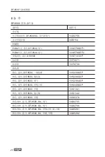
Страница 27: ...SP DF 8500 10160486 SP DF 8500 10161341 DF 8500 10161342 DF 8500 10195378 DF 8500 SIL 10202755 DF 8500 SIL 10202786 DF 8500 SIL 10205281 DF 8500 SIL 10205282 PCBA DF 8500 10145768 SP1 PCBA DF 8500 10...

Страница 28: ...DF 8500 9 9 1 29 LED 4 20 mA 4mA 4mA E XX 2mA HI 20 5mA BOOT 0mA 0 3 2mA...

Страница 29: ...E 2mA 30 BOOT E 07 Flash E 08 RAM E 09 Flash CRC E 10 E 11 ADC24 E 12 ADC10 E 13 E 14 E 16 Flash E 17 E 20 E 21 E 22 PC E 23 E 24 E 25 E 26 E 27 E 28 1 2 3 1 2 3 E 32 E 34 ADC10 E 35 ADC24 E 36 RAM L...

Страница 30: ...10 9 4 EX d Suprema Gasgard XL 9020 9010 8020 PLC DCS 24V 1 24V DC GND 2 0V DC 4 20mA 3 4 20mA RLoad max 300 31 EX d 1 24V DC 24V Suprema Gasgard XL 9020 9010 8020 PLC DCS 2 0V DC GND 3 4 20mA 4 20mA...

Страница 31: ...1 34 6 9427E 09 6 94 Oxygen gas 2 61E 04 2 61 1 36E 07 13 6 1 31631E 05 1 32 6 87451E 09 6 87 52 Toxic gas 6 83E 04 6 83 1 38E 07 13 8 3 47425E 05 3 47 7 04594E 09 7 05 Oxygen gas 6 73E 04 6 73 1 36E...

Страница 32: ...DF 8500 SIL SIL LDM HDM 72 4 20mA 4mA 20mA 5 FS 20 52 0 5A EN60950 EN50178 SELV PELV SIL 3 1oo2 4 20 mA 33 SIL SIL1 SIL2 SIL3 LDM HDM LDM HDM LDM HDM 1oo1 X X X X 1oo2 X X X X X X...

Страница 33: ...DF 8500 SJ T 11364 GB T 26572 GB T 26572 34 Pb Hg Cd Cr VI PBB PBDE DF 8500...

Страница 34: ...ajor technical parameters of the detector Cable Lengths and Cross sections Meter Primary Performance Specifications List of Detectable Gases and Measuring Ranges Sensor Response to Interferants Access...

Страница 35: ...supporting life and health Inappropriate use maintenance or servicing may affect the function of the device and thereby seriously compromise the user s life Before use the product operability must be...

Страница 36: ...concentration of the gas for which it has been calibrated Consequently calibration checks must be included as part of the routine inspection of the system As with all devices of these types high level...

Страница 37: ...ebugging maintenance etc are performed by persons other than personnel from MSA or authorized by MSA 2 The product isinappropriately placed utilized or modified Without explicit authorization by MSA a...

Страница 38: ...ur digit 15 segment LED display four LEDs for displaying the current status of the detector 10 11 1 2 3 4 5 7 6 9 8 12 Figure 2 Description of the Various Part of DF 8500 1 Terminal for power connecti...

Страница 39: ...ser to the ground for gases heavier than air Also consider how air movement may affect the ability of the device to detect as The display on the front of the instrument must always be clearly visible...

Страница 40: ...Nut M6 Washer 6 Mounting plate Washer 6 Bolt M6 12 Clamp 2 DF 8500 Pipe 2 DF 8500 Mounting on Verticalpipe DF 8500 Nut M6 Washer 6 Mounting plate Washer 6 Bolt M6 12 Clamp 2 Pipe 2 DF 8500 Mounting on...

Страница 41: ...able lengths and cross sections see chapter 6 2 Water or impurities can penetrate the instrument through the cable In hazardous areas it is recommended to install the cable in a loop just before entry...

Страница 42: ...20 mA output of device NO Not energized normally open COM Common terminal NC Not energized normally closed Passive Jumper P2 P1 P3 the black wire of AF5000 connect to COM of the low alarmrelay NC COM...

Страница 43: ...the left and right side of the plastic housing and pull the electronic module out of the enclosure 4 Insert the cable into the device 5 Connect the wire to the terminal Please use 3 wire shielded cabl...

Страница 44: ...reen red red yellow and after all the LED indicators light the green LED starts to flicker Software version Displays the firmware version Sensor type Displays the configuration information from differ...

Страница 45: ...bration No M 02 Gain calibration No M 03 Detector parameters view No M 04 Calibration parameter setting Yes M 05 Sensor replacement Yes M 06 LED testing No M 07 Loop testing No M 09 Sensor information...

Страница 46: ...urn to the measurement mode Note For conventional gas e g O2 H2S and CO please make sure the detector has been powered on for at least one hour before attempting a zero calibration For rare gas e g ET...

Страница 47: ...submenu and be able to set multiple numerous parameters When you enter the next submenu the scroll display will display parameter name parameter value which represents the name and content of the para...

Страница 48: ...t fine tuning 120 90 150 ALARM_L Low alarm point setting O2 25 range 19 5 Others 10 range No decimal point range 5 range 1 Decimal point range 0 5 range 0 1 ALARM_H High alarm point setting O2 25 rang...

Страница 49: ...splay and the LED flickers 1 Press to select menu item M 06 2 Press ON and then the screen flickers to display OFF 3 Press and then all the segments of the nixie tube with the LED diodes are lighted 4...

Страница 50: ...tion 4 6 7 After the parameters are changed you can continue to change other parameters by pressing or or return to the upper menu M 10 by pressing OFF 51 Submenu Parameter Meaning Default Adjustable...

Страница 51: ...ter the password see Section 4 4 4 If the password is correct then the device enters the next level menu of M 11 and the screen displays OFF If you press the relay status will inverse i e the original...

Страница 52: ...in the display which indicates that manual gain calibration is ready Press OFF to cancel the manual gain calibration and return to M 14 menu item Press the ON key to complete the gain calibration and...

Страница 53: ...t can be modified only by certificated and authorized personnel The default password is 0000 After entering the password menu set the number from left to right and the flicker bit means that the bit i...

Страница 54: ...5mm cable DC 24V 3000 4500 7500 950 1400 2400 Detected gas Methane Enclosure Aluminium enclosure Explosion proof Protection level IP 67 not including the sensor Dimensions mm height width depth Approx...

Страница 55: ...ror Response Time 90 Repeatability error Oxygen O2 2 F S 20s 1 Carbon monoxide CO 10 F S 5 mol mol 15s 2 Hydrogen sulfide H2S 5 mol mol 25s 2 Ethylene oxide ETO 10 F S 120s 5 Methanol CH3OH 10 F S 120...

Страница 56: ...ll increase approximately 0 3 with 1 increase of the carbon dioxide The DF 8500 oxygen sensor is not suitable for use in occasions where the carbon dioxide concentration exceeds 25 continuously Poison...

Страница 57: ...500 cross sensitivity list for the hydrogen sulfide sensor DF 8500 cross sensitivity list for the carbon monoxide sensor Precautions for using DF 8500 ETO VCM and methanol sensor 1 Must use polytetraf...

Страница 58: ...on time is reduced then thecalibrationis inaccuracysincethegas concentrationis not stablewhencalibration Only order the electrochemical sensors for immediate replacement Storage temperature range is 2...

Страница 59: ...0161342 Sensor SP DF 8500 Methanal 10195378 Sensor conductor SP DF 8500 SIL TOX 10202755 Sensor conductor SP DF 8500 SIL OX 10202786 Sensor conductor SP DF 8500 SIL ETO VCM 10205281 Sensor conductor S...

Страница 60: ...lay LED Color Status Current Signal Number Green or Red Normal or alarm 4 20 mA Green flicker Start 4mA Green flicker Calibration 4mA or follow E XX Yellow Fault 2mA HI Red Over range 20 5mA BOOT Yell...

Страница 61: ...fault Replace the electronic module E 20 Zero calibration timeout Mainboard fault Replace the electronic module E 21 Span calibration timeout Unstable zero gas flow Stabilize the zero gas flow E 22 Pe...

Страница 62: ...tes the menu will automatically return to the concentration measurement mode from any other screen 9 4 Wiring diagram Faulty Low alarm High alarm relay relay relay EX d Suprema Gasgard XL 9020 9010 80...

Страница 63: ...oxic gas 2 67E 04 2 67 1 38E 07 13 8 1 34523E 05 1 34 6 9427E 09 6 94 Oxygen gas 2 61E 04 2 61 1 36E 07 13 6 1 31631E 05 1 32 6 87451E 09 6 87 52 weeks Toxic gas 6 83E 04 6 83 1 38E 07 13 8 3 47425E 0...

Страница 64: ...bration check has to be done for the complete system A visual check has to be done together with the calibration A system check has to be done every year Calibration and adjustment are part of the fun...

Страница 65: ...20 mA output of the device must be monitored regarding deviations O Indicates that said hazardous substance contained in all of the homogeneous materials for this part is below the limit requirement...

Страница 66: ...0 888 Product technology is continuously improved andcurrentdataisfor reference only P N 10203355 Rev 1 MSA China Safety Equipment Co Ltd Tel 0512 62898880 Fax 0512 62952853 ChinaHeadquarterofMarketin...

Отзывы: