Residential Steambath Generator Systems
Installation, Operation & Maintenance Manual
Страница 1: ...Residential Steambath Generator Systems Installation Operation Maintenance Manual...
Страница 2: ...available at the time of publica tion Sussman Automatic Corporation reserves the right to make changes at any time without notice CAUTION WARNING states a hazard may cause serious injury or death if...
Страница 3: ...ing AromaSteam Essential Oils 15 Liquid Level Control Board 16 Select Your MrSteam Model 17 Replacement Parts Diagram 18 Replacement Parts List 19 Tempo Controls General Information Care Tips 20 Safet...
Страница 4: ...urfaced flooring is used provide suitable anti skid strips or equivalent to prevent user slipping and injury 4 Walls and ceilings must be constructed of water resistant non corrosive surface such as t...
Страница 5: ...tate installation and disconnection of piping 11 IMPORTANT Steam line safety valve drain valve plumbing and steamheads become hot during operation and remain hot after shutdown for a period of time Pr...
Страница 6: ...ts as shown in Diagram A Connect each end to the printed circuit board connector labeled TANDEM as shown 5 Prevent the interconnecting cable from contacting hot surfaces such as steam outlet safety va...
Страница 7: ...ad where incidental contact by bather with the steam head or direct steam emission cannot occur 1 Locate steam head 6 12 inches above floor except for Tub shower enclosures install 6 inches above tub...
Страница 8: ...3 8 60 __________________________________ M 6 152 6 3 8 162 NOTES 1 M Optional AutoFlush 2 All units in inches MM 3 MS Super 4T includes 2 MS Super 1T units 4 MS Super 5T includes 2 MS Super 2T units...
Страница 9: ...____________________________________________________________________ MS 225T 250 7 5 208 36 8 240 32 8 _________________________________________________________________________________________________...
Страница 10: ...ENT DAMAGE DO NOT CONNECT POWER SUPPLY DIRECTLY TO ELEMENTS __________________________________________________ NOTE FOR ILLUSTRATIVE PURPOSES ONLY CONSULT WITH QUALIFIED LICENSED ELECTRICIAN FOR ELECT...
Страница 11: ...NSFORMER WATER FEED SOLENOID VALVE SINGLE PHASE MS 65T MS 90T MS 150T MS 225T MS 300T MS 400T SINGLE PHASE MS SUPER 1T MS SUPER 2T MS SUPER 3T WATER FEED SOLENOID VAVLE HEATING ELEMENT CONTROL BOARD G...
Страница 12: ...N 103904 through the knock outs as shown in diagram A page 5 Connect each end to the printed circuit board as shown 5 Connect separate plumbing and power supplies for each unit Wiring Diagram MS Super...
Страница 13: ...e Manual 12 Three Phase Wiring Diagram with Tempo Plus Control Installation Instructions for Models MS Super 4T MS Super 5T and MS Super 6T 1 Install each unit as in a single installation as close to...
Страница 14: ...e minimal Every 2 months or more often in hard water areas the manual drain valve should be opened fully flushing out accumulated materials salts and other particles which are natural by products of b...
Страница 15: ...Drain Valve valve end A and B are indicated on bottom of AutoFlush Valve DO NOT REMOVE THE DRAIN VALVE Removal may cause equipment and property damage If there is not enough room for the valve an elbo...
Страница 16: ...ential oils are for external use only Keep out of reach of children Essential oils are highly concentrated and are potent substances and should not be applied directly to the skin as they can be irrit...
Страница 17: ...___ With TEMPO or TEMPO PLUS control ON _________________________________________________________________________________________________ HTR Room temperature status indicator LED is ON when control i...
Страница 18: ...ads MS SUPER 5T includes two MS SUPER 2T steam generators and one TEMPO PLUS Control and two matching AromaSteam steam heads MS SUPER 6T includes two MS SUPER 3 steam generators and one TEMPO PLUS Con...
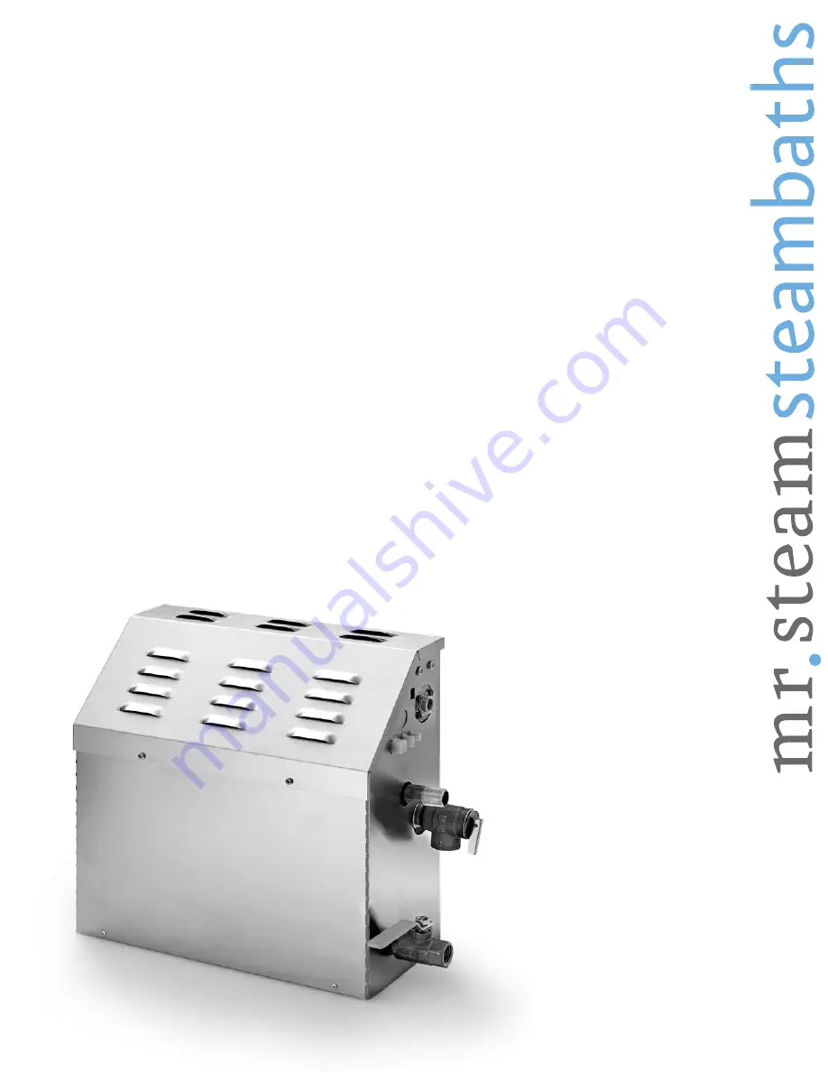
Страница 19: ...Valve Data Plate AutoFlush Valve optional Stainless Steel Tank Heating Element Access Cover Liquid Level Probe Plug and Play Connection see page 14 Power Block Power Supply Knock Out Water Feed Sussm...
Страница 20: ...pole MS Super 1T Super 6T 100471 2 Probe Assembly All models 99096 MS Heating Element Gasket All models MS 103938 Acrylic Shield All Models 99314 Power Fuse 60A 250V MS Super 1T 6T Single phase 29041...
Страница 21: ...will result in an inoperative control and overheating of the steamroom _________________________________________________________________________________________________________ Do not route Tempo Plu...
Страница 22: ...l and or steam gener ator are located accordingly Contact a MrSteam technical service representa tive if a longer cable is required If the control is installed outside the steam room a Remote Temperat...
Страница 23: ...Step 6 Run a bead of silicone provided as shown to the C shaped groove as shown in Diagram 4 IMPORTANT Do not apply excessive amounts of sili cone Do not apply silicone to any other parts of the con t...
Страница 24: ...e PAUSE mode Setting the temperature Diagram 3 The control is pre set and will display the temperature setting of 110F default setting Use the UP and DOWN keys to change the tempera ture setting from...
Страница 25: ...ly recommended to begin steambathing at a shorter duration to gauge comfort and safety levels The control will turn off when the relaxation period times out Setting the temperature Press TEMP key to s...
Страница 26: ...eet It is for use inside the steam room and requires a direct line of sight with the TEMPO PLUS Control The TEMPO REMOTE does not operate with the TEMPO Control To operate the TEMPO REMOTE simply poin...
Страница 27: ...ey NOTE The Timer continues to count down while in the PAUSE mode 2 Press PAUSE key a second time to resume the flow of steam Setting the Program Values To Set PROG 1 and PROG 2 1 Press PROG 1 or PROG...
Страница 28: ...lash twice indicating that programmed codes are still in memory If LED indicator flashes 3 times it means that programmed code settings have been erased reenter the code per instructions on page 25 In...
Страница 29: ...o not oversize or undersize the hole Route the cable from the wall to the steam generator Do not strain staple pinch or otherwise damage the control cable STEP 3 Diagram 3 Remove and discard the peel...
Страница 30: ...rom the steam head 4 Not exposed to direct steam emission The probe has an integral 30 cable Insure that the probe and or steam generator are located accordingly Contact a MrSteam technical service re...
Страница 31: ...cable and bulb into hole as required to leave minimum 1 4 maximum 1 2 of the bulb exposed as shown below Insure a minimum of 1 4 of the temperature bulb is exposed to the air Failure to do so may res...
Страница 32: ...sman Automatic Corporation info mrsteam com www mrsteam com 43 20 34th Street Long Island City NY 11101 Tel 1 800 76 STEAM Fax 718 472 3256 Western 9410 S La Cienega Blvd Inglewood CA 90301 1 800 72 S...