background image

HDA SERIES WALK-BEHIND TROWEL • OPERATION MANUAL — REV. #0 (12/1/17) — PAGE 19

SETUP

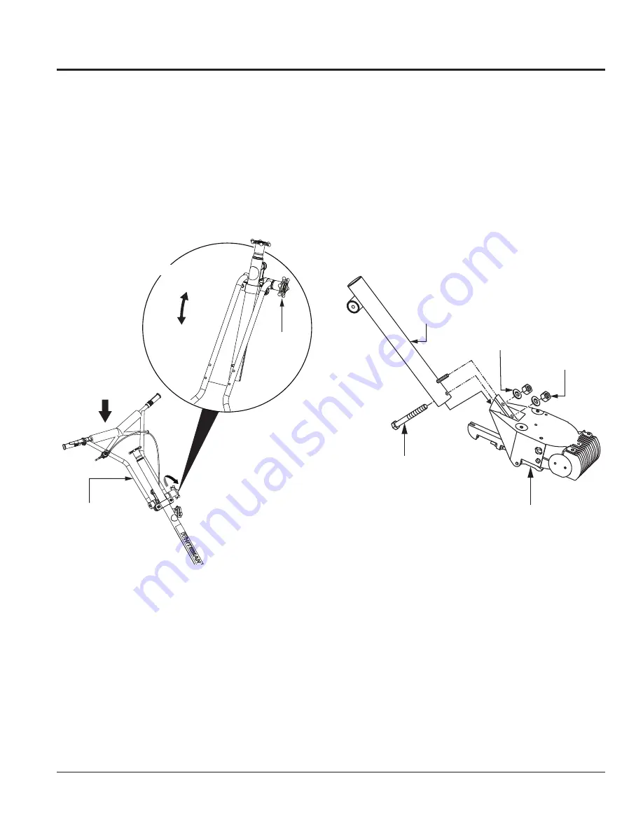
UNPACKING THE HANDLE

The trowel handle (Figure 5) is shipped in the folded, or 

stowed, position.
1.  To place the folding upper handle in the operational 

position, turn the star wheel 

counterclockwise to 

release it from its folded/stowed position.

2.  Pull back on the upper handle to place the handle in 

the operational position. Turn the star wheel 

clockwise 

to secure the handle firmly in place.

Figure 5. Unpacking the Handle

FOLDED

POSITION

OPERATIONAL

POSITION

STAR

WHEEL

UPPER

HANDLE

OPERATIONAL

POSITION

ASSEMBLY AND INSTALLATION

Some assembly and installation is required before the 

trowel can be operated. This section provides general 

assembly instructions.
For detailed handle assembly instructions, contact 

Multiquip and request the Walk-Behind Trowel Handle 

Installation Instructions (P/N 20485).

Handle Tube Installation

Attach the main handle tube to the gearbox using the 

mounting hardware contained in the shipping container 

(Figure 6).

Figure 6. Handle Tube Installation

GEARBOX

3/8 FLAT

WASHER

3/8-16 X 3.25

HHC SCREW

MAIN HANDLE

TUBE

3/8-16

NYLOC NUT

Содержание HDA SERIES

Страница 1: ...MUST ACCOMPANY THE EQUIPMENT AT ALL TIMES To find the latest revision of this publication visit our website at www multiquip com Revision 0 12 1 17 PN 13411 HDA SERIES WALK BEHIND TROWEL HONDA GX340K1QA2 GX390K1QA2 GASOLINE ENGINES ...

Страница 2: ...e State Some examples of these chemicals are Leadfromlead basedpaints Crystallinesilicafrombricks Cementandothermasonryproducts Arsenicandchromiumfromchemically treatedlumber Di lsononyl Phthalate DINP Your risk from these exposures varies dependingonhowoftenyoudothistype of work To reduce your exposure to these chemicals ALWAYS work in a well ventilated area and work with approved safety equipmen...

Страница 3: ...ase cancer birth defects or other reproductive harm If you are unfamiliar with the risks associated with the particular process and or material being cut or the composition of the tool being used review the material safety data sheet and or consult your employer the material manufacturer supplier governmental agencies such as OSHA and NIOSH and other sources on hazardous materials California and s...

Страница 4: ...Table Of Contents 4 Training Checklist 5 Daily Pre Operation Checklist 6 Safety Information 7 11 Trowel Transportation 12 Specifications 13 Dimensions 14 General Information 15 Trowel Components 16 17 Engine Components 18 Setup 19 23 Inspection 24 25 Operation 26 30 Options 31 32 Maintenance 33 41 Engine Troubleshooting 42 43 Trowel Troubleshooting 44 45 Wiring Diagram 46 ...

Страница 5: ...ponents checking of engine oil level 3 Fuel system refueling procedure 4 Operation of controls machine not running 5 Safety controls safety stop switch operation 6 Emergency stop procedures 7 Startup of machine engine choke 8 Maintaining a hover 9 Maneuvering 10 Pitching 11 Concrete finishing techniques 12 Shutdown of machine 13 Lifting of machine lifting bail 14 Machine transport and storage ...

Страница 6: ...K BEHINDTROWEL OPERATION MANUAL REV 0 12 1 17 DAILY PRE OPERATION CHECKLIST Daily Pre Operation Checklist 1 Engine oil level 2 Gearbox oil level 3 Condition of blades 4 Blade pitch operation 5 Safety stop switch operation ...

Страница 7: ... in conjunction with safety messages Warning decals associated with the operation of this equipment are defined below Inhaling exhaust fumes can result in severe injury or death Only operate equipment in well ventilated areas inhale exhaust gases fumes DO NOT WARNING Lethal Exhaust Gas Hazard HOT PARTS can burn skin CAUTION Burn Hazard touch hot parts Allow machine a sufficient amount of time to c...

Страница 8: ...n the working area when the equipment is in operation DO NOT use the equipment for any purpose other than its intended purposes or applications NOTICE This equipment should only be operated by trained and qualified personnel 18 years of age and older Whenever necessary replace nameplate operation and safety decals when they become difficult read Manufacturer does not assume responsibility for any ...

Страница 9: ...n of any of these devices will void all warranties CAUTION NEVER stand on trowel during operation NEVER lubricate components or attempt service on a running machine NEVER place your feet or hands inside the guard rings while starting or operating this equipment DANGEROUS GAS FUMES KEEP CLEAR ALWAYS keep work area clear around the trowel Make sure it is free of debris and objects NOTICE ALWAYS keep...

Страница 10: ...ners in well ventilated areas and away from sparks and flames NEVER use fuel as a cleaning agent DO NOT smoke around or near the equipment Fire or explosion could result from fuel vapors or if fuel is spilled on a hot engine TRANSPORTING SAFETY CAUTION NEVER allow any person or animal to stand underneath the equipment while lifting NOTICE Some walk behind trowels can be lifted or moved by two peop...

Страница 11: ...all other metal parts be sent to a recycling center Metal recycling involves the collection of metal from discarded products and its transformation into raw materials to use in manufacturing a new product Recyclers and manufacturers alike promote the process of recycling metal Using a metal recycling center promotes energy cost savings EMISSIONS INFORMATION NOTICE The gasoline engine used in this ...

Страница 12: ...rklift is sufficient for the weight of the trowel WARNING BE CAREFUL while lifting the trowel A dropped trowel can cause serious personal injury and damage to the trowel NEVER lift the trowel to unnecessary heights NEVER stand underneath the trowel while it is being lifted ALWAYS make sure the handle is secure and only use the manufacturer s approved lifting point The trowel can be lifted by the l...

Страница 13: ...eriesTrowel Specifications Shipping Weight 335 lb 152 kg Operating Weight 327 lb 148 kg Number of Blades 4 Rotor Speed 35 225 rpm Path Width 46 in 1 168 mm Ring Diameter 48 in 1 219 mm Table 2 Honda Engine Specifications Model GX340K1QA2 GX390K1QA2 Type Air cooled 4 stroke single cylinder OHV horizontal shaft gasoline engine Bore Stroke 3 2 in 2 5 in 82 mm 64 mm 3 5 in 2 5 in 88 mm 64 mm Displacem...

Страница 14: ...N MANUAL REV 0 12 1 17 DIMENSIONS Figure 2 HDA Series Trowel Dimensions A B C D Table 4 HDA SeriesTrowel Dimensions A Height Lifting Bale 34 5 in 876 mm B Height Engagement Lever 41 1 in 1 044 mm C Width 48 0 in 1 219 mm D Length 75 2 in 1910 mm ...

Страница 15: ...ged please contact your nearest Multiquip dealer for a replacement Continuously VariableTransmission CVT The trowel is equipped with a continuously variable transmission CVT to obtain maximum drive torque Power is transferred from the engine to the gearbox input shaft via a V belt or pulley drive system The pulley is engaged by a centrifugal clutch Gearbox Located beneath the engine the gearbox tr...

Страница 16: ...PAGE 16 HDA SERIESWALK BEHINDTROWEL OPERATION MANUAL REV 0 12 1 17 TROWEL COMPONENTS Figure 3 HDA Series Trowel Components QUICK PITCH HANDLE OPTIONAL STANDARD HANDLE 1 2 3 4 5 6 7 8 9 10 11 12 13 14 15 ...

Страница 17: ...ratory Handlebar T handle with rubber shock mounts isolators to reduce vibration during operation 9 Hand Grips 2 ALWAYS place both hands on the hand grips when maneuvering the trowel Replace the hand grips when they become worn or damaged 10 Handlebar Adjuster Loosenthestar wheel toadjust the height and angle of the handlebar as desired then tighten the star wheel firmly to secure the handlebar in...

Страница 18: ...ly to start the engine 6 FuelValve Lever Open to allow the flow of fuel and close to prevent the flow of fuel 7 Oil Drain Bolt Remove to drain oil from the engine crankcase 8 Dipstick Oil Filler Cap Remove to determine if engine oil is low Add oil through this port as recommended in 9 Choke Lever Aids in starting a cold engine or starting in cold weather conditions The choke enriches the fuel mixt...

Страница 19: ...Figure 5 Unpacking the Handle FOLDED POSITION OPERATIONAL POSITION STAR WHEEL UPPER HANDLE OPERATIONAL POSITION ASSEMBLY AND INSTALLATION Some assembly and installation is required before the trowel can be operated This section provides general assembly instructions For detailed handle assembly instructions contact Multiquip and request the Walk BehindTrowel Handle Installation Instructions P N 20...

Страница 20: ...imately 3 inches 76 mm up or down The kit comes complete with wedges bolts and installation instructions RUN THROTTLE LEVER SETUP 4 Loosen the cable housing clamp screw and the swivel stop screw Figure 9 Figure 9 Throttle Cable Installation 5 Place the return spring between the cable housing clamp and the swivel stop screw Figure 9 6 Feed the cable assembly through the cable housing clamp return s...

Страница 21: ... with the throttle backed off loosen the adjusting nut turn at a time tighten and recheck Readjust throttle tension as necessary SAFETY STOP WIRE CONNECTION POINT INCREASE BLADE PITCH CW DECREASE BLADE PITCH CCW 2 For trowels equipped with a Quick Pitch handle QXHC squeeze the trigger lock and push the T handle toward the engine to release tension on the blade pitch cable See Figure 13 Figure 13 B...

Страница 22: ...t ALWAYS use extreme caution when handling this component SETUP Figure 16 Spring Pre Load Adjustment 2 An alignment decal Figure 16 is located on the side of the handle tube Turn the adjustment screw until the slider groove aligns with the letter B on the decal Float Disc Installation Optional Float discs or pans attach to the trowel blades and allow the trowel to float on wet concrete The disc de...

Страница 23: ...es of the blade bar Installing Pans with Latch Pins 1 Lift the trowel just enough to slide the pan under the blades Lower the trowel onto the pan with the blades between the blade stops Figure 18 Figure 18 Float Disc Installation Latch Pins 2 Rotate the blades so that the blades fit between the blade stops Figure 18 Be sure to rotate the blades in the same direction as during operation or use the ...

Страница 24: ...CK UPPER LIMIT LOWER LIMIT INSPECTION FUEL Remove the fuel filler cap and check the level of fuel in the fuel tank If the fuel level is low replenish with unleaded gasoline GEARBOX OIL 1 Remove the fill plug on the side of the gearbox Figure 21 to determine the gearbox oil level The correct oil level is to the bottom of the fill plug There is a sufficient amount of oil inside the gearbox if oil se...

Страница 25: ...nd replace any worn or damaged blades immediately Figure 24 If one blade is worn out while the others look new blade pitch adjustment may be necessary Refer to theMaintenance section of this manual for the blade pitch adjustment procedure Figure 24 Blade Inspection CENTRIFUGAL SAFETY STOP SWITCH The HDA series trowel is equipped with a centrifugal safety stop switch Figure 25 In a runaway situatio...

Страница 26: ...t and dust Clean with dry compressed air as needed 4 Inspect all fastening nuts and bolts for tightness STARTINGTHE ENGINE 1 Place the engine fuel valve lever in the ON position Figure 26 Figure 26 Engine Fuel Valve Lever ON NOTICE DO NOT attempt to operate the trowel until the Safety General Information and Inspection sections of this manual have been read and thoroughly understood FUEL VALVE LEV...

Страница 27: ...ip 8 If the engine has started slowly return the choke lever to the CLOSED position Figure 30 If the engine has not started repeat steps 1 through 6 9 Run the engine for several minutes and check for fuel leaks and loose components before operating the trowel CENTRIFUGAL SAFETY STOP SWITCHTEST 1 Clear the area around the trowel Make sure it is free of objects and debris 2 With the engine running a...

Страница 28: ...urn the star wheel counterclockwise to pitch the blades flat no pitch KEEP CLEAR K E EP CLEA R RUN THROTTLE LEVER Figure 36 Pitching the Blades Standard Handle Pitching the Blades Quick Pitch Handle To pitch the blades upward with the Quick Pitch handle Figure 37 pull the T handle backward while squeezing the trigger lock Push the T handle forward to pitch the blades flat no pitch Figure 37 Pitchi...

Страница 29: ...s to let the trowel do the work Figure 38 Maneuvering the Trowel BACKWARD BACKWARD To move the trowel to the operator s left lift up on the handle To move the trowel to the right push down on the handle REMEMBER If you let go of the trowel simply step away and let the trowel come to a complete STOP before trying to recover it The best method for finishing concrete is to slowly walk backward with t...

Страница 30: ...lease the handle and place the engine ON OFF switch in the OFF position Figure 40 Figure 40 Engine ON OFF Switch OFF 3 Place the centrifugal safety stop switch Figure 41 in the OFF position Figure 41 Centrifugal Safety Stop Switch OFF IDLE THROTTLE LEVER ON OFF ENGINE SWITCH OFF CENTRIFUGAL SAFETY STOP SWITCH OPERATION 4 Place the fuel valve lever in the OFF position Figure 42 Figure 42 Fuel Valve...

Страница 31: ...ent Refer to the Operation section of this manual for more information Figure 43 Standard Handle BLADE PITCH STAR WHEEL Quick Pitch Handle Optional The optional Quick Pitch handle Figure 44 allows the operator to quickly and easily adjust blade pitch Refer to the Operation section of this manual for more information Please contact Multiquip unit sales to order this option Figure 44 Quick Pitch Han...

Страница 32: ...ugh to prevent the trowel from sinking into the concrete when placed on it Figure 46 Finish Blade Clip On Float Blades Optional Clip on float blades Figure 47 are easily installed onto existing finish blades for floating purposes They are easily removed once floating is complete so that finishing can be started immediately Figure 47 Clip On Float Blade Float Discs Optional Float discs or pans Figu...

Страница 33: ...frequently when used in dusty areas 2 These components should be serviced by your service dealer unless you have the proper tools and are mechanically proficient Refer to your engine shop manual for service procedures 3 For commercial use log hours of operation to determine proper maintenance intervals Table 7 Trowel Maintenance Schedule Item Operation Maintenance Interval Daily Every 50 60 Hrs Ev...

Страница 34: ...led can cause unconsciousness and or DEATH CAUTION ALWAYS allow the engine to cool before servicing NEVER attempt to service a hot engine CAUTION ALWAYS disconnect the spark plug wire and secure it away from the engine before performing maintenance or adjustments Figure 50 Air Cleaner Maintenance 1 Remove the air cleaner cover and foam filter element 2 To remove dirt tap the paper filter element s...

Страница 35: ...IL FILLER DIPSTICK GAP 0 028 0 031 in 0 7 0 8 mm MAINTENANCE 2 Using a feeler gauge adjust the spark plug gap Figure 52 The gap should measure 0 028 0 031 inch 0 7 0 8 mm 3 To prevent cross threading thread the spark plug into the cylinder hole by hand then tighten securely V Belt 1 Inspect theV belt Figure 53 to determine if it is frayed peeling full of tiny cracks has pieces of rubber missing or...

Страница 36: ...K ARRESTER SCREEN WIRE BRUSH 5 Replace the spark arrester if it is damaged has breaks or holes 6 Reinstall the spark arrester muffler protector and exhaust deflector in reverse order of disassembly TROWEL MAINTENANCE Clean the trowel daily Remove all dust and slurry buildup Make sure lubrication is performed after any steam cleaning Trowel Lubrication Every 8 Hours Regular lubrication is required ...

Страница 37: ... trowel on a flat level surface with blocks under the main guard ring for support Any uneven spots in the floor or debris under the trowel blades will cause an incorrect perception of adjustment A 5 ft x 5 ft 1 5 m x 1 5 m 3 4 inch thick flat steel plate is ideal 2 Pitch the blades as flat as possible Figure 58 The pitch adjustment bolts should barely contact the lower wear plate 0 1 inch maximum ...

Страница 38: ... may be necessary to dislodge the spider from the main shaft of the gearbox Blade Replacement It is recommended to replace all of the trowel blades at the same time If only one or some of the blades are changed the machine may wobble or bounce and will not finish concrete consistently 1 Place the trowel on a flat level surface with blocks under the main guard ring for support 2 Removetheboltsandlo...

Страница 39: ...ZERK GREASE FITTING CAP BUSHING TROWEL ARM ROUND SHAFT SECTION ROLL PIN HOLE BLADE ATTACHMENT BOLT HOLE FLAT OF HEXAGONAL SHAFT TOP OF ARM LEVER MOUNTING SLOT TROWEL ARM HEXAGONAL HEX SHAFT SECTION 1 Place the trowel arm on a thick steel plate granite slab or any other surface which is true and flat Figure 64 Figure 64 Trowel Arm Inspection 2 Check each of the six sides of the trowel arm hex secti...

Страница 40: ...sting bolt until it barely touches 010 the fixture adjustment bolt 6 Tighten the trowel arm locking nut to lock the trowel arm lever in place 7 Loosen the locking bolts on the adjustment tool and remove the trowel arm 8 Repeat steps 1 7 for the remaining trowel arms REASSEMBLY 1 Examine the entire spider assembly Clean the wear plates and thrust collar Use a wire brush to remove any concrete or ru...

Страница 41: ...rmstorage morethan30days as follows Drain the fuel tank completely or add STA BIL to the fuel Run the engine until all gasoline in the carburetor is completely consumed Completely drain the oil from the crankcase and refill with fresh oil Remove the spark plug Pour 5 10 cm of SAE 30 oil into the cylinder Turn the engine ON OFF switch to the ON position for a few seconds to distribute the oil Retur...

Страница 42: ...rk plug ON OFF switch is shorted Check switch wiring replace switch Ignition coil defective Replace ignition coil Improper spark gap points dirty Set correct spark gap and clean points Condenser insulation worn or short circuiting Replace condenser Spark plug wire broken or short circuiting Replace defective spark plug wiring Difficult to start fuel is available spark is present and compression is...

Страница 43: ...r clogs Recoil starter malfunctions if applicable Recoil mechanism clogged with dust and dirt Clean recoil assembly with soap and water Spiral spring loose Replace spiral spring Starter malfunctions Loose damaged wiring Ensure tight clean connections on battery and starter Battery insufficiently charged Recharge or replace battery Starter damaged or internally shorted Replace starter Burns too muc...

Страница 44: ... blades should measure no less than 2 50mm from the blade bar to the trailing edge combo blades should measure no less that 3 5 89mm Trailing edge of blade should be straight and parallel to the blade bar Pitch adjustment Check that all blades are set at the same pitch angle as measured at the spider A field adjustment tool is available for height adjustment of the trowel arms Contact Parts Dept B...

Страница 45: ...ades Adjust per maintenance section in manual Clutch slipping or sluggish response to engine speed change Worn V belts Replace V belt Hand clutch out of adjustment Adjust per instructions in maintenance section of this manual Worn or defective hand clutch parts Replace parts as necessary Worn bearings in gearbox Rotate input shaft by hand If shaft rotates with difficulty check the input and output...

Страница 46: ...ERATION MANUAL REV 0 12 1 17 ON OFF CENTRIFUGAL STOP SWITCH OIL LEVEL SWITCH GRN OIL ALERT UNIT YEL OIL LEVEL INDICATOR ENGINE STOP SWITCH UNIT IGNITION COIL CHASSIS GND SPARK PLUG BLK BLK YEL BLK TRANSISTORIZED IGNITION UNIT WIRING DIAGRAM ...

Страница 47: ...HDA SERIESWALK BEHINDTROWEL OPERATION MANUAL REV 0 12 1 17 PAGE 47 NOTES ...

Страница 48: ...16 4UJ Contact sales multiquip co uk Tel 0161 339 2223 Fax 0161 339 3226 COPYRIGHT 2017 MULTIQUIP INC Multiquip Inc the MQ logo and the Whiteman logo are registered trademarks of Multiquip Inc and may not be used reproduced or altered without written permission All other trademarks are the property of their respective owners and used with permission This manual MUST accompany the equipment at all ...

Отзывы: