Copyright © 2011 Movea. All rights reserved
EN-2011
Version
7
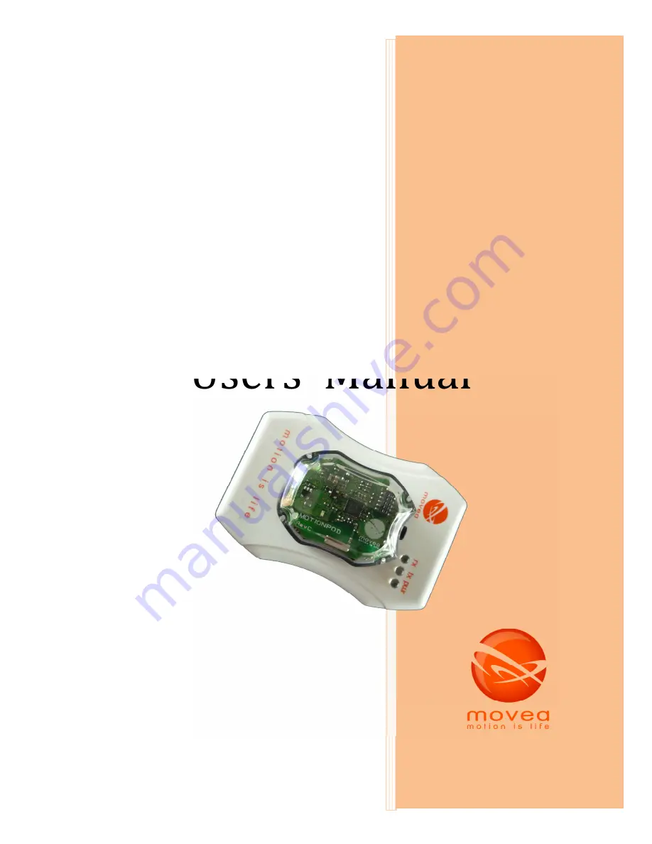
MotionPod™
System
Users’ Manual
Страница 1: ...Copyright 2011 Movea All rights reserved EN 2011 Version 7 MotionPod System Users Manual ...
Страница 2: ...charging your MOTIONPOD 9 2 How to switch the MOTIONPOD on off 10 3 How to wear the MOTIONPOD 10 VIII Precautions 11 1 Using environments 11 2 Characteristics and environmental conditions 12 IX Calibration 13 X Cleaning 14 1 Cleaning the MOTIONCONTROLLER 14 2 Cleaning the MOTIONPOD 14 XI Signs and labels 15 1 MOTIONPOD 15 2 MOTIONCONTROLLER 16 3 CHARGER 16 XII Maintenance 17 XIII What to do in cas...
Страница 3: ...eiver of the MPOD device Designates data receiving and or recharging case which connects on the computer via USB port See figure 2 below CHARGER Designates the recharging case which connects to the computer via USB port and is used only for charging the MPOD It does not have data receiving capabilities Please note that CTRLER CHARGER initials are mentioned on the labels at the back of the devices ...
Страница 4: ... Transparent top cover Blackbottom cover FIGURE 1 MOTIONPOD MPOD charging cavity Spring contacts for electrical link with the MPOD Light indicators USB port rx tx pwr Green power light indicates that the Motion Controller is receiving power Blue RX TX lights RX signal reception TX signal transmission FIGURE 2 MOTIONCONTROLLER ...
Страница 5: ... ion battery of the MPOD Do not use non rechargeable battery or any other battery that could damage the product and presents health risks or cause accidents DO NOT EXPOSE TO FIRE Risk of explosion DO NOT OPEN CAUTION For your own safety do not open the charging case risk of electric shock CAUTION the USB cable serves as a disconnection device Waste management process of electric and electronic pro...
Страница 6: ...ation of a patient s part of body Any other use must be avoided This product designed and manufactured by Movea is well adapted for biomechanical applications rehabilitation and joint assessment in physical therapy For this reason it must be used in a controlled environment at a practice office and by qualified personnel The user of MPOD must have red and understood this notice The MPOD System is ...
Страница 7: ...k bottom cover of the MPOD This part allows fixing the MPOD on any kind of supporting facet designed to accommodate it It can be the charging box see below or the mechanical interface for bracelet or strap Figure 1 summarizes the first visual elements on the MPOD FIGURE 4 MPOD MECHNICAL INTERFACE FOR BRACELET OR STRAP 2 MOTIONCONTROLLER The CTRLER is a white case with a surface identical to that o...
Страница 8: ...ARGER FIGURE 6 MPOD CHARGER The CHARGER and the CTRLER have the same casing Since the CTRLER has the same functionality the CHARGER is therefore optional It s only needed when several MPODs need to be charged regularly On the upper facet you can see an imprinted logo of Movea and light indicator inscriptions see below for their significance At the back of the Motion controller a sticker imprinted ...
Страница 9: ...e MPOD by its Black bottom cover directly in the cavity The button of the MPOD must be pointing to the Logo The MPOD must completely fit in the cavity A clockwise rotation of approximately 30 mechanically locks the MPOD in the cavity and therefore electrically connects it to the CTRLER for recharge A click sound indicates that the system is suitably locked and started charging if charging is neede...
Страница 10: ...ge the MPOD and will void your manufacturer s warranty The MPOD should not be opened Battery replacement should only be carried out by your supplier 2 HOW TO SWITCH THE MOTIONPOD ON OFF The MOTIONCONTROLLER must be connected to the PC The MPOD must formerly be recharged Take the MPOD off the CTRLER Slightly push the button on the MPOD to switch it on At this stage the green light indicator blinks ...
Страница 11: ...health professional Indications given by the MPOD are provided as an indication The MPOD encloses sensors that to measure orientation parameters in space These measurements should not be used for diagnosis They are only informative and meant to support the physical therapists decision They are not certified so the information they give must be subject to discussion Like any other electronic device...
Страница 12: ...d for static and quasi static positions When using gyroscopes body motion must be limited to sensors limit The measured orientation parameter is valid in a uniform or quasi uniform magnetic field between 6 gauss and 6 gauss1 Maximum Shock resistance 4600 g for a time of 0 5 ms MPOD should not be thrown away violently It is however resistant to shocks in normal conditions of use Magnetic field surv...
Страница 13: ...over a long period of time or after a magnetic shock the sensors are likely to drift It is then necessary to calibrate In static mode irregularities on accelerometer measures can be due to a very fast movement The software will probably request re recording with a slower gesture If magnetometers are responsible for the anomaly it s more likely because there are magnetic disturbances in the environ...
Страница 14: ... cloth 2 CLEANING THE MOTIONPOD MPOD and the mechanical interface are made of natural polycarbonate for the transparent cover and of polycarbonate the Black bottom cover and mechanical interface The button on MPOD is in NBR Use products listed below or other products compatible with these materials Cleaning products must be compatible with Polycarbonate Do not immerse the MPOD in these products Us...
Страница 15: ...E certified bandage example Urgoderm band see figure 7 FIGURE 9 BIOCOMPATIBLE BANDAGES TO PUT BETWEEN THE SKIN AND MPOD XI SIGNS AND LABELS 1 MOTIONPOD The MPOD is the part of the system in contact with the subject Label of the MPOD on the bottom cover We can see The CE mark Radio frequency presence indicator Barcode with serial numbers Refer to the user manual symbol 15 mm of diameter ...
Страница 16: ...16 2 MOTIONCONTROLLER The label of the CTRLER figures at the bottom of the case Dimension 30 x 33 mm 3 CHARGER Labeling of the CHARGER figure below Dimension 30 x 33 mm ...
Страница 17: ... The CTRLER doesn t work properly the green light indicator doesn t go n when plugged on PC Make sure that the PC is on and working Change the USB cable If problem persists contact your local provider The MPOD green light indicator doesn t go on when pushing the button Make sure that the battery is not empty for that place it on the CTRLER The CTRLER must be plugged on a running PC The orange ligh...
Страница 18: ...uarantee that interference will not occur in a particular installation FCC Statement This device complies with part 15 of the FCC Rules Operation is subject to the following two conditions 1 This device may not cause harmful interference and 2 this device must accept any interference received including interference that may cause undesired operation Changes or modifications not expressly approved ...