


H A R D W A R E I N S T A L L A T I O N
34
Quarter-inch outputs can be trimmed in the DAC
itself. Range is 24 dB. The Main Outs and Phones
provide full trim range from 0 dB to -
∞
(-127).
Trim controls are most easily accessed in the web
app. See “Device tab” on page 12. Trim settings can
also be accessed in the LCD menu.
Optical I/O
The UltraLite-mk4 provides ADAT optical
(“lightpipe”) connectors (one input and one
output). Together, they provide 8 channels of
ADAT optical digital I/O at 44.1 or 48 kHz, or 4
channels of SMUX optical at 2x sample rates (88.2
or 96 kHz). SMUX operation supports two modes
(item #21 on page 13):
■
Standard
— for 2x optical connection to
3rd-party SMUX-compatible hardware products.
■
Type II (Legacy)
— for 2x optical connection to
legacy MOTU products that are equipped with
optical ports and support 2x operation.
The optical ports are disabled when the interface is
operating at a 176.4 or 192 kHz.
TOSLink (optical S/PDIF)
Alternately, the optical ports can be configured for
stereo TOSLink (optical S/PDIF) in the web app
(item #21 on page 13). The optical IN and OUT
banks can be configured independently.
Choosing a clock source for optical connections
When connecting an
optical
device, make sure that
its digital audio clock is phase-locked (in sync
with) the UltraLite-mk4. There are two ways to do
this:
A. Resolve the optical device to the UltraLite-mk4
B. Resolve the UltraLite-mk4 to the optical device
For A, choose
Internal
(or anything other than
Optical
) as the clock source in the Device tab (item
#13 on page 12). Then configure the other device
to resolve to its optical input.
For B, choose
Optical
as the clock source (item #13
on page 12), and configure the other device to
resolve to its own internal clock.
S/PDIF
If you make a S/PDIF digital audio connection to
another device, the UltraLite-mk4 must be
digitally synced with the other device for a clean,
click-free digital audio stream between them.
DAT decks and other devices with S/PDIF digital
I/O will sync to the UltraLite-mk4 input via the
S/PDIF connection itself. Just connect it to the
UltraLite-mk4 S/PDIF output connector. When
the device records a digital audio signal (from the
UltraLite-mk4), it will simply synchronize to the
clock provided by the signal.
When you transfer audio from the S/PDIF device
into the UltraLite-mk4, you’ll have to resolve the
UltraLite-mk4 to its S/PDIF input.
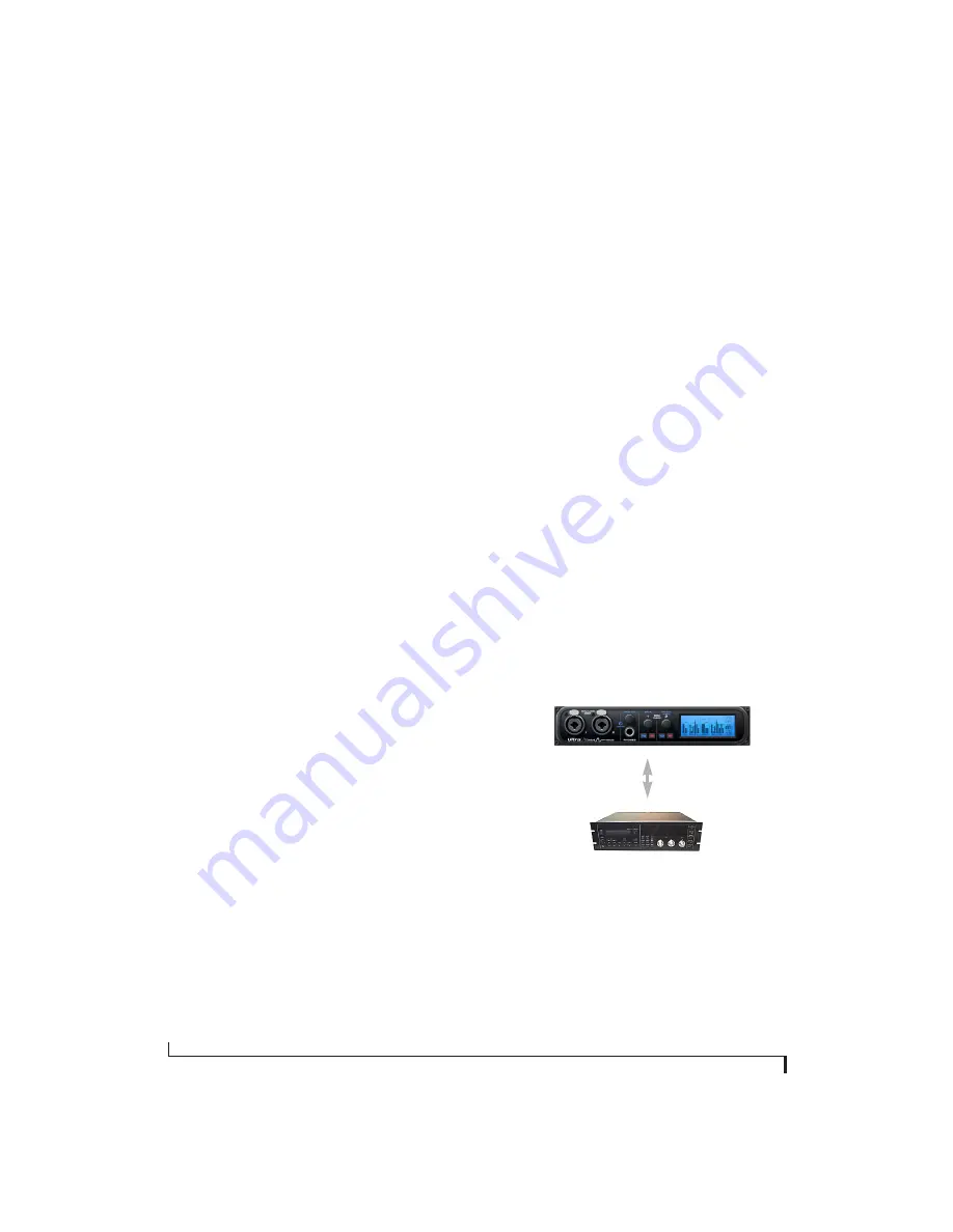
Figure 4-2: The setup for synchronizing a S/PDIF device with the
UltraLite-mk4. Sync is achieved via the digital I/O connection itself. In
this case, you have to choose S/PDIF as the UltraLite-mk4’s clock
source when recording from the other device.
S/PDIF
S/PDIF device
UltraLite-mk4
UltraLite-mk4
Clock Source setting =
Internal
(when transferring from the
UltraLite-mk4 to the other device)
UltraLite-mk4
Clock Source setting =
S/PDIF
(when transferring from the
other device to the UltraLite-mk4)
S/PDIF
Содержание UltraLite-mk4
Страница 5: ...Part1 GettingStarted...
Страница 6: ......
Страница 8: ...8...
Страница 22: ...M O T U P R O A U D I O C O N T R O L W E B A P P 22...
Страница 26: ...P A C K I N G L I S T A N D S Y S T E M R E Q U I R E M E N T S 26...
Страница 37: ...Part2 Usingthe UltraLite mk4...
Страница 38: ......
Страница 42: ...P R E S E T S 42...
Страница 60: ...M I X E R E F F E C T S 60...
Страница 77: ...Part3 Appendices...
Страница 78: ......
Страница 83: ...APPENDIX 83 C Mixer Schematics MONO INPUT CHANNEL...
Страница 84: ...A P P E N D I X C M I X E R S C H E M A T I C S 84 STEREO INPUT CHANNEL...
Страница 85: ...A P P E N D I X C M I X E R S C H E M A T I C S 85 GROUP BUS...
Страница 86: ...A P P E N D I X C M I X E R S C H E M A T I C S 86 MONITOR BUS...
Страница 90: ...A P P E N D I X E A U T O O N M O D E 90...
Страница 94: ...I N D E X 94...


