


Functional Description
http://www.motorola.com/computer/literature
4-7
4
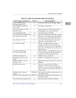
the second 1MB space (which is reserved for future expansion). The
EPROMs may either coexist with this 2MB of Flash, or can be used to
program all 4MB of Flash (after which configuration switch S4 could be
reset to make only Flash available).
After a system reset, the EPROMs are mapped to the default addresses
$00000 through $FFFFF. They may be mapped to $FF800000 through
$FF8FFFFF if necessary. The selection between mapping EPROM/Flash
mixed mode or all-Flash mode is done by the combination of board
configuration switch S4 and VMEchip2 control bit GPIO2.
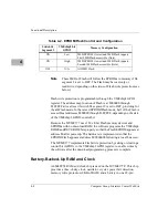
shows how the “EPROM/Flash” switch and GPIO bit 2 control the
EPROM/Flash configuration.
The EPROMs are mapped to local bus address 0 following a local bus
reset. This allows the MC68060 to access the stack pointer and execution
address following a reset. The EPROMs are controlled by the VMEchip2
ASIC. The map decoder, the access time, and the time they appear at
address 0 are all programmable items. For more detail, refer to the
VMEchip2 description in the Programmer’s Reference Guide.
Flash Memory
The MVME177 includes four 28F008SA Flash memory devices. The
Flash devices provide 4MB of ROM at address $FF800000-$FFBFFFFF.
The Flash memory is organized as one 32-bit bank for 32-bit code
execution from the processor. The Flash can be used for storage of the
onboard debugger firmware (177Bug) which could be downloaded from
I/O resources such as Ethernet, SCSI or serial devices, or the VMEbus.
When Flash is used with EPROM, either the top or bottom 2MB of Flash
is available in the second 2MB of memory space after the EPROM. Refer
to
below.
Because only 1M x 8-bit Flash chips are used, no jumper or switch
configuration is necessary to select the Flash chip size.
The memory map for the Flash devices is under the control of the
VMEchip2 ASIC. The 32-bit wide Flash can support 8-, 16-, and 32-bit
read accesses.
Содержание MVME177P
Страница 1: ...MVME177P Single Board Computer Installation and Use V177PA IH1 Edition of October 2000 ...
Страница 10: ...x ...
Страница 12: ...xii ...
Страница 14: ...xiv ...
Страница 34: ...1 16 Computer Group Literature Center Web Site Hardware Preparation and Installation 1 ...
Страница 48: ...2 14 Computer Group Literature Center Web Site Startup and Operation 2 ...
Страница 92: ...C 2 Computer Group Literature Center Web Site Network Controller Data C ...
Страница 98: ...D 6 Computer Group Literature Center Web Site Disk Tape Controller Data D ...
Страница 108: ...Index IN 6 Computer Group Literature Center Web Site I N D E X ...


