


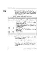


1-14
Computer Group Literature Center Web Site
Hardware Preparation and Installation
1
Whether the MVME177P operates as a VMEbus master or VMEbus slave,
it is configured for 32 bits of address and 32 bits of data (A32/D32).
However, it handles A16 or A24 devices in the address ranges indicated in
the VMEchip2 chapter of the Programmer’s Reference Guide. D8 and/or
D16 devices in the system must be handled by the MC68060 software. For
specifics, refer to the memory maps in the Programmer’s Reference Guide.
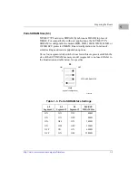
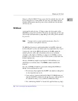
The MVME177P contains shared onboard DRAM whose base address is
software-selectable. Both the onboard processor and offboard VMEbus
devices see this local DRAM at base physical address $00000000, as
programmed by the MVME177Bug firmware. This may be changed via
software to any other base address. Refer to the MVME1X7P Single Board
Computers Programmer’s Reference Guide for more information.
If the MVME177P tries to access offboard resources in a nonexistent
location and is not system controller, and if the system does not have a
global bus timeout, the MVME177P waits forever for the VMEbus cycle
to complete. This will cause the system to lock up. There is only one
situation in which the system might lack this global bus timeout: when the
MVME177P is not the system controller and there is no global bus timeout
elsewhere in the system.
Multiple MVME177Ps may be installed in a single VME chassis. In
general, hardware multiprocessor features are supported.
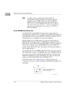
Other MPUs on the VMEbus can interrupt, disable, communicate with,
and determine the operational status of the processor(s). One register of the
GCSR (global control/status register) set in the VMEchip2 ASIC includes
four bits that function as location monitors to allow one MVME177P
processor to broadcast a signal to any other MVME177P processors. All
eight registers of the GCSR set are accessible from any local processor as
well as from the VMEbus.
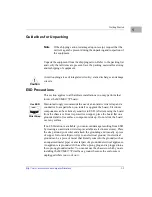
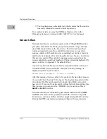
The MVME177P pr12Vdc power to the Ethernet LAN transceiver
interface through a 1A solid-state fuse (R24)
located on the MVME177P
module. The
+12V
LED illuminates when +12Vdc is available. If the
Ethernet transceiver fails to operate, check the status of R24.
The MVME177P provides SCSI terminator power through a 1A fuse (F1)
located on the LCP2 adapter board. The fuse is socketed. If the fuse is
blown, the SCSI device(s) may function erratically or not at all.
Содержание MVME177P
Страница 1: ...MVME177P Single Board Computer Installation and Use V177PA IH1 Edition of October 2000 ...
Страница 10: ...x ...
Страница 12: ...xii ...
Страница 14: ...xiv ...
Страница 34: ...1 16 Computer Group Literature Center Web Site Hardware Preparation and Installation 1 ...
Страница 48: ...2 14 Computer Group Literature Center Web Site Startup and Operation 2 ...
Страница 92: ...C 2 Computer Group Literature Center Web Site Network Controller Data C ...
Страница 98: ...D 6 Computer Group Literature Center Web Site Disk Tape Controller Data D ...
Страница 108: ...Index IN 6 Computer Group Literature Center Web Site I N D E X ...


