
Chapter 2. Signal Descriptions and Clocking
2-29
Detailed Signal Descriptions
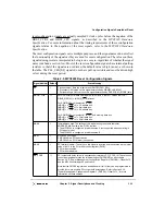
about the power management signals. Following are the state meaning and timing
comments for the QACK output signal.
State Meaning
Asserted—Indicates that the processor core and peripheral logic are
in either nap or sleep mode.
Negated—Indicates that the processor core and peripheral logic are
not in nap or sleep mode.
2.2.5.9 Watchpoint Trigger Signals
There is one watchpoint trigger input and one watchpoint trigger output signal that together
provide a programmable output signal and control of the watchpoint facility. See
Chapter 16, “Programmable I/O and Watchpoint,” for more information about the
watchpoint facility.
2.2.5.9.1
Watchpoint Trigger In (TRIG_IN)—Input
The watchpoint trigger in (TRIG_IN) signal is an input on the MPC8240. Following are the
state meaning and timing comments for the TRIG_IN signal. Note that TRIG_IN is an
active-high (rising-edge triggered) signal.
State Meaning
Asserted—May cause the MPC8240 to exit the HOLD state, or
causes the value of the WP_RUN bit in the WP_CONTROL register
to toggle (turning the watchpoint facility on or off). See Chapter 16,
“Programmable I/O and Watchpoint,” for more information.
Negated—No action taken.
Timing Comments
Assertion/Negation—The MPC8240 interprets TRIG_IN as asserted
on detection of the rising edge of TRIG_IN. Only required to be
asserted for a single clock cycle.
2.2.5.9.2 Watchpoint Trigger Out (TRIG_OUT)—Output
The watchpoint trigger out (TRIG_OUT) signal is an output on the MPC8240. Following
are the state meaning and timing comments for the TRIG_OUT signal. Note that the active
sense of TRIG_OUT is controlled by the setting of WP_CONTROL[WP_TRIG].
State Meaning
Asserted—Indicates that a final watchpoint match has occurred, as
defined in the WP_MODE field of the WP_CONTROL register.
Negated—No final watchpoint match condition.
Timing Comments
Assertion/Negation—Asserted until TRIG_IN is asserted, unless the
WP_TRIG_HOLD parameter in the WP_CONTROL register is
cleared. Then TRIG_OUT is asserted for a single clock cycle.
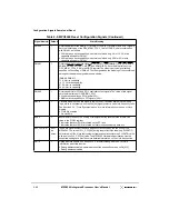
2.2.5.10 Debug Signals
The following sections describe the debug signals used by the MPC8240 in various debug
modes. See Chapter 15, “Debug Features,” for more details and timing information on the
debug signals.
Содержание MPC8240
Страница 1: ...MPC8240UM D Rev 1 1 2001 MPC8240 Integrated Processor User s Manual ...
Страница 38: ...xviii MPC8240 Integrated Processor User s Manual TABLES Table Number Title Page Number ...
Страница 48: ...xlviii MPC8240 Integrated Processor User s Manual Acronyms and Abbreviations ...
Страница 312: ...6 94 MPC8240 Integrated Processor User s Manual ROM Flash Interface Operation ...
Страница 348: ...7 36 MPC8240 Integrated Processor User s Manual PCI Host and Agent Modes ...
Страница 372: ...8 24 MPC8240 Integrated Processor User s Manual DMA Register Descriptions ...
Страница 394: ...9 22 MPC8240 Integrated Processor User s Manual I2O Interface ...
Страница 412: ...10 18 MPC8240 Integrated Processor User s Manual Programming Guidelines ...
Страница 454: ...12 14 MPC8240 Integrated Processor User s Manual Internal Arbitration ...
Страница 466: ...13 12 MPC8240 Integrated Processor User s Manual Exception Latencies ...
Страница 516: ...16 14 Watchpoint Trigger Applications ...
Страница 538: ...B 16 MPC8240 Integrated Processor User s Manual Setting the Endian Mode of Operation ...
Страница 546: ...C 8 MPC8240 Integrated Processor User s Manual ...
Страница 640: ...INDEX Index 16 MPC8240 Integrated Processor User s Manual ...


