


Chapter 13. Error Handling
13-3
Exceptions and Error Signals
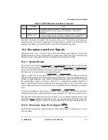
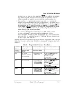
Note that for priority 1 through 5, the exception is the same. The machine check exception
and the priority are related to additional error information provided by the MPC8240 (for
example, the address provided in the Processor/PCI error address register).
13.2 Exceptions and Error Signals
Although Section 2.2.5, “System Control and Power Management Signals,” contains the
signal definitions for the exception and error signals, this section describes the interactions
between system components when an exception or error signal is asserted.
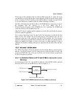
13.2.1 System Reset
The system reset exception is an asynchronous, nonmaskable interrupt that occurs when the
hard reset input signals are (HRST_CPU and HRST_CTRL are both) asserted (required at
power-on). The MPC8240 has two hard reset input signals, HRST_CPU and HRST_CRTL,
and they must be asserted and negated simultaneously.
When a system reset is recognized (HRST_CPU and HRST_CTRL are both asserted), the
MPC8240 aborts all current internal and external transactions, releases all bidirectional I/O
signals to a high-impedance state, ignores the input signals (except for PCI_SYNC_IN and
the configuration signals described in Section 2.4, “Configuration Signals Sampled at
Reset”), and drives most of the output signals to an inactive state. Table 2-2 shows the states
of the output-only signals during system reset. The MPC8240 then initializes its internal
logic.
For proper initialization, the assertion of HRST_CPU and HRST_CTRL must satisfy the
minimum active pulse width requirements given in the MPC8240 Hardware Specification.
Note that the latches dedicated to JTAG functions are not initialized during system reset.
The IEEE 1149.1 standard prohibits the device reset from resetting the JTAG logic. The
JTAG reset (TRST) signal is required to reset the dedicated JTAG logic during power-on.
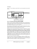
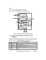
13.2.2 Processor Core Error Signal (mcp)
The MPC8240 provides an internal machine check signal (mcp) to the processor core for
error reporting.
4
Machine check
PCI address parity error (SERR) or PCI data parity error (PERR) when the
MPC8240 is acting as the PCI master, PCI master-abort, or received PCI
target-abort
5
Machine check
NMI (nonmaskable interrupt), inbound doorbell register machine check (IDBR[MC]),
or inbound message register overflow flags (IMISR[OFO] and IMISR[IPO])
Table 13-1. MPC8240 Error Priorities (Continued)
Priority
Exception
Cause
Содержание MPC8240
Страница 1: ...MPC8240UM D Rev 1 1 2001 MPC8240 Integrated Processor User s Manual ...
Страница 38: ...xviii MPC8240 Integrated Processor User s Manual TABLES Table Number Title Page Number ...
Страница 48: ...xlviii MPC8240 Integrated Processor User s Manual Acronyms and Abbreviations ...
Страница 312: ...6 94 MPC8240 Integrated Processor User s Manual ROM Flash Interface Operation ...
Страница 348: ...7 36 MPC8240 Integrated Processor User s Manual PCI Host and Agent Modes ...
Страница 372: ...8 24 MPC8240 Integrated Processor User s Manual DMA Register Descriptions ...
Страница 394: ...9 22 MPC8240 Integrated Processor User s Manual I2O Interface ...
Страница 412: ...10 18 MPC8240 Integrated Processor User s Manual Programming Guidelines ...
Страница 454: ...12 14 MPC8240 Integrated Processor User s Manual Internal Arbitration ...
Страница 466: ...13 12 MPC8240 Integrated Processor User s Manual Exception Latencies ...
Страница 516: ...16 14 Watchpoint Trigger Applications ...
Страница 538: ...B 16 MPC8240 Integrated Processor User s Manual Setting the Endian Mode of Operation ...
Страница 546: ...C 8 MPC8240 Integrated Processor User s Manual ...
Страница 640: ...INDEX Index 16 MPC8240 Integrated Processor User s Manual ...


