


10-14
MPC8240 Integrated Processor User’s Manual
Programming Guidelines
10.4.1 Initialization Sequence
A hard reset initializes all the I
2
C registers to their default states. The following
initialization sequence must be used before the I
2
C unit:
1. If the processor’s memory management unit (MMU) is enabled, all I
2
C registers
must be located in a cache-inhibited area.
2. Program the embedded utilities memory block; see Section 3.4, “Embedded
Utilities Memory Block (EUMB).”
3. Update I2CFDR[FDR] and select the required division ratio to obtain the SCL
frequency from the local memory clock (SDRAM_CLK).
4. Update the I2CADR to define the slave address for this device.
5. Modify I2CCR to select master/slave mode, transmit/receive mode, and
interrupt-enable or disable.
6. Set the I2CCR[MEN] to enable the I
2
C interface.
10.4.2 Generation of START
After initialization, the following sequence can be used to generate START:
1. If the MPC8240 is connected to a multimaster I
2
C system, test the state of
I2CSR[MBB] to check whether the serial bus is free (I2CSR[MBB] = 0) before
switching to master mode.
2. Select master mode (set I2CCR[MSTA]) to transmit serial data.
3. Write the slave address being called into the data register (I2CDR). The data written
to I2CDR[7–1] comprises the slave calling address. I2CCR[MTX] indicates the
direction of transfer (transmit/receive) required from the slave.
4. Set I2CCR[MTX] for the address cycle.
The above scenario assumes the I
2
C interrupt bit (I2CSR[MIF]) is cleared. If
I2CSR[MIF] = 1 at any time, the I
2
C interrupt handler should immediately handle the
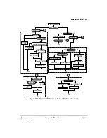
interrupt. See Section 10.4.8, “Interrupt Service Routine Flowchart.”
10.4.3 Post-Transfer Software Response
Transmission or reception of a byte automatically sets the data transferring bit
(I2CSR[MCF]), which indicates that one byte has been transferred. The I
2
C interrupt bit
(I2CSR[MIF]) is also set; an interrupt is generated to the processor if the interrupt function
is enabled during the initialization sequence (I2CCR[MIEN] = 1). In the interrupt handler,
software must do the following:
•
Clear I2CSR[MIF]
•
Read the contents of the I
2
C data register (I2CDR) in receive mode or write to
I2CDR in transmit mode. Note that this causes I2CSR[MCF] to be cleared. See
Section 10.4.8, “Interrupt Service Routine Flowchart.”
Содержание MPC8240
Страница 1: ...MPC8240UM D Rev 1 1 2001 MPC8240 Integrated Processor User s Manual ...
Страница 38: ...xviii MPC8240 Integrated Processor User s Manual TABLES Table Number Title Page Number ...
Страница 48: ...xlviii MPC8240 Integrated Processor User s Manual Acronyms and Abbreviations ...
Страница 312: ...6 94 MPC8240 Integrated Processor User s Manual ROM Flash Interface Operation ...
Страница 348: ...7 36 MPC8240 Integrated Processor User s Manual PCI Host and Agent Modes ...
Страница 372: ...8 24 MPC8240 Integrated Processor User s Manual DMA Register Descriptions ...
Страница 394: ...9 22 MPC8240 Integrated Processor User s Manual I2O Interface ...
Страница 412: ...10 18 MPC8240 Integrated Processor User s Manual Programming Guidelines ...
Страница 454: ...12 14 MPC8240 Integrated Processor User s Manual Internal Arbitration ...
Страница 466: ...13 12 MPC8240 Integrated Processor User s Manual Exception Latencies ...
Страница 516: ...16 14 Watchpoint Trigger Applications ...
Страница 538: ...B 16 MPC8240 Integrated Processor User s Manual Setting the Endian Mode of Operation ...
Страница 546: ...C 8 MPC8240 Integrated Processor User s Manual ...
Страница 640: ...INDEX Index 16 MPC8240 Integrated Processor User s Manual ...


