Chapter 7. PCI Bus Interface
7-3
PCI Interface Overview
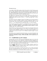
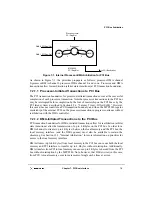
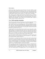
7.1.2 The MPC8240 as a PCI Target
As a target, upon detection of a PCI address phase the MPC8240 decodes the address and
bus command to determine if the transaction is for local memory. If the transaction is
destined for local memory, the target interface latches the address, decodes the PCI bus
command, and forwards them to an internal control unit. On writes to local memory, data
is forwarded along with the byte enables to the internal control unit. On reads, four bytes
of data are provided to the PCI bus and the byte enables determine which byte lanes contain
meaningful data.
The target interface of the MPC8240 can issue target-abort, target-retry, and
target-disconnect cycles. The target interface supports fast back-to-back transactions and
exclusive accesses using the PCI lock protocol. The target interface uses the fastest device
selection timing.
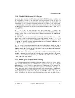
The MPC8240 supports data streaming to and from local memory. This means that the
MPC8240 can accept or provide data to or from local memory as long as the internal
PCI-to-system-memory-write-buffers (PCMWBs) or PCI-to-system-memory-read buffers
(PCMRBs) are not filled. For more information about the internal buffers of the MPC8240,
see Chapter 12, “Central Control Unit.”
There are two 32-byte PCMWBs and while one is filled from the PCI master, the other is
flushed to local memory. Some memory operations (such as refresh) can stall the flushing
of the PCMWBs. In that case, the MPC8240 issues a target disconnect when there is no
more space remaining in the PCMWBs.
Burst reads from local memory are accepted with wait states inserted depending upon the
timing of local memory devices. The MPC8240 has two 32-byte PCMRBs and can provide
continuous data to a PCI master by flushing one PCMRB to the PCI master while the other
is being filled from local memory.
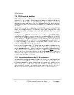
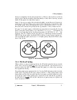
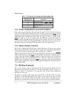
7.1.3 PCI Signal Output Hold Timing
In order to meet minimum output hold specifications relative to PCI_SYNC_IN for both 33
MHz and 66 MHz PCI systems, the MPC8240 has a programmable output hold delay for
PCI signals. The initial value of the output hold delay is determined by the values on the
MCP and CKE power-on reset configuration signals (see Section 2.4, “Configuration
Signals Sampled at Reset”). Further output hold delay values are available by programming
the PCI_HOLD_DEL value of the PMCR2 configuration register. Refer to Section 4.3.2,
“Power Management Configuration Register 2 (PMCR2)—Offset 0x72,” and the
MPC8240 Hardware Specification
for more information on these values and signal timing.
Содержание MPC8240
Страница 1: ...MPC8240UM D Rev 1 1 2001 MPC8240 Integrated Processor User s Manual ...
Страница 38: ...xviii MPC8240 Integrated Processor User s Manual TABLES Table Number Title Page Number ...
Страница 48: ...xlviii MPC8240 Integrated Processor User s Manual Acronyms and Abbreviations ...
Страница 312: ...6 94 MPC8240 Integrated Processor User s Manual ROM Flash Interface Operation ...
Страница 348: ...7 36 MPC8240 Integrated Processor User s Manual PCI Host and Agent Modes ...
Страница 372: ...8 24 MPC8240 Integrated Processor User s Manual DMA Register Descriptions ...
Страница 394: ...9 22 MPC8240 Integrated Processor User s Manual I2O Interface ...
Страница 412: ...10 18 MPC8240 Integrated Processor User s Manual Programming Guidelines ...
Страница 454: ...12 14 MPC8240 Integrated Processor User s Manual Internal Arbitration ...
Страница 466: ...13 12 MPC8240 Integrated Processor User s Manual Exception Latencies ...
Страница 516: ...16 14 Watchpoint Trigger Applications ...
Страница 538: ...B 16 MPC8240 Integrated Processor User s Manual Setting the Endian Mode of Operation ...
Страница 546: ...C 8 MPC8240 Integrated Processor User s Manual ...
Страница 640: ...INDEX Index 16 MPC8240 Integrated Processor User s Manual ...

